

Dyaco SE578B-YE014, SE598B-YE016 Service Manual
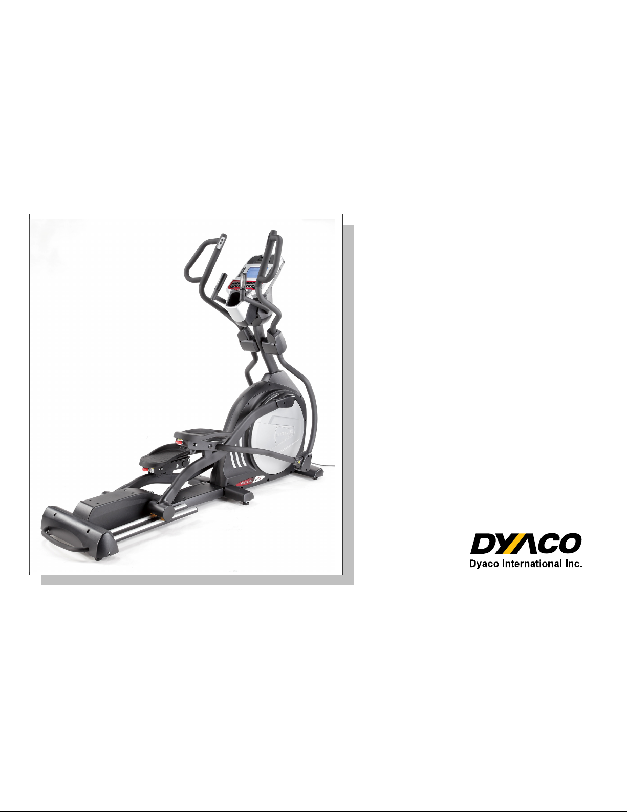
SE578B-YE014
Elliptical
Service Manual

SSeerrvviiccee MMaannuuaal
l
-1-
-----------------------------------------Table of Content-----------------------------------------------
1. SE578B Elliptical Outlines
2. Electronic Parts
2.1 Upper Controllers
2.2 Lower Controller and Driver
3. Electrical Configurations
4. Elliptical Operation
5. Elliptical Unit Block Diagrams
6. Elliptical Basic Connections and Wiring
6.1 Display Board Wire Connections
6.2 Display Board PCB Component Locations
6.3 The Console Interface Board Wire Connections
6.4 Amplifier Board Wire Connections
6.5 Driver Board Wire Connections
6.6 Driver Board PCB Component Locations
6.7 Driver Board LED Indicator Locations
6.8 Controller Indicator LED Debugging
6.9 Driver Board Function
6.10 Tension Motor Connector Definition Function
7. Product Safety Instructions
7.1 Important Safety Instructions
7.2 Important Electrical Instructions
7.3 Important Grounding Instructions
8. Elliptical Error Messages and Troubleshooting for electronic Issues
8.1 Error Message: E1
8.2 Error Message: E2
8.3 Error Message: E3
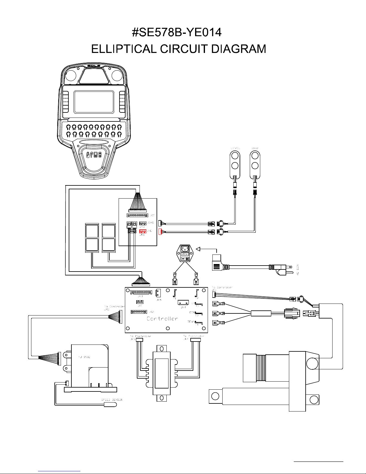
8.4 Circuit Diagram
8.5 Calibration Procedure
8.6 Fuse Replacement
8.7 Troubleshooting Procedure Matrix for Electronic Issues

SSeerrvviiccee MMaannuuaal
l
-2-
9. Troubleshooting
9.1 Console Problem
9.2 Side Case & Round Disk Problem
9.3 Flywheel Problem
9.4 Poly-V Belt Problem
9.5 Swing Arm Problem
9.6 Connecting Arm Problem
9.7 Controller & Incline Motor Problem
9.8 Tension Motor Problem
10. Q & A
10.1 Noise
10.2 Slip Problem
10.3 Resistance & Incline Problem
10.4 Smooth Problem
11. Disassembling and Assembling of Parts
11.1 Console Replacement
11.2 Swing Arm Replacement
11.3 Connecting Arm Replacement
11.4 Pedal Arm Replacement
11.5 Console Mast Replacement
11.6 Side Case Replacement
11.7 Cross Bar Replacement
11.8 Idler Wheel Replacement
11.9 Flywheel & Poly-V Belt Replacement
11.10 Rear Frame Replacement
11.11 滑動管焊件組及揚升馬達更換
滑動管焊件組及揚升馬達更換滑動管焊件組及揚升馬達更換
滑動管焊件組及揚升馬達更換 Rail & Incline Motor Replacement
SSeerrvviiccee MMaannuuaal
l
-3-
Circuit Diagram

SSeerrvviiccee MMaannuuaal
l
-4-
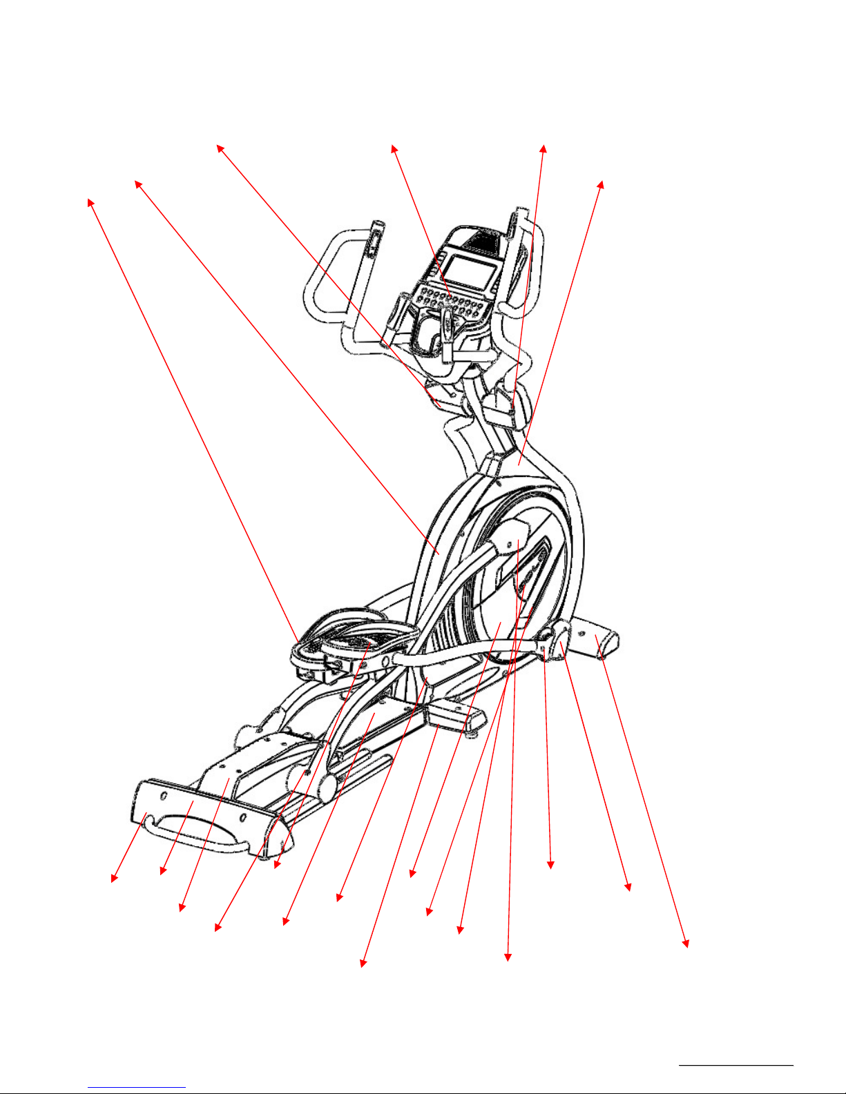
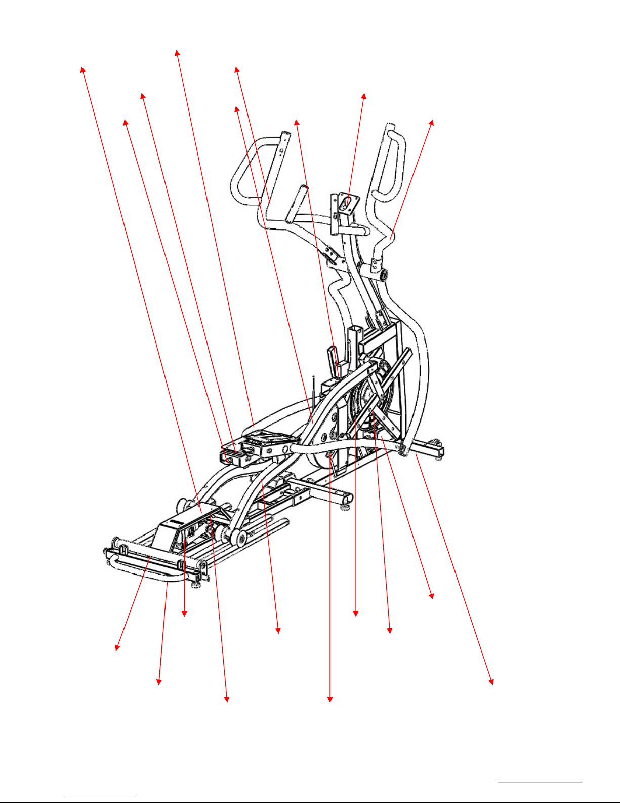
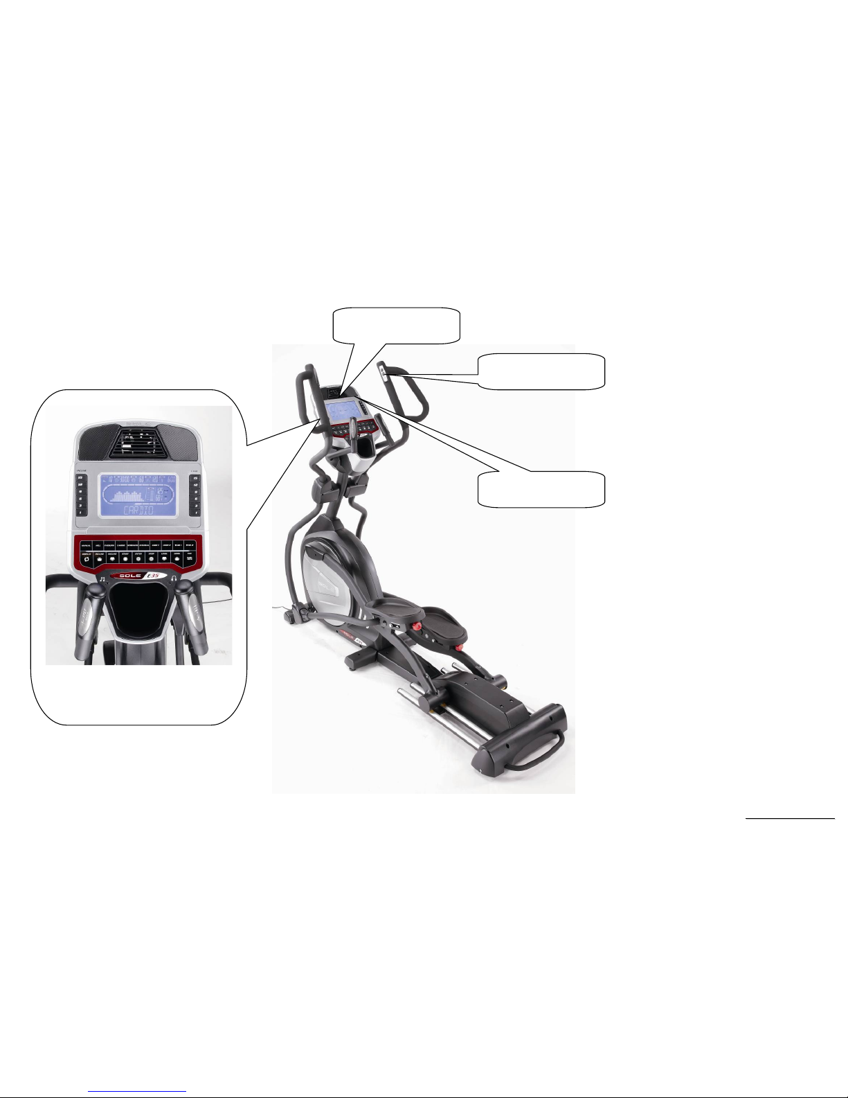
1. Elliptical Outlines
SSeerrvviiccee MMaannuuaal
l
-5-
(1) Plastic parts
Front handlebar
Cover (L)
Front handlebar cover(R) Console
Left side case
Pedal(L)
Console mast cover
Rear cover(1)
Front cover
Connecting arm cover(B)
Middle cover
Slide wheel cover
Bottom cover
Right side case
Bottom-middle case
Round disk cover
Pedal arm cover(R)
Connecting arm cover(A)
Pedal(R)
Round disk
Rear cover(
2)
SSeerrvviiccee MMaannuuaal
l
-6-
(2) Steel parts
Pedal arm (L)
Adjustable pedal
Adjusting knob
Connecting arm (L)
Flywheel
Tension motor
Console mast
Swing arm (L)
Swing arm (R)
Rail assembly
Incline motor
Pedal arm (R)
Drive Pulley
Cross Bar
Controller
Main
frame
Connecting arm (R) Middle frame
Rear frame

SSeerrvviiccee MMaannuuaal
l
-7-
2. Electronic Parts
SSeerrvviiccee MMaannuuaal
l
-8-
2.1 Upper Controllers
DISPLAY
Cooling FAN
THUMB SWITCH
Speaker
SSeerrvviiccee MMaannuuaal
l
-9-
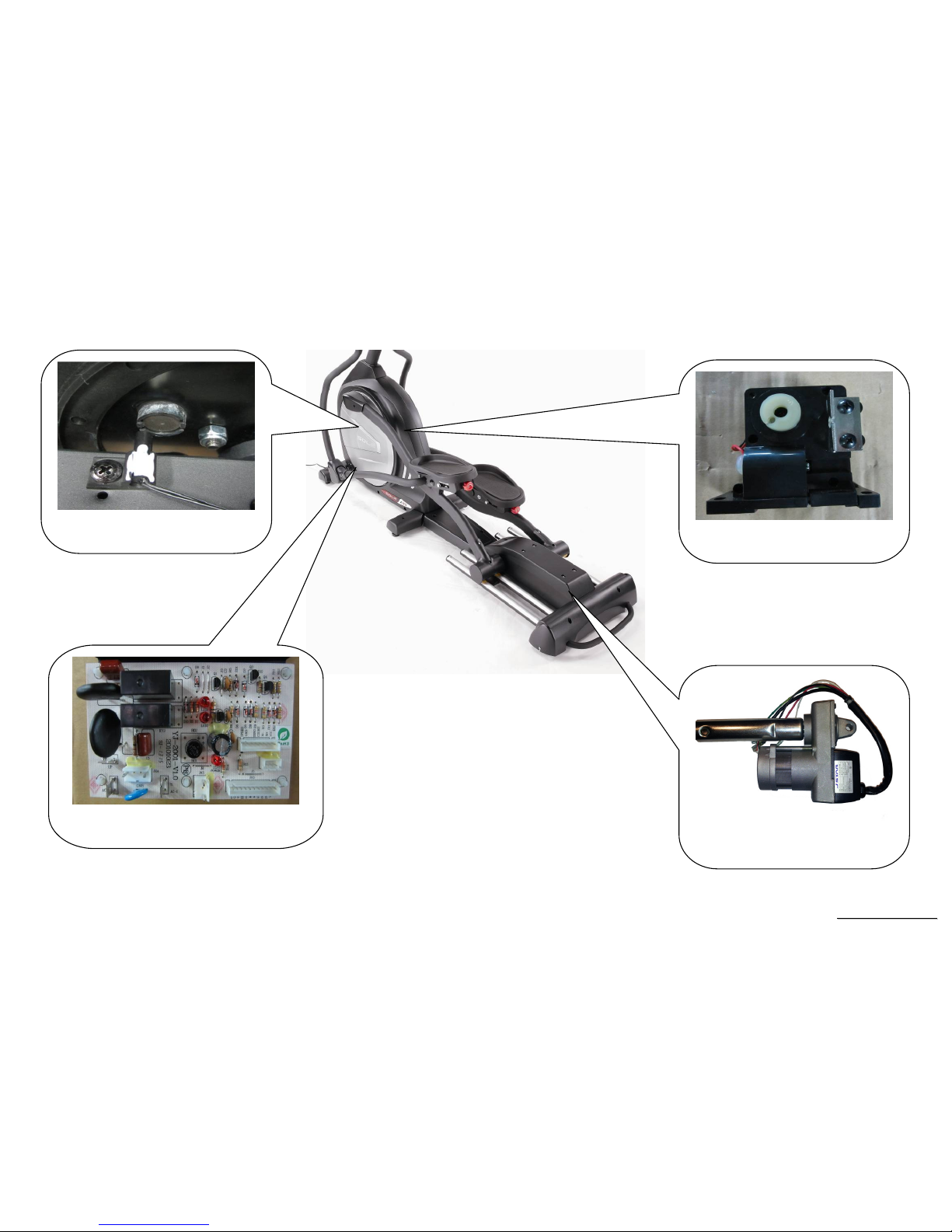
2.2. Lower Controller and Driver
SPEED SENSOR
MOTOR CONTROLLER
TENSION MOTOR
INCLINE MOTOR

SSeerrvviiccee MMaannuuaal
l
-10-
3. Electrical Configurations

SSeerrvviiccee MMaannuuaal
l
-11-
C
ONSOLE:
Interface that controls all functions of the Elliptical.
M
AIN CONTROLLER
:
The circuit board consist of the DC power supply for console、incline driver and tension motor driver, link the console to output appropriate voltages
for tension motor that control the elliptical functions.
T
ENSION MOTOR
:
It can change to increase or decrease resistance level of brake.
I
NCLINE MOTOR:
This is an ac motor. User can to control variable elevation by console within main controller.
G
ENERAL INFORMATION
C
ONSOLE
Contains Key controls and LCD Display.
Main controller Include power supply 、 motor driver control circuit and incline control circuit.
T
ENSION MOTOR
Work voltage: DC 4.5~7.5V
Control resistance increases and decreases.
I
NCLINE MOTOR
This is a 120 volt AC motor.
Have four wires, red, black, white and green.
Has one 3 pins cable of position sensor.
If there is AC voltage on the Red wire (UP) the incline motor will increase the incline.
If there is AC voltage on the Black wire (DOWN) the incline motor will decrease the incline.
The White wire (COM) is neutral.
The green wire is ground.

SSeerrvviiccee MMaannuuaal
l
-12-
4. Elliptical Operation
SSeerrvviiccee MMaannuuaal
l
-13-
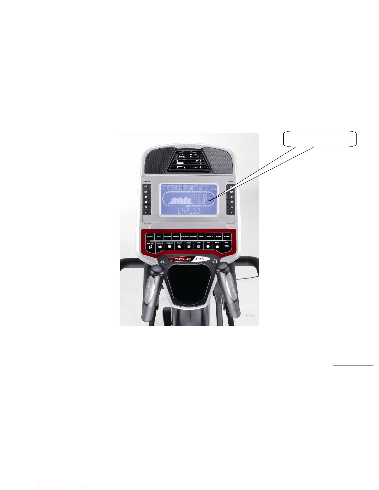
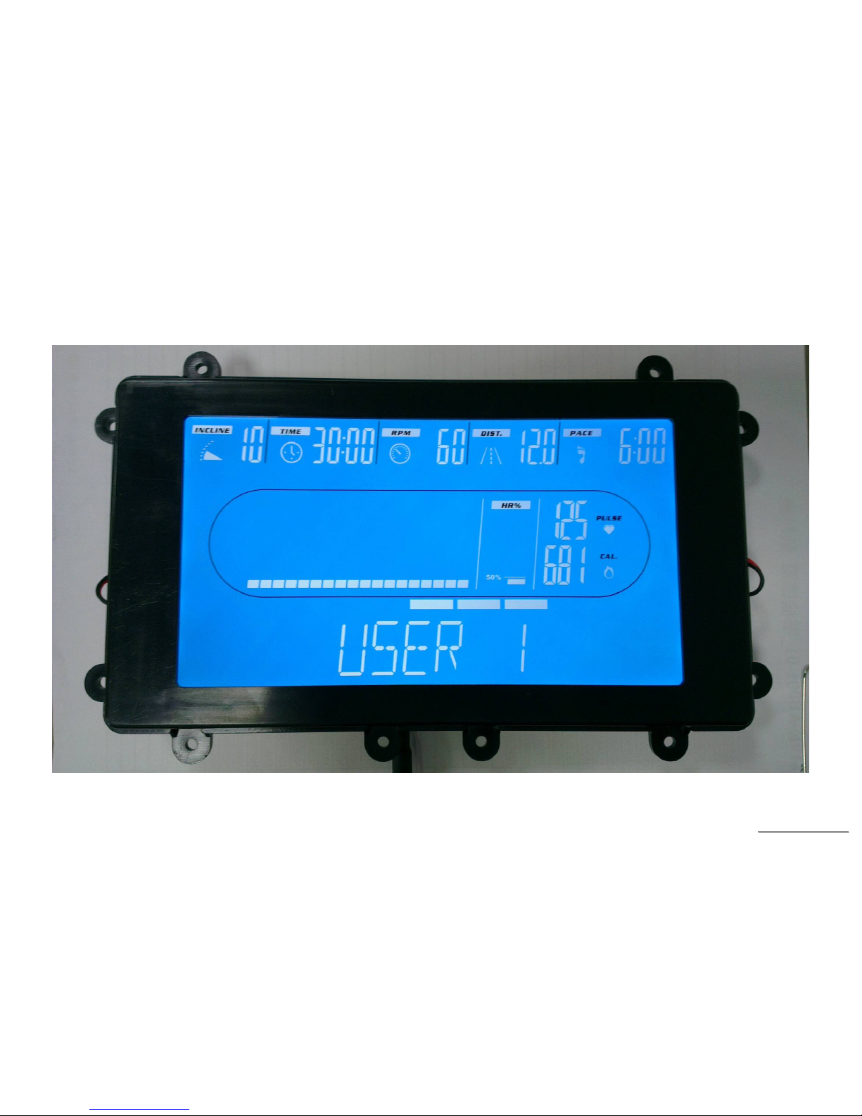
Display Windows
7.5” LCD Display
SSeerrvviiccee MMaannuuaal
l
-14-
LCD Layout

SSeerrvviiccee MMaannuuaal
l
-15-
Operation
Window Display Mode
IDLE MODE
1.1 Each program profile will be displayed on the MESSAGE WINDOW sequentially.
1.2 Heart rate BAR will light up from the bottom and move up. Level, HR% Profile and Track loop will light up from bottom middle and move
counterclockwise.
1.3 DATD WINDOE will display INCLINE= 10,LEVEL= 12,CAL = 681,TIME = 30:00,DISTANCE = 12.0,PACE =6:00,PULSE = 125. It will
get into IDLE MODE without pressing any key after five minutes (not including IDEL MODE, DISPLAY MODE).
DISPLAY MODE
2.1 Pre-set: DISPLAY ON(DISABLE). You could set the DISPLAY ON/OFF by ENGINEERING MODE.
2.2 The console will not get into SLEEP MODE when the set up is “ON”, unless turn off the power. There is no RPM input in IDEL MODE, and enter
to SLEEP MODE after thirty minutes without pressing any key.
2.3 Press the QUICK key to change SLEEP MODE. In IDLE MODE, hold and Press “ENTER”, “STOP”, “DISPLAY” key at the same time for more
than two seconds to switch the SLEEP MODE ON/ OFF. Press “ENTER” key to confirm the set up and jump out to IDEL MODE.
2.4 In DISPLAY MODE, LCD screen will has no display, and backlit will be off. Press any key to wake up the system, and back into IDEL MODE.
2.5 Resistance in SLEEP MODE: Incline =1, FAN system OFF.
CHILD LOCK MODE
3.1 Pre-set: CHILD LOCK OFF (DISABLE). You could set the CHILD LOCK ON/OFF by ENGINEERING MODE.
3.2 The message window will display “CONSOLE LOCKED” twice, and then show the string “ CHILD LOCK-ON PRESS START AND ENTER TO
ENABLE OPERATION ” by blinking when CHILD LOCK setup is ON. You could setup the CHILD LOCK MODE OFF by pressing “START”
and ”ENTER” key for more then two seconds. After that it will enter to IDEL MODE.
3.3 All keys will be no action when CHILD LOCK MODE is active.
EXERCISE MODE(QUICK START)
4.1 In IDEL MODE, press START key enter to MANUAL MODE. The age, weight is presetting value. Time counting is count up from 00:00. All
countable data will count up from “0”, and resistance is count up from “1”.
4.2 You could chose the program by pressing the key: MANUAL、PROGRAM、USER1、USER2、HRC1、HRC2. And then, press “START” key to start
the workout. All parameter will be the preset value.

SSeerrvviiccee MMaannuuaal
l
-16-
PAUSE MODE
5.1 Press “STOP” key enter to PAUSE MODE, and exercise parameters will be recorded. Message window will display “PAUSE”, and upper window
will display the recorded exercise parameter.
5.2 In PAUSE MODE, it will display PAUSE by five seconds, and then display by transit string ”PRESS START TO RESUME OR STOP TO END”
serially.
5.3 It will enter to IDLE MODE after waiting by five minutes without pressing any key in PAUSE MODE.
5.4 The ramp incline level should back to “1” when the resistance level is “1”. The position of tension motor and ramp incline should back to the
preset level before it pause when press “START” key.
END MODE
6.1 The message window will display “ END OF WORKOUT SUMMARY” when the workout is end, and display the workout information by three
minutes.
6.2 END MODE workout information
6.2.1 Display “AVG LEVEL XX”, “AVG SPD XX.X”, “AVG PULSE XX”, AVG INCL XX in message window each three seconds.
6.2.2 The message window will display “PROGRAM END PRESS START TO REPEAT OR STOP TO END OR USER KEY TO SAVE”. Press
START key to restart the same program, STOP key to stop the program, USER key to save the parameter in CUSTOM USER.
6.2.3 LEVEL,INCLINE and PULSE window will display all data average.
6.2.4 CAL window display the total calorie. TIME window display the total exercise time. DIST window display total distance, PACE window display
PACE vaule.
6.3 When the time counting is end, and END MODE display is finished without pressing any key in three minutes. The system will enter IDLE
MODE..
RESET MODE
7.1 In IDLE MODE, press STOP key for more than three seconds will enter to RESET MODE and reset the system. If the system is in CONSOLE
LOCK MODE you have to quit CONSOLE LOCK MODE first, and you can execute the RESET MODE.
7.2 The message window will display RESET two seconds, and finished the reset. After that, the system is in IDLE MODE.

SSeerrvviiccee MMaannuuaal
l
-17-
Function
SPEED
Display the current speed in Kilometer mile per hour.
DISPLAY range is 0.0 to 99.9
WORK range is 0.0~99.9
Incline
Display the incline position from 0 to 20
DISPLAY range is 0 to 99.
WORK range is 0 to 20.
INCLINE preset value is 0 to 20.
Press “UP” or ”DOWN” to adjust incline, each increment and decrement is 1.
LEVEL
Display the incline position from 0 to 20
DISPLAY range is 0 to 999.
WORK range is 0 to 20.
LEVEL preset value is 0 to 20.
Press “UP” or ”DOWN” to adjust incline, each increment and decrement is 1.
TIME
TIME is either COUNT UP or COUNT DOWN. System preset is COUNT UP; if user sets the time then timer is COUNT DOWN.
DISPLAY range is 0:00 to 99:99.
WORK range is 0:00 to 99:59.
COUNT DOWN setup range is 10:00 to 99:00.
When TIME is set, the count will go to zero.
In RUN Mode, press “STOP” button to save value of time and enter “RUN Mode” again that value will continue count up time.

SSeerrvviiccee MMaannuuaal
l
-18-
LAPS
Display the total working laps quantity.
DISPLAY range is 0 to 99.
WORK range is 0 to 99.
Displays total laps quantity.
PACE
1 KM/MILE
DISPLAY range is 00:00 to 99:99.
WORK range is 00:00 to 99:99.
DISTANCE
Display the current distance in kilometer or Mile.
DISPLAY range is 00.0 to 99.9.
WORK range is 00.0 to 99.9.
CALORIES
Displays the cumulative calories burned at any given time during your workout.
DISPLAY range is 00.0 to 999.
WORK range is 00.0 to 999.
PULSE
Displays the heart rate beat by using hand pulse or receiver. When use receiver, a chest belt must be worn.
DISPLAY range is 0 to 999.
WORK range is 40 to 220 BPM.
In RUN Mode, if the treadmill doesn’t have a signal for 8 seconds then display value will become “0 ”.
SSeerrvviiccee MMaannuuaal
l
-19-
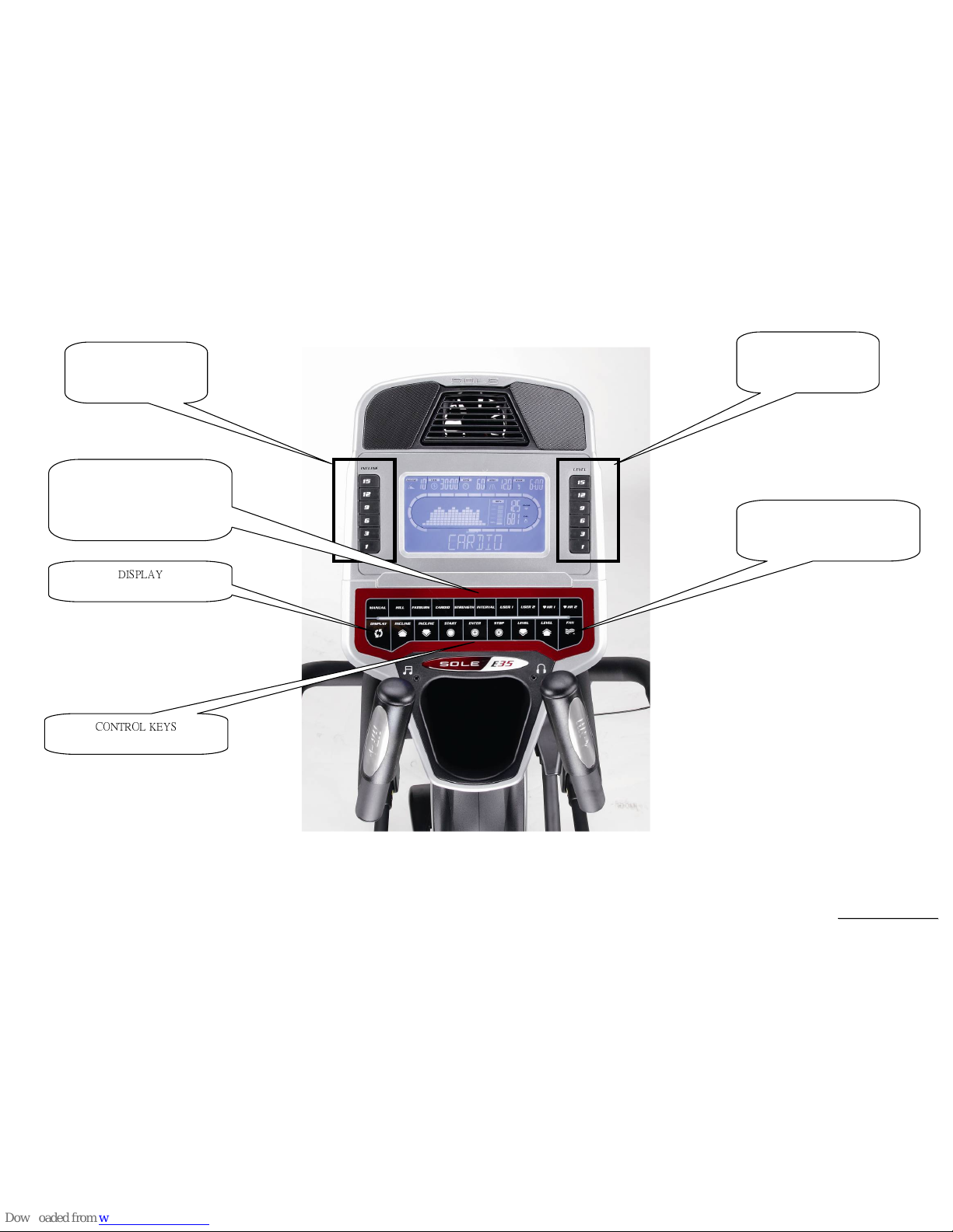
Function Button Locations
Level quick keys
1/3/6/9/12/15
Incline quick keys
1/3/6/9/12/15
Fan Key
Cooling fan switch on or off
PROGRAM BUTTONS
(Manual, Hill, Fat Burn, Strength,
Interval, 2 User, 2HR)
DISPLAY
CONTROL KEYS

SSeerrvviiccee MMaannuuaal
l
-20-
Function Button In Main Mode
READY MODE
STOP button: Non-function.
START button: Pressing “ START ” button to start treadmill, When pressing “START” button, there will be 3 second final count down on window
display, then machine starts running. In MANUAL, treadmill starts at MIN LEVEL .
LEVEL UP button: If user doesn’t enter a setting then this button is non-functional.
LEVEL DOWN button: If user doesn’t enter a setting then this button is non- functional.
INCLINE UP button: If user doesn’t enter a setting then this button is non- functional.
INCLINE DOWN button: If user doesn’t enter a setting then this button is non- functional.
LEVEL RAPID button: 5 preset buttons for rapid speed: 1,2,4,6,8,10.
INCLINE RAPID button: 5preset buttons for rapid incline: 2, 4, 6, 8, 10,12 .
FAN button: It can to control ON/OFF for the fan.
DISPLAY KEY::::
You could select the profile of SPEED or INCLINE by pressing DISPLAY key when select the program (P0~P5, U1~U2).
ENTER KEY:
::
:
Press ENTER key enter to parameter setting, and confirm the every setting by pressing ENTER key. Press START key to finish the setting.
You could change the display of DISPLAY MODE by pressing ENTER key. The preset value is display SPEED profile. And, the switch priority
is SPEED profileINCLINE profileSCAN (SPEED profileINCLINE profileSPEED profile each three seconds).

SSeerrvviiccee MMaannuuaal
l
-21-
RUN MODE
STOP button: press “STOP” button to stop treadmill.
START button: non-functional.
ENTER button: non-functional.
LEVEL UP button: Press the button to increase your level and each increase is 1.
LEVEL DOWN button: Press the button to decrease your level and each decrease is 1.
INCLINE UP button: Press the button to raise position and each increase is 1, the maximum incline position is 20.
INCLINE DOWN button: Press the button to lower position and each decrease is 1, the minimum incline position is 0.
LEVEL RAPID button: Speed will set to 1,3,6,9,12,15. quickly.
INCLINE RAPID button: Incline will set to 1,3,6,9,12,15 position quickly.
Fan button: It can to control ON/OFF for the fan.
DISPLAY KEY::::
Press DISPLAY key to switch the exercise data when you are workout. If the display information is the latest data , press DISPLAY key the
message window will display “DATA SCAN” by two seconds, and then change to auto display every four seconds. The information as
below,
LAPS XX
SPEED XX.XMPH
SPEED XX RPM
LEVEL XX MAX XX ( only in PROGRAM MODE will show this string)
WATT XXX
SEG TIME X:XX (only in HRC MODE will not show this string)
DATA SCAN

SSeerrvviiccee MMaannuuaal
l
-22-
5. Elliptical Unit Block Diagrams
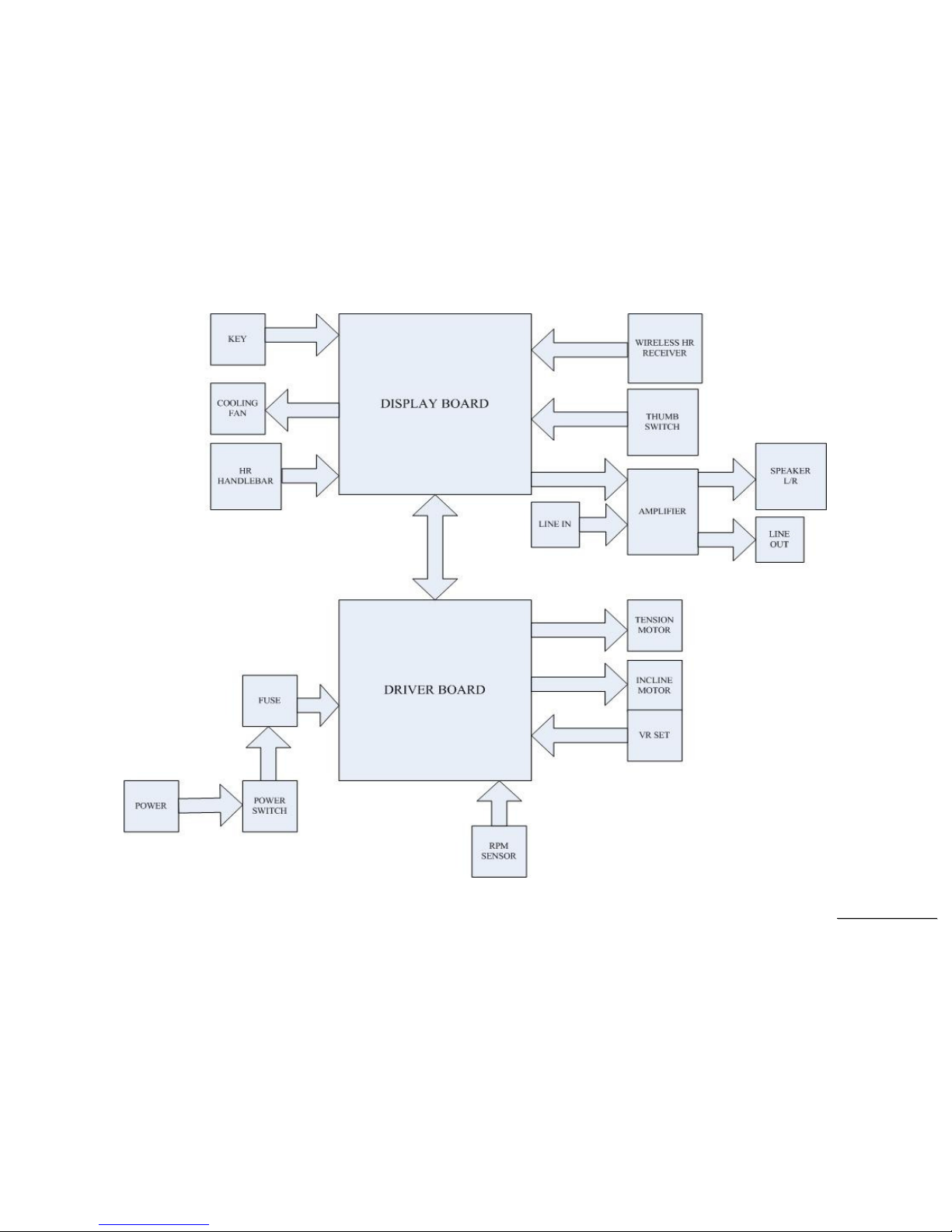
SSeerrvviiccee MMaannuuaal
l
-23-
Elliptical Configuration

SSeerrvviiccee MMaannuuaal
l
-24-
6. Basic Connections and Wiring
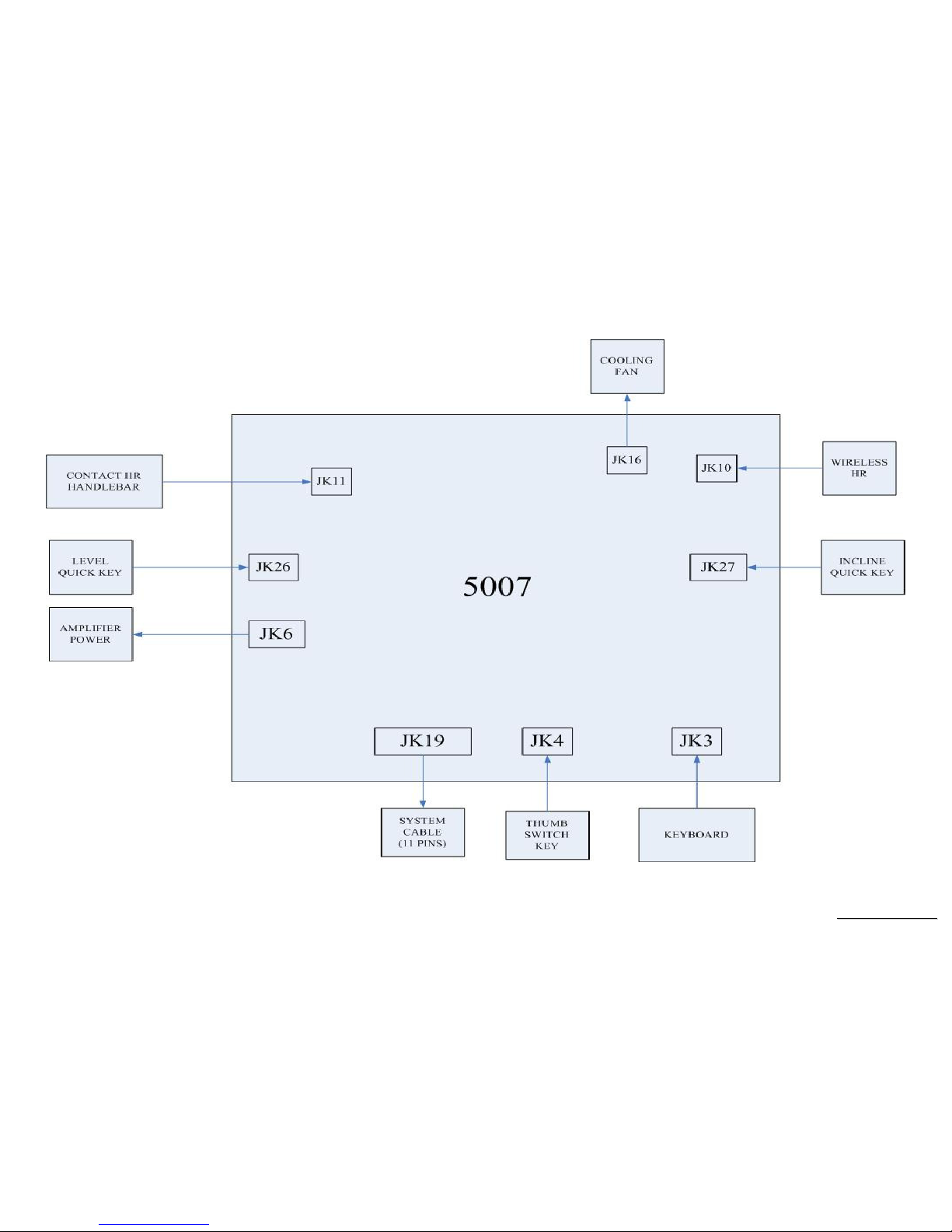
SSeerrvviiccee MMaannuuaal
l
-25-
6.1 Display Board wire Connections
SSeerrvviiccee MMaannuuaal
l
-26-
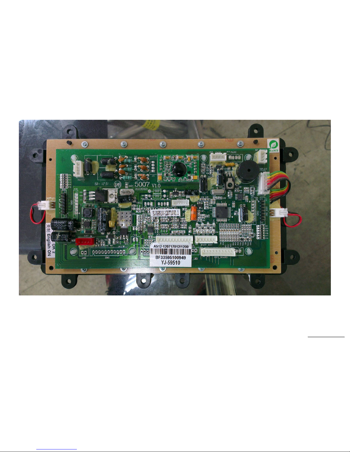
6.2 Display Board PCB Component Locations
PCB Board Top
SSeerrvviiccee MMaannuuaal
l
-27-
PCB Board Bottom
 Loading...