

Dyaco Z10 - Y71, RT86-Y75 Service Manual
ZZ1100--YY7711TTrreeaaddmmiilll
l
SSeerrvviicceeMMaannuuaal
l

WARNING:
ALWAYS UNPLUG THE TREADMILL FROM THE ELECTRICAL
OUTLET BEFORE SERVICING THE UNIT.

SSeerrvviicceeMMaannuuaal
l
TTaabblleeooffCCoonntteenntts
s
TTaabblleeooffCCoonntteennttss1
1
TABLE OF CONTENTS
Table of Contents....................................................................1
Table of Figures......................................................................3
Description .............................................................................4
A ELECTRICAL CONFIGURATION......................................4
1. Z10-Y 71 Treadmill com ponents..................................4
B GENERAL INFORMATION ...............................................5
1. Console.......................................................................5
2. Main controller............................................................5
3. Treadmill motor ..........................................................5
4. Incline motor...............................................................5
Operation................................................................................7
A WINDOW DISPLAY MODE..............................................7
1. OFF Mode...................................................................7
2. READY Mode.............................................................7
3. SLEEP Mode ..............................................................7
4. RUN Mode..................................................................8
B FUNCTION......................................................................9
1. SPEED........................................................................9
2. Incline.........................................................................9
3. TIME..........................................................................9
4. DISTANCE...............................................................10
5. CALORIES...............................................................10
6. PULSE......................................................................10
7. LAPS ........................................................................10
8. SCAN .......................................................................10
C FUNCTION BUTTON IN MAIN MODE ............................11
1. READY MODE........................................................11
2. SLEEP MODE..........................................................12
3. RUN MODE.............................................................12
D CALIBRATION PROCEDURE..........................................14
1. Calibration ................................................................14

SSeerrvviicceeMMaannuuaal
l
TTaabblleeooffCCoonntteenntts
s
TTaabblleeooffCCoonntteennttss2
2
Troubleshooting.................................................................... 15
1. General .....................................................................15
2. Troubleshooting Matrix.............................................16
3. controller debugging form.........................................24
Diagrams and Schematics.....................................................25
APPENDIX A...................................................................... 30
1. TREADBELT ADJUSTMENT................................. 30
APPENDIX B ...................................................................... 32
1. TREADMILL LUBRICATION................................32
APPENDIX C ...................................................................... 33
1. RESET SWITCH RESETTING................................ 33
APPENDIX D...................................................................... 34
1. FUSE REPLACEMENT........................................... 34
APPENDIX E.......................................................................35
1. SPEED SENSOR ADJUSTM ENT............................ 35
2. SERVICE QUESTIONS...........................................35

SSeerrvviicceeMMaannuuaal
l
TTaabblleeooffFFiigguurrees
s
TTaabblleeooffFFiigguurreess3
3
TABLE OF FIGURES
Figure 1 Operational Flowchart..............................................6
Figure 2 Console Layout......................................................26
Figure 3 Mechanical Layout.................................................26
Figure 4 Main Controller information & vo ltages .. .. .. .. ...... ...27
Figure 5 Funct ion JK1 connector on Main Controller...... .. .. .27
Figure 6 Wiring Diagram.....................................................28
Figure 7 Schematic Diagram................................................29
Figure 8 If Treadbel t slips....................................................30
Figure 9 If tread belt shif ts too far to the Right.....................30
Figure 10 If tread belt shif ts too far to the Left.....................31
Figure 11 Resettin g Reset swi tch .........................................33
Figure 12 Fus e repl acement .................................................34

SSeerrvviicceeMMaannuuaal
l
DDeessccrriippttiioon
n
DDeessccrriippttiioonn4
4
DESCRIPTION
A ELECTRICAL CONFIGURATION
Note: Electrical servicing of this treadmill is limited to board
level replacement.
1. Z10 -Y71 TREADMILL COMPONENTS
a) Safety Key:
In dangerous condition, please pull safety key away which is
red. At the some time, the treadmill will be stop.
b) Console:
Interface that control all functions of the treadmill.
c) Main controller:
A circuit board that incorporates the DC power supply and
takes input from the console and sends out appropriate
voltages that control the treadmill functions.
d) Treadmill motor:
This is a variable speed, to control D.C. motor 90 voltage
that powers the main running belt.
e) Incline motor:
An AC reversing motor that sets the incline of the treadmill.

SSeerrvviicceeMMaannuuaal
l
DDeessccrriippttiioon
n
DDeessccrriippttiioonn5
5
B GENERAL INFORMATION
1. CONSOLE
a) Contains 3 windows which are twenty rows “dots” (8high)
indicate each segment of a workout.
2. MAIN CONTROLLER
a) Contains power supply and control circuits
3. TREADMILL MOTOR
a) Variable speed reversing 0-90 volt DC motor.
b) Have three wires red, black and green.
c) If there is DC voltage on the Red wire (M+) the treadmill
motor will turn clockwise.
d) If there is DC voltage on the Black wire (M-) the treadmill
motor will turn counter-clockwise
e) The green wire is ground.
4. INCLINE MOTOR
a) Reversing 115 volts AC motor.
b) Have four wires, red, black, white and green.
c) Has one 3 pins cable of position sensor.
d) If there is AC voltage on the Red wire (DOWN) the incline
motor will increas e the incline.
e) If there is AC voltage on the Black wire (UP) the incline motor
will decrease the incline.
f) The White wire (COM) is neutral.
SSeerrvviicceeMMaannuuaal
l
DDeessccrriippttiioon
n
DDeessccrriippttiioonn6
6
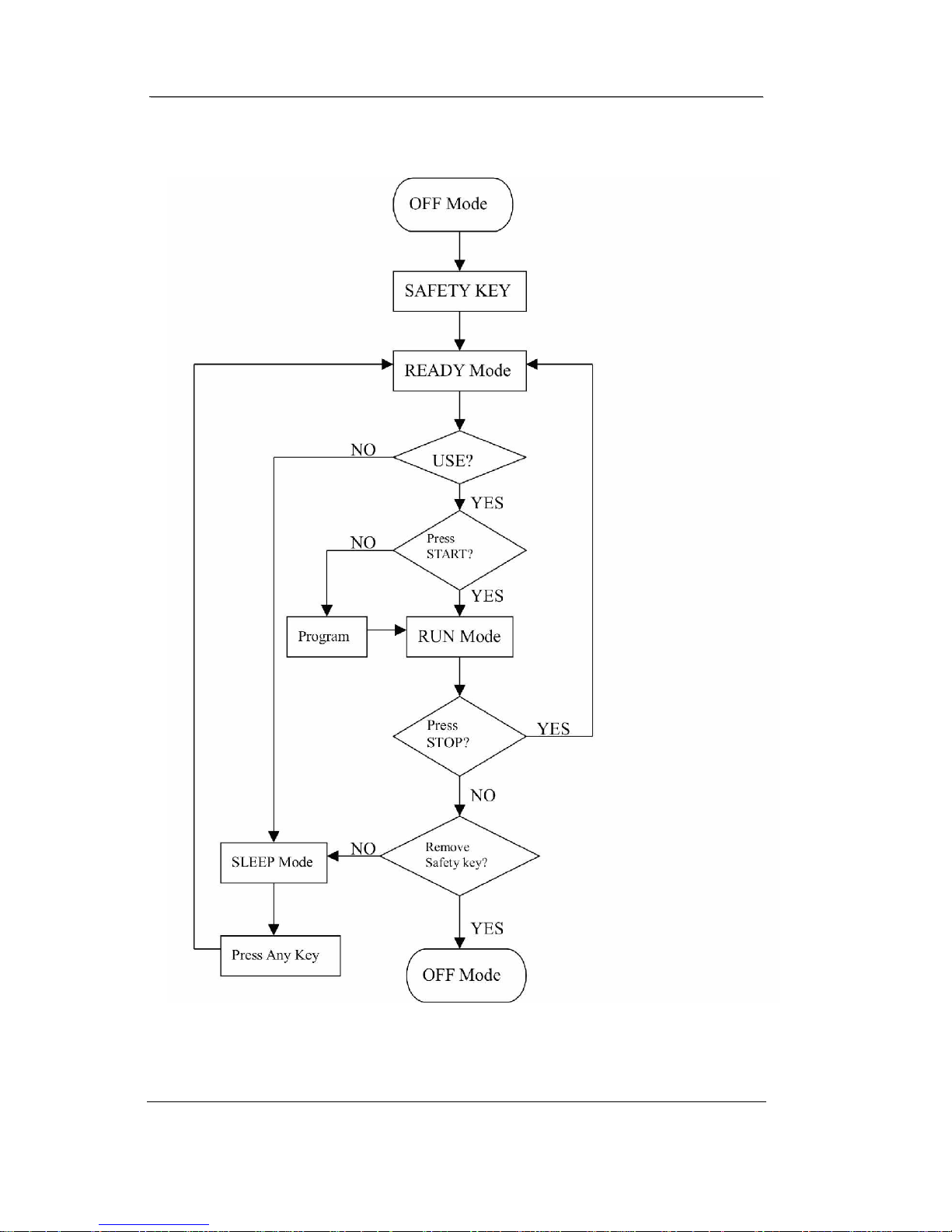
Figure 1 Operational Flowchart

SSeerrvviicceeMMaannuuaal
l
OOppeerraattiioon
n
OOppeerraattiioonn7
7
OPERATION
A WINDOW DISPLAY MODE
1. OFF MODE
a) When user doesn’t insert the SAFETY KEY on the console, the
treadmill enters the OFF Mode and Dot Matrix windows will
display. Please install safety key to start.
2. READY MODE
a) When the treadmill has been power on and set the safety key on
the console, all light will be to light.
b) Console will display current software version in dot matrix
window; DISTANCE window displays total accumulated
working distance; TIME window displays total accumulated
working time.
c) In READY Mode, if user doesn’t press any button for 30
minutes it will automatically turn off (blank out).
d) Press START button to start treadmill on P0(Manual) Mode.
e) Press PROGRAM UP/DOWN button to select program P1~U2
3. SLEEP MODE
a) When nobody to use the treadmill, the console will into SLEEP
Mode. If any buttons are pressed, the treadmill enters READY
Mode.

SSeerrvviicceeMMaannuuaal
l
OOppeerraattiioon
n
OOppeerraattiioonn8
8
4. RUN MODE
a) In RUN Mode, pressing the “STOP” button or pull away the
safety key that will cause the treadmill stop instantly and enter
OFF Mode.
b) Display will automatically shift every 3 seconds.
c) Press “SELECT” button to exchange the displaying of LED
which includes laps of Track, Incline profile an d Speed profile.
d) Enter button: Excha n ge display windows.

SSeerrvviicceeMMaannuuaal
l
OOppeerraattiioon
n
OOppeerraattiioonn9
9
B FUNCTION
1. SPEED
a) DISPLAY range is 0.0 to 99.9 MPH.
b) WORK range is 0.6 to 10.0 MPH.
c) Press “FAST” or ”SLOW” to adju st speed, each increment and
decrement is 0.1mph/kph.
2. INCLINE
a) Display the incline position from 0 to 15.
b) DISPLAY range is 0 to 999.
c) WORK range is 0 to 15.
d) INCLINE preset value is 0 to 15.
e) Press “UP” or ”DOWN” to adjus t incline, each increment and
decrement is 1.
3. TIME
a) In RUN Mode, TIME divides into COUNT UP and COUNT
DOWN. System preset is COUNT UP; if user sets the time
then timer is COUNT DOWN.
b) DISPLAY range is 0:00 to 99:99.
c) WORK range is 0:00 to 99:59.
d) COUNT DOWN setup range is 10:00 to 99:59.
e) When TIME is set, the count will go to zero.
 Loading...