

Dyaco FT98A-YT41 Service Manual
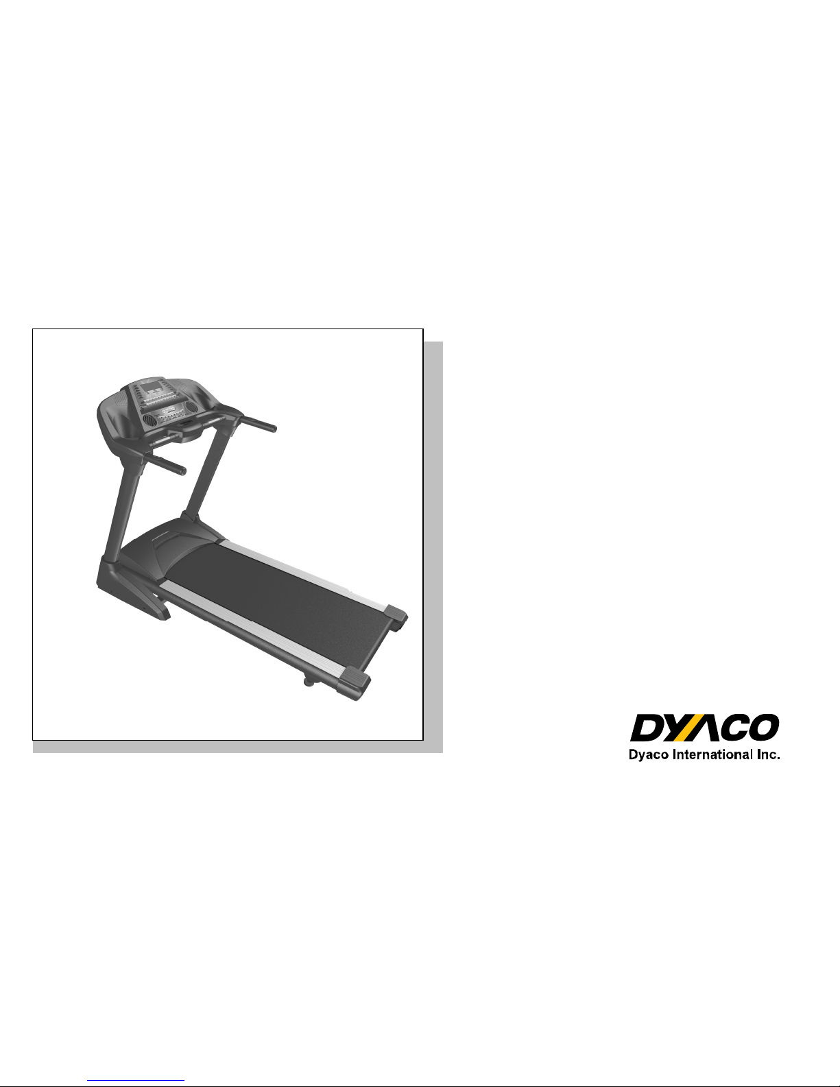
FT98A-YT41
Treadmill
Service Manual

SSeerrvviiccee MMaannuuaal
l
1
-------------------------------------------Table of Contents-------------------------------------------
1. Treadmill Outlines
2. Electronic Parts
2.1 Upper Controllers
2.2 Lower Controller and driver
3. Electrical Configuration
4. Product Operation
5. Unit Block Diagrams
6. Basic Connections and Wiring
6.1 Display Board Wire Connections
6.2 Display Board PCB Component Locations
6.3 Driver Board Wire Connections
6.4 Driver Board PCB Component Locations
6.5 Driver Board LED Indicator Locations
6.6 Controller Indicator LED Debugging
6.7 Driver Board Function
6.8 Main connector of the console
7. Product Safety Instructions
7.1 Important Safety Instructions
7.2 Important Electrical Instructions
7.3 Important Grounding Instructions
8. Error Messages / Troubleshooting for Electronic Issues
8.1 Error Message::::LS1/LOW SPEED
8.2 Error Message: E1
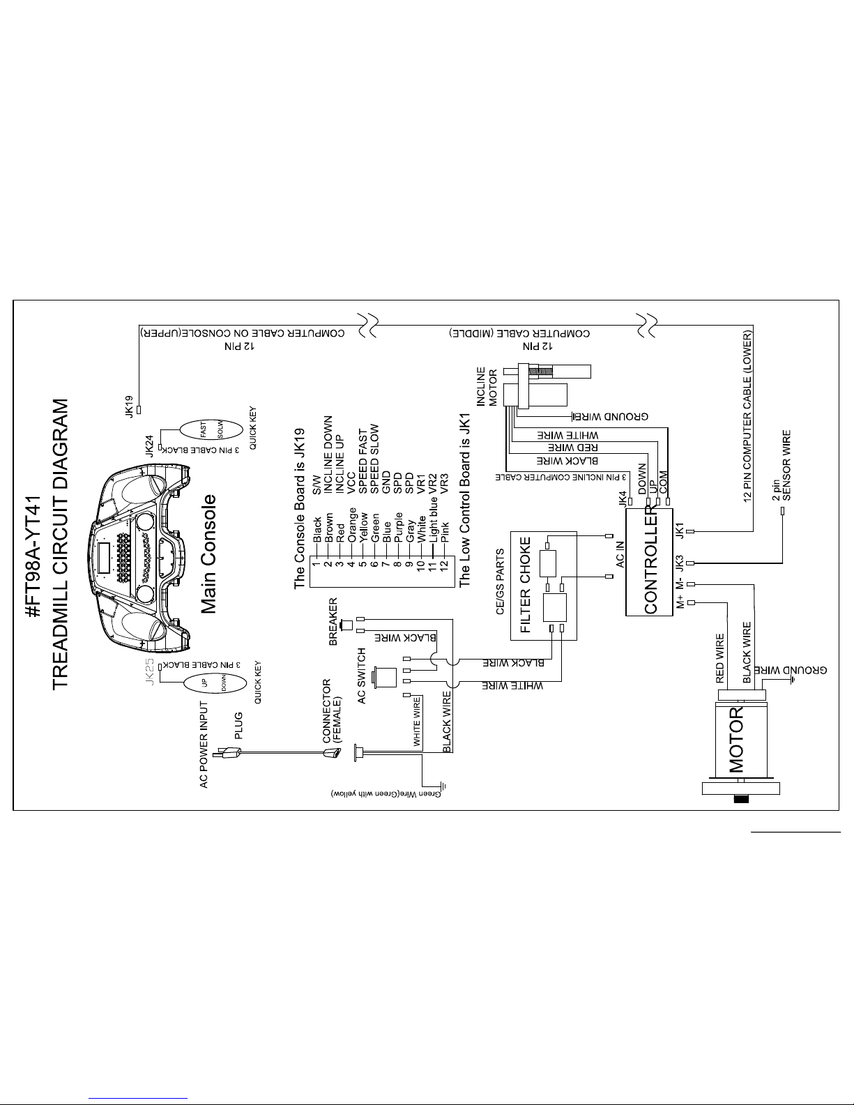
8.3 Circuit Diagram
8.4 Calibration Procedure
8.5 Fuse Replacement
9. Folding/Unfolding and Transport
10. General Maintenance
10.1 Tread Belt and Deck
10.2 Service Troubleshooting Checklist – Diagnosis Guide
11. Installation of the Incline Motor

SSeerrvviiccee MMaannuuaal
l
2
12. Disassembling and Assembling of Parts
12.1 Lower Controller Replacement
12.2 Console Replacement
12.3 Motor Replacement
12.4 Breaker Replacement
12.5 AC Power Switch Replacement
12.6 Front/ Rear Roller Replacement
12.7 Running Deck/ Belt & Cushion Replacement
12.8 Speed Sensor Replacement
12.9 Incline Motor Replacement
SSeerrvviiccee MMaannuuaal
l
3

SSeerrvviiccee MMaannuuaal
l
4
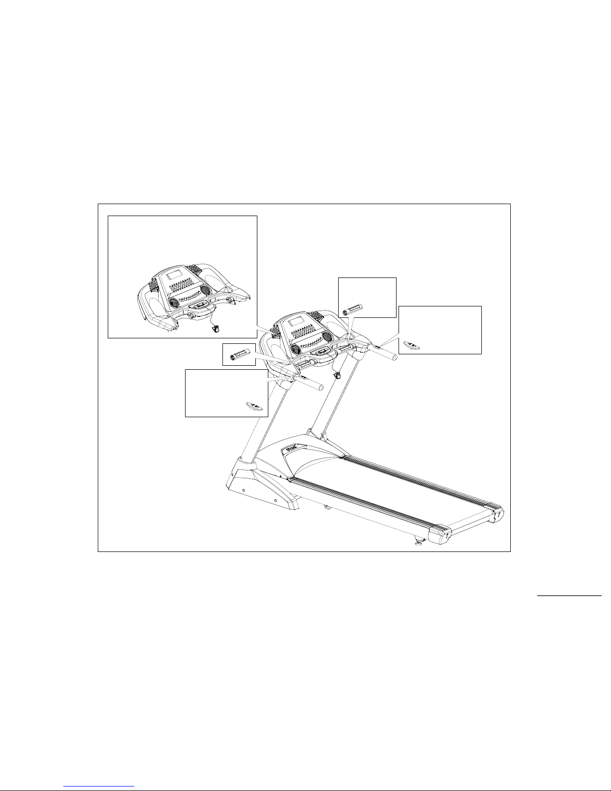
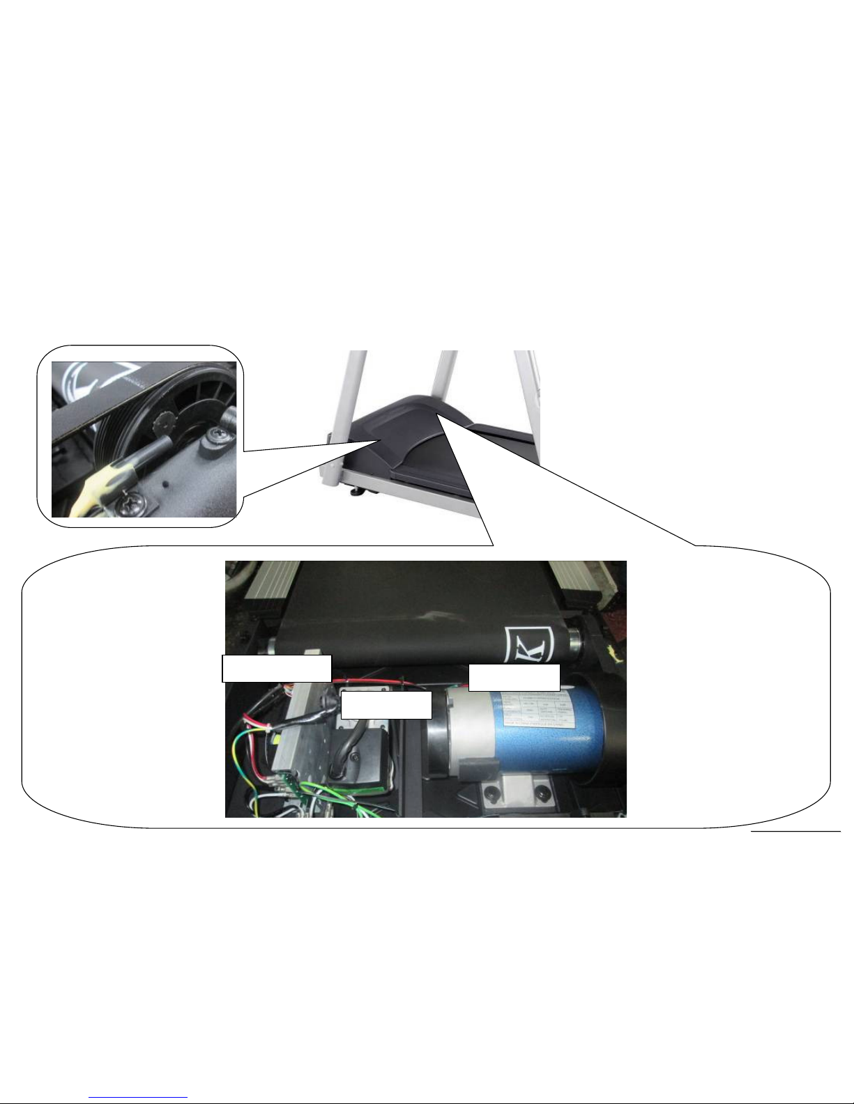
1. FT98A Treadmill Outlines
SSeerrvviiccee MMaannuuaal
l
5
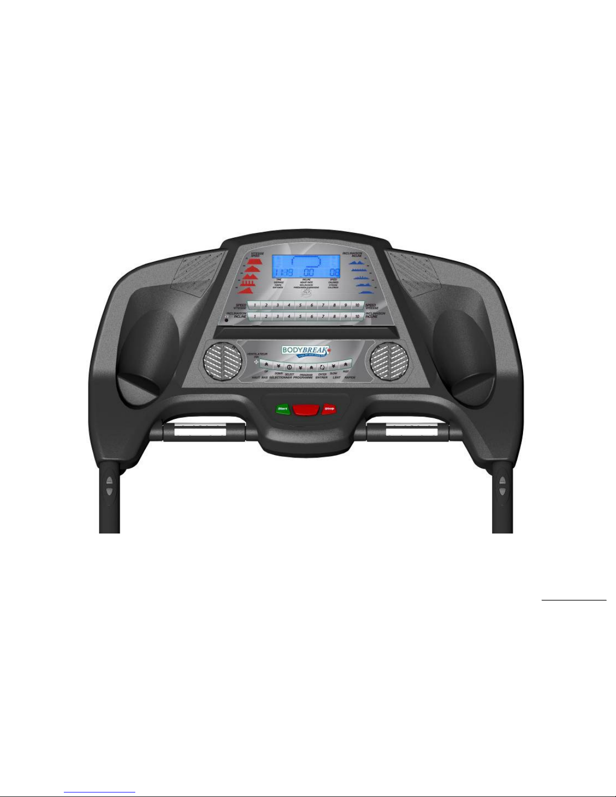
Console
Incline
adjustment
button
Speed
adjustment
button
Hand Pulse
Sensor
SSeerrvviiccee MMaannuuaal
l
6
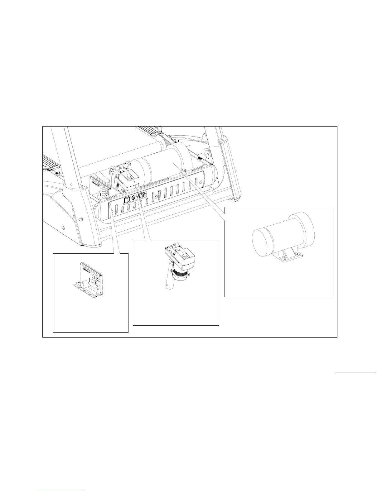
Lower
Controller
Incline Motor
Driving Motor
SSeerrvviiccee MMaannuuaal
l
7

SSeerrvviiccee MMaannuuaal
l
8
2. Electronic Parts
SSeerrvviiccee MMaannuuaal
l
9
2.1 Upper Controllers
DISPLAY
Hand Pulse
Heart Sensors
Hand Pulse
Heart Sensors
SSeerrvviiccee MMaannuuaal
l
10
2.2. Lower Controller and Driver
DC MOTOR
Motor Controller
INCLINE MOTOR

SSeerrvviiccee MMaannuuaal
l
11
3. Electrical Configurations

SSeerrvviiccee MMaannuuaal
l
12
S
AFETY KEY
:
To fits on the Console that activate all functions. If no safety key, console can not be controlled.
C
ONSOLE:
Interface that controls all functions of the treadmill.
M
AIN CONTROLLER
:
The circuit board consist of the DC power supply for console、incline driver and DC motor driver, link the console to output appropriate voltages for
motor that control the treadmill functions.
T
READMILL MOTOR
:
This is a variable speed for DC motor. To control the 0 –180(230VAC) or 0-90(120VAC) voltages on the main controller, it can to increase or
decrease speed of running belt.
G
ENERAL INFORMATION
C
ONSOLE
Contains Key controls and LCD Display.
Main controller Include power supply 、 motor driver control circuit and incline control circuit.

SSeerrvviiccee MMaannuuaal
l
13
T
READMILL MOTOR
It’s a variable speed on 0-180(0-90) volt DC motor.for 230V~ OR (120V~ model)
Have three wires red, black and green.
If there is DC voltage on the Red (white) wire (M+) the treadmill motor will turn clockwise.
If there is DC voltage on the Black wire (M-) the treadmill motor will turn counter-clockwise.
The higher the voltage the faster the motor turns
The green wire is ground.
N
OTICE BEFORE OPERATION
:
The treadmill will increase or decrease speed slowly. It means that it will take you a little time to reach the speed you adjusted. When you work
on the treadmill, you must check the emergency switches both on left and right side are turned on, and turn around the switch to check it is off.
Also, check the safety key is put on properly, and the clip is on your cloth. Any of the devices above mentioned is incorrect, and then the
machine couldn’t work.

SSeerrvviiccee MMaannuuaal
l
14
4. FT98A Treadmill Product Operation
SSeerrvviiccee MMaannuuaal
l
15
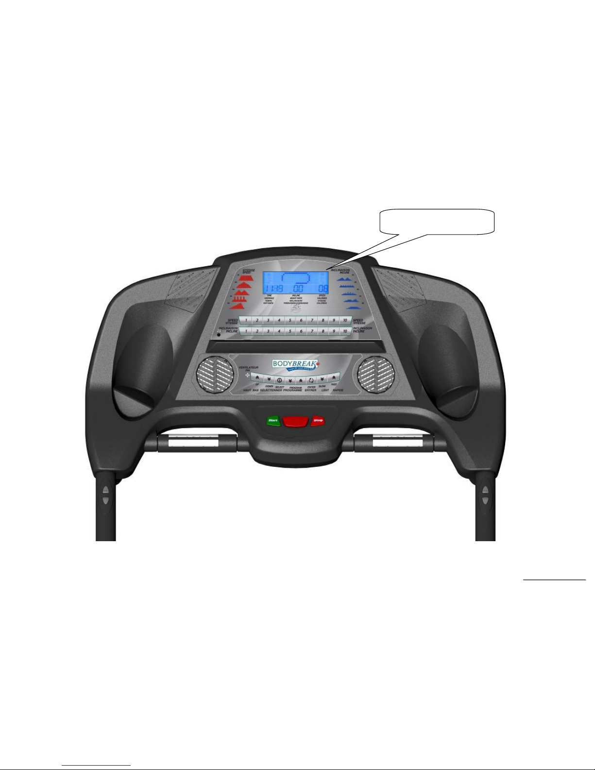
Display Windows
LCD Function display locations
LCD Display

SSeerrvviiccee MMaannuuaal
l
16
Operation
Window Display Mode
OFF Mode
When user doesn’t insert the SAFETY KEY on the console the treadmill enters the OFF Mode LCD Display off.
READY Mode
When the treadmill is ON and SAFETY KEY is inserted in console the treadmill enters the READY Mode. Press START button to start treadmill on
Manual Mode.
SLEEP Mode
In SLEEP Mode, if anyone
button is pressed then the treadmill enters READY Mode.
RUN Mode
In RUN Mode, pressing the “STOP” button and removing the SAFETY KEY will cause the treadmill stop instantly or enter OFF Mode.
Function
SPEED
Display the current speed in Kilometer or Mile per hour.
DISPLAY range is 0.00 to 99.9 km/h.
WORK range is 1.0 to 16.0 km/h (0.6~10MPH)
Press “FAST” or ”SLOW” to adjust speed, each increment and decrement is 0.1 km/h(mph).
TIME
TIME is either COUNT UP or COUNT DOWN.
DISPLAY range is 0:00 to 99:99.
WORK range is 0:00 to 99:59.
COUNT DOWN setup range is 10:00 to 99:00.
In RUN Mode, press “STOP” button to save value of time and enter “RUN Mode” again that value will continue count up time.
DISTANCE
Display the current distance in kilometer or Mile.
DISPLAY range is 0.00 to 999.9.
WORK range is 0.00 to 99.99.
CALORIES
Displays the cumulative calories burned at any given time during your workout.
DISPLAY range is 0.0 to 999
WORK range is 0.0 to 999

SSeerrvviiccee MMaannuuaal
l
17
PULSE
Displays the heart rate beat by using hand pulse or receiver. When use receiver, a chest belt must be worn.
DISPLAY range is 0 to 999.
WORK range is 30 to 210.
In RUN Mode, if the treadmill doesn’t have a signal for 8 seconds then display value will become no display.
SSeerrvviiccee MMaannuuaal
l
18
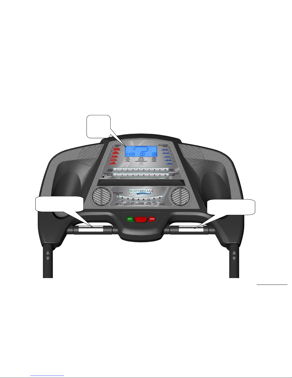
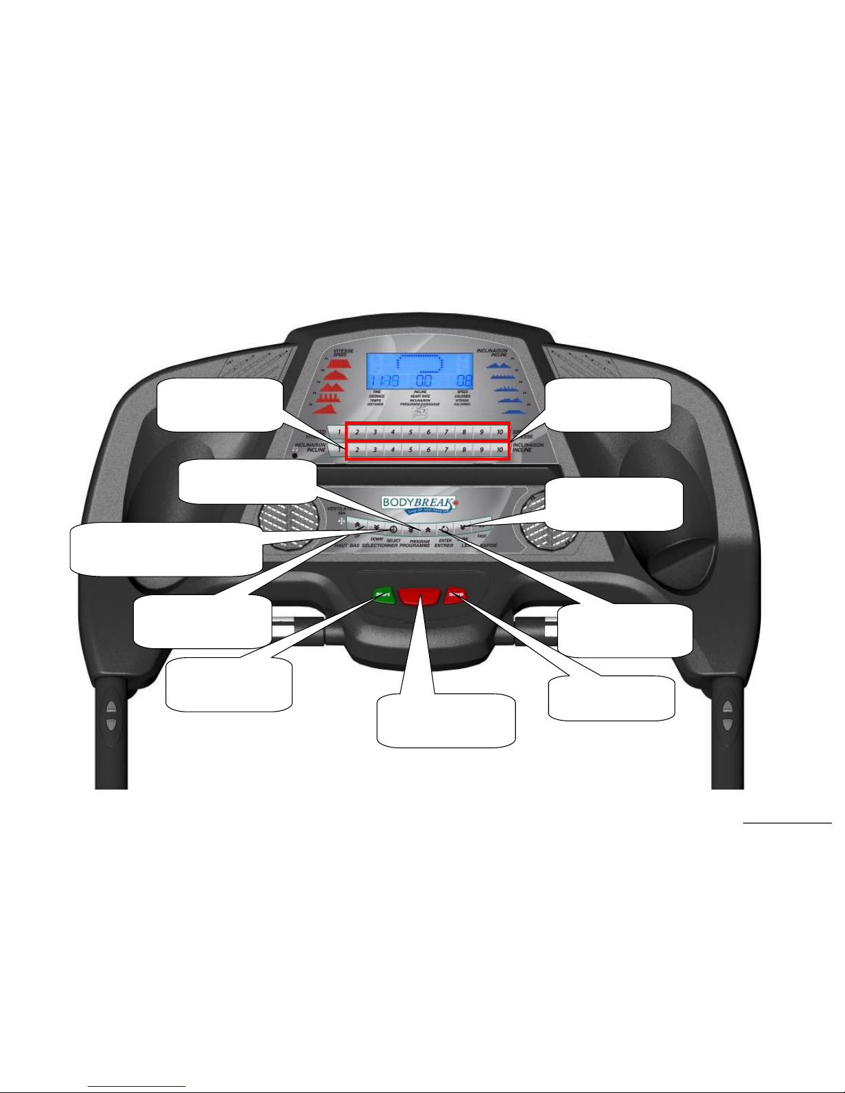
Function Button Locations
Speed quick keys
1/2/3/4/5/6/7/8/9/10
FAST/Slow Key
Adjustment Speed
Enter Key
Set data function
STOP Key
End workout
Safety Key
Emergency function
Incline quick keys
1/2/3/4/5/6/7/8/9/10
PROGRAM ︽︾Key
Choose Program
Up/down Key
Adjustment incline
START Key
To workout
Select Key
Switch Speed or Grace profile

SSeerrvviiccee MMaannuuaal
l
19
Function Button In Main Mode
READY MODE
SAFETY KEY: Fit safety key in right position to power on the computer. When safety key is pulled away from its position, the computer will be
automatically shut down.
START button: Pressing “ START ” button to start treadmill, When pressing “START” button, there will be 3 second final count down on window
display, then machine starts running. In MANUAL, treadmill starts at MIN SPEED and treadmill starts at program preset value in PROGRAM.
STOP button:
Pressing “ STOP ” button to stop treadmill, When pressing “STOP” button, Slowly lower the speed to run with stop
.
ENTER button: Press “ENTER” button to change each function. MANUAL can set using time, Pre-set PROGRAM can set using time and speed,
FAST button: If user doesn’t enter a setting then this button is non-functional.
SLOW button: If user doesn’t enter a setting then this button is non- functional.
PROGRAM ︽︽︽︽button: While program setting, pressing this button changes the PROGRAM, with the sequence as below:
P0→P1→P2→P3→P4→P5→USER1→USER2→HRC1→HRC2
↑
_______________________________________________
↓
PROGRAM ︾︾︾︾ button: While program setting, pressing this button changes the PROGRAM, with the sequence as below:
HRC2→HRC1→USER2→USER1→P5→P4→P3→P2→P1→P0
↑
_______________________________________________
↓
SPEED RAPID button: 10preset buttons for rapid speed: 1kph(MPH), 2kph(MPH), 3kph(MPH),4kph(MPH), 5kph(MPH),6kph(MPH),
7kph(MPH), 8kph(MPH), 9kph(MPH),10kph(MPH)
INCLINE RAPID button: 10preset buttons for rapid INCLINE: 1, 2, 3,4,5,6,7,8,9,10

SSeerrvviiccee MMaannuuaal
l
20
RUN MODE
SAFETY KEY: When safety key is pulled away from its position, the computer will be automatically shut down.
STOP button: press “STOP” button to stop treadmill.
SELECT button: While running P1~U2 program, pressing this button switches between SPEED profile and GRACE profile.
FAST button: Press the button to increase your speed and each increase is 0.1kph. If button is pressed continuously then speed increases to
MAX SPEED quickly.
SLOW button: Press the button to decrease your speed and each decrease is 0.1kph. If button is pressed continuously then speed decreases to
MIN SPEED quickly.
SPEED RAPID button: Speed will set to , 1kph(MPH), 2kph(MPH),) 3kph(MPH ),4kph(MPH,5kph(MPH), 6kph(MPH)
7kph(MPH),8kph(MPH),9kph(MPH),10kph(MPH)
INCLINE RAPID button: 10preset buttons for rapid INCLINE: 1, 2, 3,4,5,6,7,8,9,10

SSeerrvviiccee MMaannuuaal
l
21
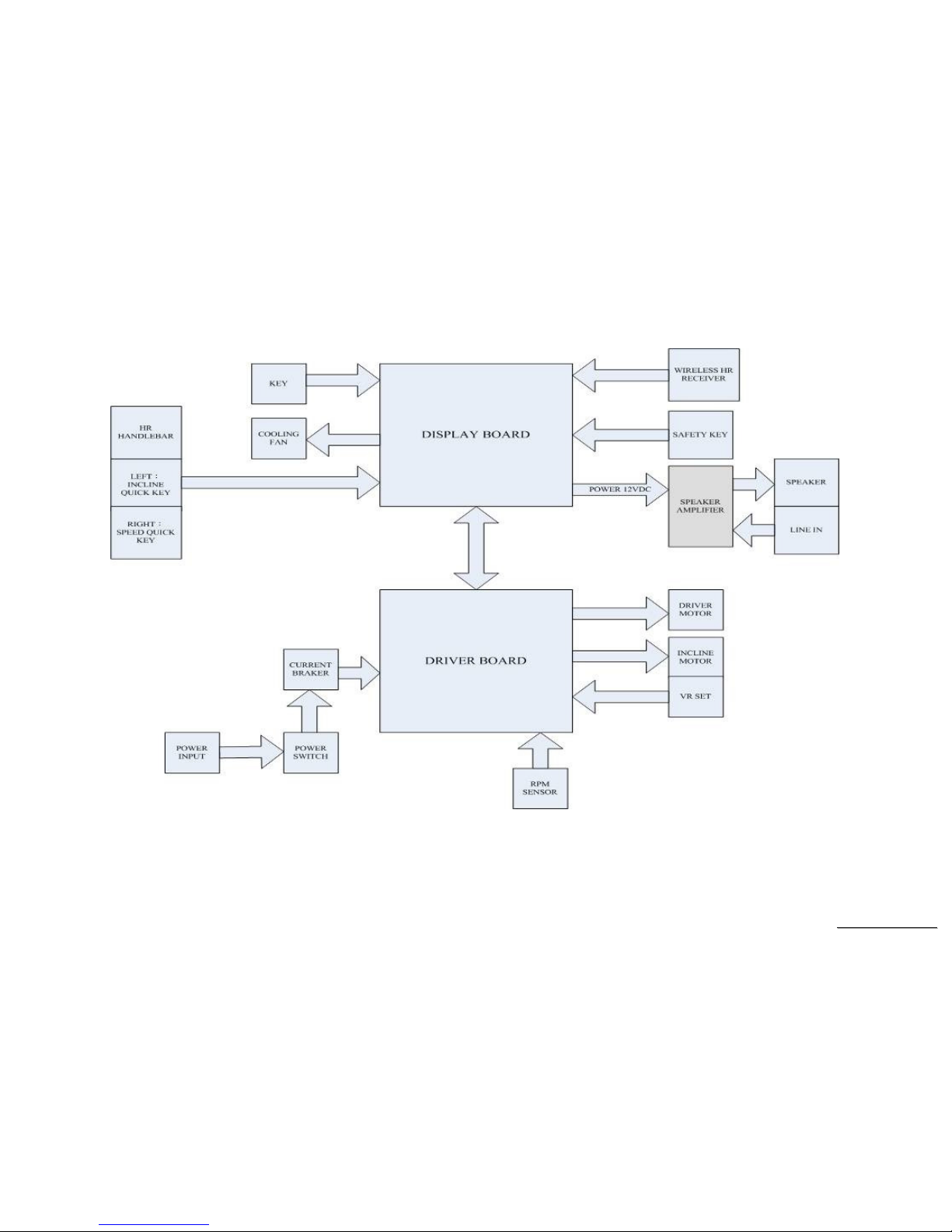
5. FT98A Treadmill Unit Block Diagrams
SSeerrvviiccee MMaannuuaal
l
22
Treadmill Configuration

SSeerrvviiccee MMaannuuaal
l
23
6. FT98A
Treadmill Basic Connections and Wiring
SSeerrvviiccee MMaannuuaal
l
24
6.1 Display Board wire Connections
SSeerrvviiccee MMaannuuaal
l
25
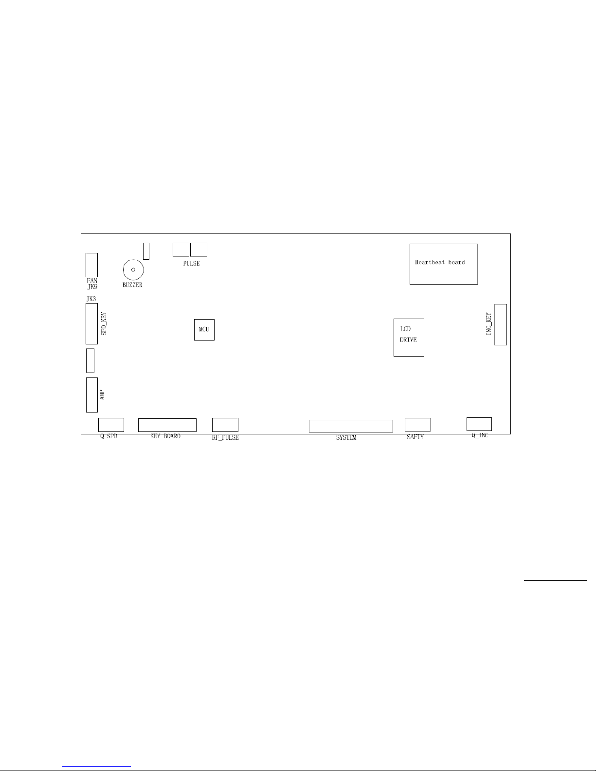
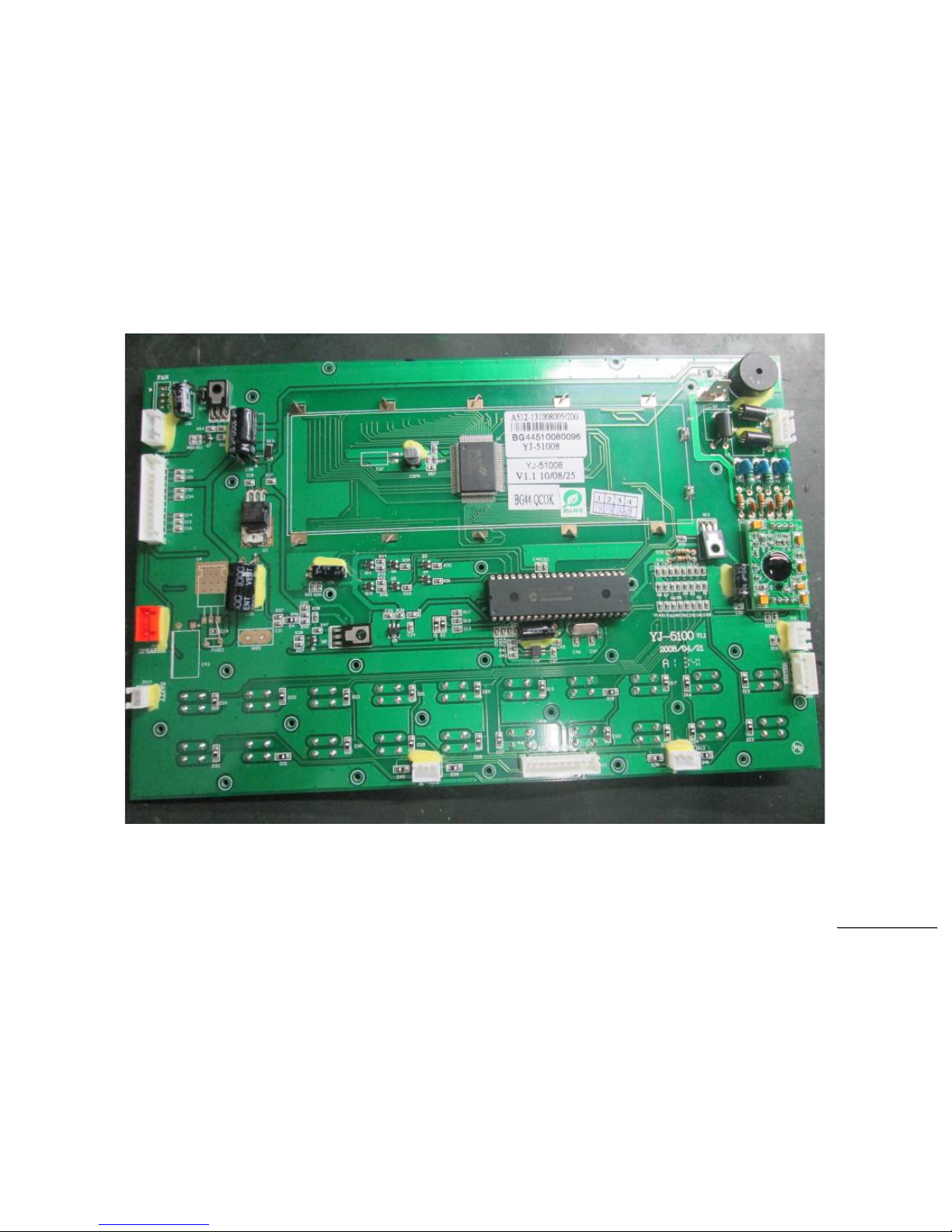
6.2 Display Board PCB Component Locations
PCB Board Top
SSeerrvviiccee MMaannuuaal
l
26
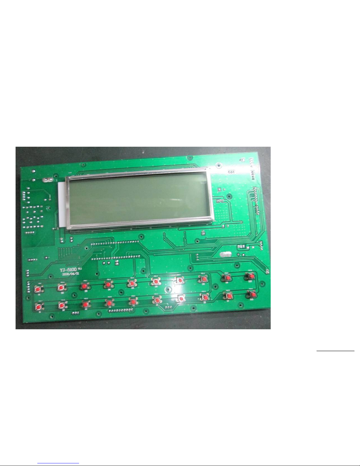
PCB Board Bottom
 Loading...