

DXO TELECOM XV1000 User Manual
VDSL Modem XV1000
User Guide
- Installation & Operation

Table of Contents
Chapter 1. Introduction........................................................................................................................................1
1. Introduction of XV1000 VDSL Modem.........................................................................................................1
2. Applications................................................................................................................................................ 1
3. Easy Installation .........................................................................................................................................1
4. Low Cost .................................................................................................................................................... 1
5. Application Area .........................................................................................................................................1
6. Name of each part and function .................................................................................................................. 2
XV1000 VDSL Modem Front Panel .........................................................................................................2
LEDs of XV1000 VDSL Modem............................................................................................................... 2
XV1000 VDSL Modem Real Panel ..........................................................................................................2
Function of XV1000 VDSL Modem Port...................................................................................................2
7. XV1000 VDSL Modem Specification...........................................................................................................3
Chapter 2. Before Installation..............................................................................................................................3
1. Safety Check..............................................................................................................................................3
Electrical safety.......................................................................................................................................3
Site of Installation....................................................................................................................................3
2. Telephone Network Service/PC Specification.............................................................................................. 3
Telephone Network Service..................................................................................................................... 3
PC Specification ...................................................................................................................................... 3
3. Preparing Cables........................................................................................................................................4
Cables used for XV1000 VDSL modem................................................................................................... 4
RJ-11 Telephone Cable....................................................................................................................4
RJ-45 UTP Ethernet Cable...............................................................................................................4
Chapter 3. Installing XV1000 VDSL modem........................................................................................................ 5
1. Environment ............................................................................................................................................... 5
2. Packing list.................................................................................................................................................5
3. Modem Installation......................................................................................................................................6
¨ç Drawing network configuration diagram............................................................................................ 6
¨è Installing the stool............................................................................................................................7
¨é Disconnecting the power cord..........................................................................................................7
¨ê Connecting the telephone line..........................................................................................................7
¨ë Connecting the PC........................................................................................................................... 8
¨ì Applying power................................................................................................................................8
¨í Checking the connection status........................................................................................................8
VDSL line connection status ............................................................................................................8
PC connection status....................................................................................................................... 8
Telephone connection status............................................................................................................9
Chapter 4. Trouble Shooting................................................................................................................................9
1. Items to check before asking for technical support ......................................................................................9
2. Problems and solutions............................................................................................................................... 9
Category of problems..............................................................................................................................9
Problems related to power ...............................................................................................................9
Problems related to network connection...........................................................................................9
Chapter 5. Glossary........................................................................................................................................... 10

NOTE : FCC
This equipment has been tested and found to comply with the limits for a Class B digital device,
Pursuant to Part 15 of the FCC rules.
These limits are designed to provide reasonable protection against harmful interface in a residential installation.
This equipment generates, uses and can radiate radio frequency energy and, if not installed and used in
accordance with the instructions, may cause harmful interference to radio communications.
However, there is no guarantee that interference will not occur in a particular installation.
If this equipment does cause harmful interference to radio or television reception, which can be determined by turning
the equipment off and on, the user is encouraged to try to correct the interference by one or more of the following
Measures:
--Reorient or relocate the receiving antenna.
--Increase the separation between the equipment and receiver.
--Connect the equipment into an outlet on a circuit different from that to which the receiver is connected.
--Consult the dealer or an experienced radio/TV technician for help.
CAUTION: Changes or modifications not expressly approved by the manufacturer responsible for compliance could void the
user’s authority to operate the equipment
NOTE : UL
Do not use upside down.
Operator or installer must remove power and TNV connections before handling the equipment.
Caution – To reduce the risk of fire, use only No. 26 AWG or larger telecommunication line cord.

XV1000 Modem User Guide
Chapter 1. Introduction
This chapter explains major features, operation procedure, hardware configuration and specification of XV1000, the
DXO VDSL Modem.
l Introduction of XV1000 VDSL Modem
l Name and function of each part
l Specification of XV1000
1. Introduction of XV1000 VDSL Modem
XV1000 VDSL modem allows the PC to connect to the internet or other multimedia service network using the
conventional telephone network (PSTN).
Unlike the ADSL modem, XX1000 provides 10Mbps data transmission rate. Telephone conversation is never
interrupted while the modem is in use.
Features that XV1000 offers are as follows:
2. Applications
Features that XV1000 offers include connection to the internet, interactive communication, e-mails, file transfer,
download/upload of motion pictures and others.
3. Easy Installation
Installation of XV1000 is so simple that users can connect to ISP’ s and enjoy the internet service very easily.
4. Low Cost
XV1000 VDSL modem uses the conventional telephone network (PSTN) so there is no need for huge amount
of money nor time required for building new infra-structure installation often required for other type of
technologies, like optical cable network. Therefore XV1000 is a very cost effective solution.
5. Application Area
VDSL has many application area and offers business opportunities for high speed internet service providers, ecommerce, construction companies and MDU - hotel, apartment complex, office buildings and campus.
1
XV1000 Modem User Guide
6. Name of each part and function
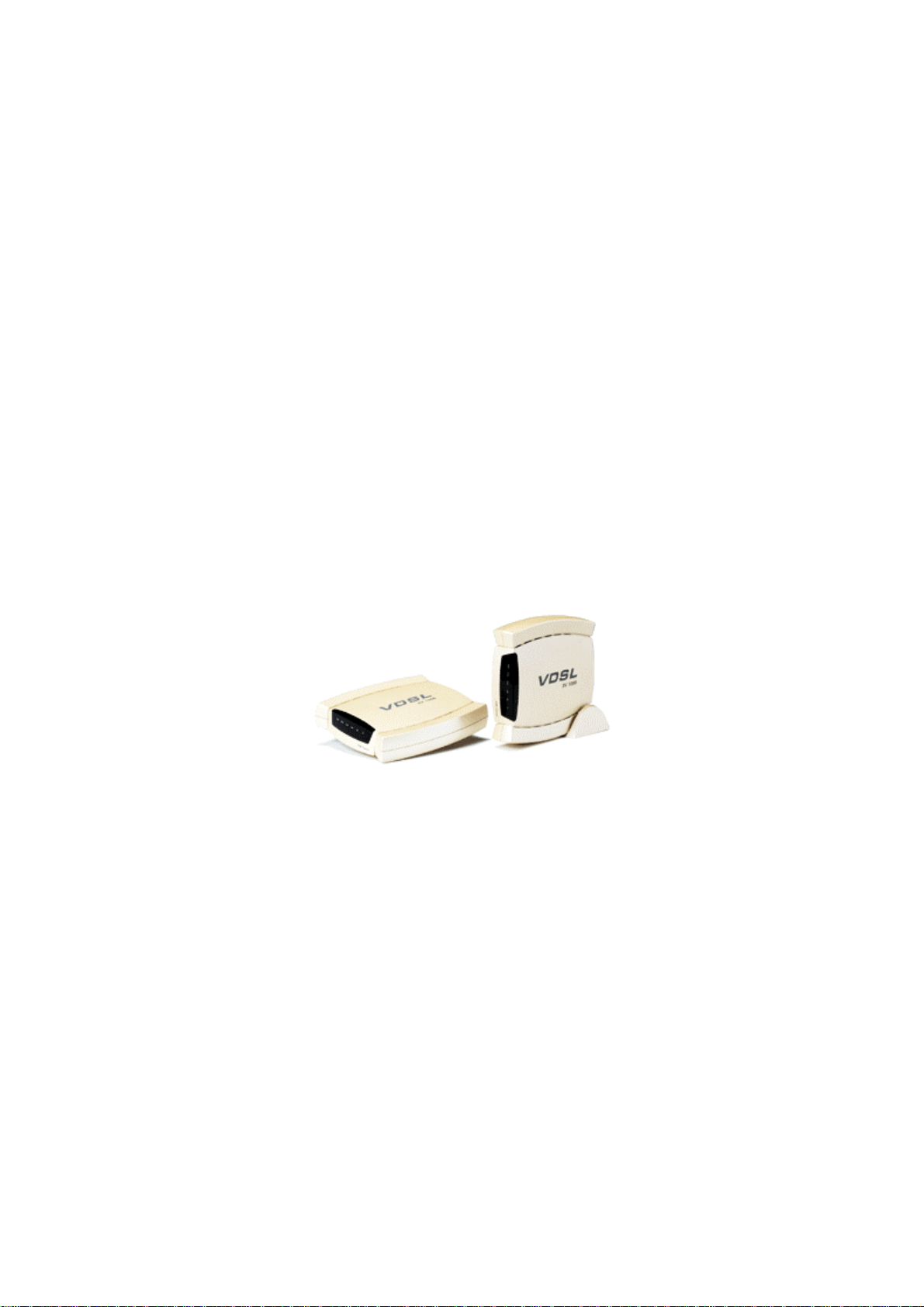
Front
XV1000 VDSL Modem Front Panel
XV 1000
PWR SYNC CHK LINK
LEDs of XV1000 VDSL Modem
Indication Color Function
PWR green lit while AC input power is normal.
SYNC green lit while connected to the VDSLAM
CHK red flashes when error occurs in data communication with
VDSLAM
LINK green lit while connected to the PC
RD green flashes while data is received from the PC
TD green flashes while data is received from the VDSLAM
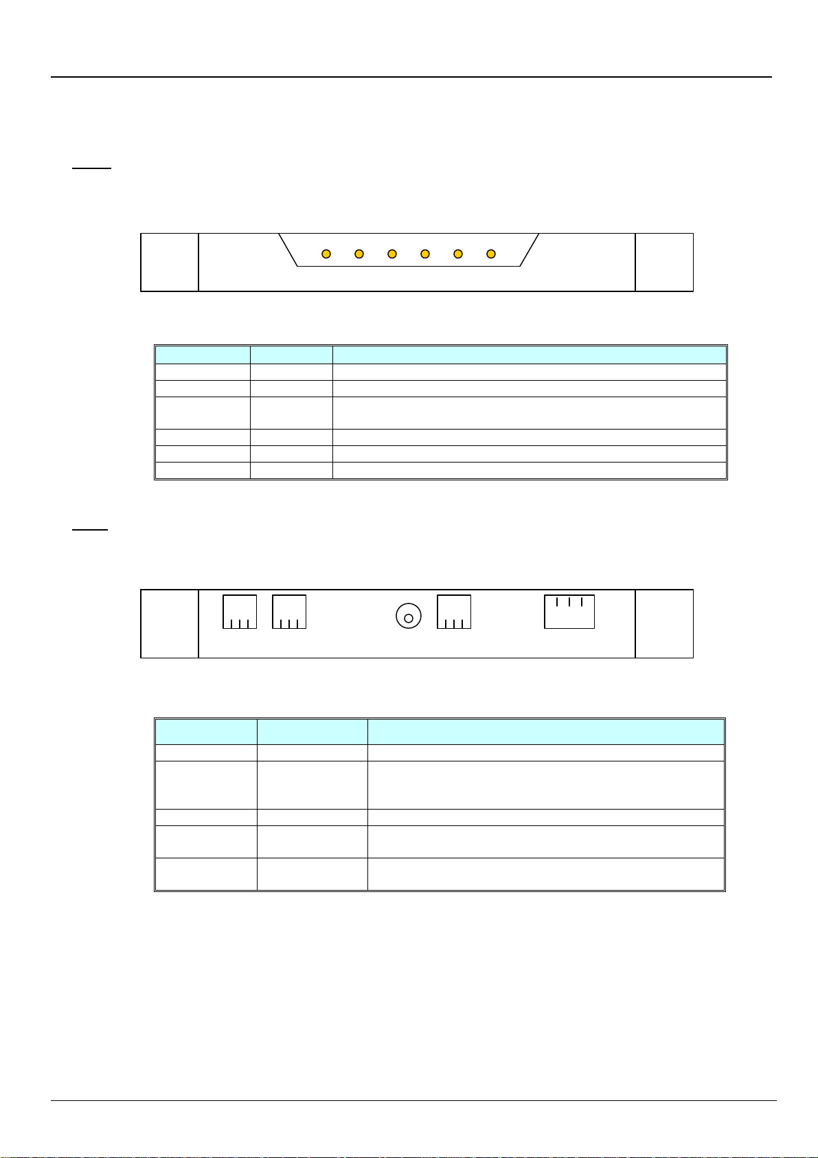
Rear
XV1000 VDSL Modem Real Panel
TEL LINE DC 5V MON 10/100Base-T
Function of XV1000 VDSL Modem Port
Indication Port Function
TEL Telephone Telephone is connected.
LINE VDSL line RJ-11 cable is used to connect the modem to the
telephone socket on the wall.
VDSL data is received/transmitted over this port.
DC 5V Power input Power adaptor (AC 110V/220V, DC/5V) is connected.
MON Serial
(RS232C)
10/100Base-T Ethernet PC LAN card is connected using UTP Category-3,4,5
2
This port is used by the service personnel for the
maintenance of the modem.
Straight-through cable. 10/100Mbps speed is supported.
 Loading...