

Page 1

EZ-Build® Universal Wire
Antenna Hardware Kits
DXE-UWA-KIT
DXE-UWA8X-KIT
DXE-UWA213-KIT
DXE-UWA-KIT-INS Rev 6
No Soldering
DXE-UWA-KIT DXE-UWA8X-KIT
Shown with optional parts Shown with optional parts
© DX Engineering 2020
1200 Southeast Ave. - Tallmadge, OH 44278 USA
Phone: (800) 777-0703 ∙ Tech Support and International: (330) 572-3200
Fax: (330) 572-3279 ∙ E-mail: DXEngineering@DXEngineering.com
Required
- 1 -
Page 2

Introduction
EZ-BUILD® Universal Wire Antenna Kits offer an easy, high quality route to building your own
design wire antennas.
The kits are lightweight yet rugged in design that will allow construction of single band resonant
dipoles, folded dipoles or any center or off-center fed wire antenna you select. If fed with ladder
line, it is usable with a tuner for multi-band operation on all the HF bands. It’s ideal for portable or
tactical use, and permits you to build antennas which can be easily installed in attics, small lots or
Covenant Condition Restricted (CCR) locations.
The Universal Wire Antenna Center Support and End Insulators are made of light weight, high
strength UV-protected material. The Center-T is designed to serve as a feedpoint and strain relief
for antennas made with either wire or ladder line, which may be fed with either ladder line or
coaxial cable. They feature an exclusive serpentine wire grip for insulated DX Engineering Antenna
Wire and high strength, high power 300 Ω Ladder Line. The serpentine connection’s grip is strong
enough to permanently support the antenna wires without the need for looping or wrapping the wire
ends. This allows fast and easy field adjustments of antenna length without soldering. Each kit also
includes crimp-on ring terminals for ladder line and antenna wire and connection hardware. The DX
Engineering DXE-UWA8X and DXE-UWA213 kits include a strain relief bracket and P-Clamps
with neoprene cushions that grip the coaxial cable without deforming it, taking the weight of the
hanging cable off of the connector.
The ladder line feed configuration can be used successfully with the balun incorporated in most
high quality antenna tuners to obtain a low SWR across the entire frequency range. Using a DX
Engineering external current balun may provide better performance and permits converting to
coaxial cable prior to entering the operating position which will reduce RFI. DX Engineering
Baluns, Antenna Wire, 300 Ω Ladder Line and Support Rope are optional items that are available to
make a complete antenna package.
Refer to the end of this assembly manual for information on construction of a few simple dipole
antennas using these kits. For more complete antenna theory and for construction of the many
different types of wire antennas possible with the DX Engineering EZ-BUILD® Universal
Wire Antenna Kits, refer to textbook materials such as the "ARRL Antenna Book" which is also
available from DX Engineering.
Optional Parts Shown
- 2 -
Page 3

You have purchased one of the following DX Engineering Universal Wire Antenna Kits:
Qty
Description
1
Center-T
2
End Insulator
2
10-24 x 3/4” Stainless Steel Carriage Bolt
6
#10 Stainless Steel Flat Washer
6
#10 Stainless Steel Split Washer
6
#10 Star Washer
8
10-24 Stainless Steel Hex Nut
4
10-24 x 5/8 “ Stainless Steel Hex Head Bolt
8
Ring Terminal 18-22
2
Ring Terminal 14-16
Qty
Description
1
Cable Strain Relief Bracket
4
#10 Star Washer
2
10-24 Stainless Steel Nyloc Nut
1
10-24 x 1” Hex Head Stainless Steel Bolt
1
10-24 x 5/8” Stainless Steel Carriage Bolt
1
Aluminum Spacer
1
UHF Female to Female Adapter, 1”
2 *
Cushioned Loop P-Clamp 1 Large, 1 Small
1 **
Pigtail with Ring Terminals installed
DXE-UWA-KIT: EZ-BUILD® Center-T and End Insulators and hardware for wire and
ladder line antennas or for feedpoint-mounted DX Engineering Baluns.
DXE-UWA8X-KIT: EZ-BUILD® Center-T and End Insulators, Medium/Low Power
connector assembly with SO-239 for PL-259 feedline, plus coaxial cable strain relief bracket,
clamps and hardware. The DXE-UWA8X-KIT will handle low and medium power levels
and tolerate medium SWR levels.
DXE-UWA213-KIT: This is a special high power model of DX Engineering’s EZ-BUILD®
versatile insulator kit for building a wire antenna of almost any design. It includes a
completely unique coaxial cable connector and feedline strain relief system. When using a
high power amplifier or high duty cycle modes of operation such as AM, RTTY or FM, this
kit should be used. It will handle higher power levels and tolerate higher SWR levels than
the DXE-UWA8X-KIT.
* P-Clamp size is smaller for the 8X-KIT than the 213-KIT
** The pigtail for the DXE-UWA8X-KIT uses RG-8X coaxial cable
The pigtail for the DXE-UWA213-KIT uses RG-213 coaxial cable
Tools Required
3/8” Wrench, Pliers, 3/8” Socket and Drive or 3/8” Nut Driver, and Wire Stripper
11/32" Wrench and Phillips Head Screwdriver - Used for mounting a balun to the Center-T
Plus all the parts listed in the DXE-UWA-KIT
- 3 -
Page 4
Note: JTL-12555 Jet-Lube SS-30 Anti-Seize is recommended to be used on all clamps, bolts and
stainless steel threaded hardware to prevent galling and to ensure proper tightening.
Basic Assembly
Assembling the Center-T Support
This initial assembly is common to all models.
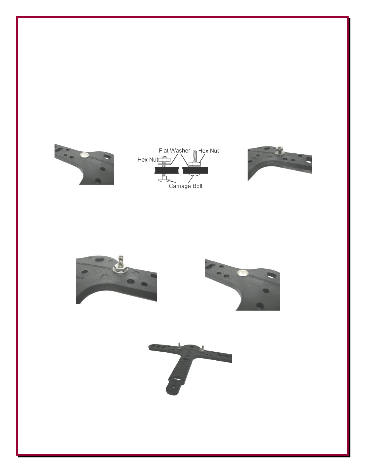
Holding the Center-T, insert a 3/4” Carriage Bolt through the hole shown in Figure 1. The head of
the carriage bolt will be on the same side as the “DXENGINEERING.COM”. This is done so the
element wires (dipole legs) will be routed though the wire restraining holes correctly.
Figure 1 - Carriage Bolt Installation
Holding the carriage bolt in place, turn the Center-T over and install a flat washer, hand tighten the
10-24 hex nut in place. Using a 3/8” wrench tighten the hex nut. As you tighten the nut, the
carriage bolt will draw itself into the support. Tighten the nut until the carriage bolt head is flush to
the support as shown in Figure 2.
Figure 2 -
First Carriage Bolt Flush
Install the second 3/4” carriage bolt, washer and nut using the same sequence as above.
Figure 3 – Second Carriage
Bolt Installed
If you are feeding your antenna with Ladder Line, skip the Coaxial Strain Relief Assembly,
Pigtail Installation, Weatherproofing and P-Clamp Strain Relief instructions and go to page 8.
- 4 -
Page 5

If you purchased the DXE-UWA-KIT and would like to add the coax strain relief, order DXE-
CSR8X-1 for RG-8X, or DXE-CSR213-1 for RG-213 from DX Engineering.
Coaxial Cable Strain Relief Bracket Assembly
Both the DXE-UWA8X-KIT and DXE-UWA213-KIT contain the parts found in the DXE-UWAKIT, (minus the #8 hardware) plus a cable/connector pigtail and cable strain relief. The pigtail for
the 8X-KIT uses RG-8X coaxial cable. The pigtail for the 213-KIT uses RG-213 coaxial cable.
Place the 5/8” carriage bolt through the hole in the bottom of the Center-T assembly as shown in
Figure 4. To fully seat the carriage bolt, use a flat washer and hex nut. Hand tighten the nut in
place and then use a 3/8” wrench tighten the hex nut. As you tighten the nut, the carriage bolt will
draw itself into the support. Tighten the nut until the carriage bolt head is flush to the Center-T.
Remove the nut and washer that were used to fully seat the carriage bolt. Install the star washer
followed by the Cable Strain Relief Bracket, then a Nyloc nut onto the carriage bolt (Figure 5).
Securely tighten the Nyloc nut using a 3/8” wrench or 3/8” nut driver.
Figure 4 - Bottom Hole - Carriage Bolt Installed
Figure 5 - Strain Relief
Bracket Installation
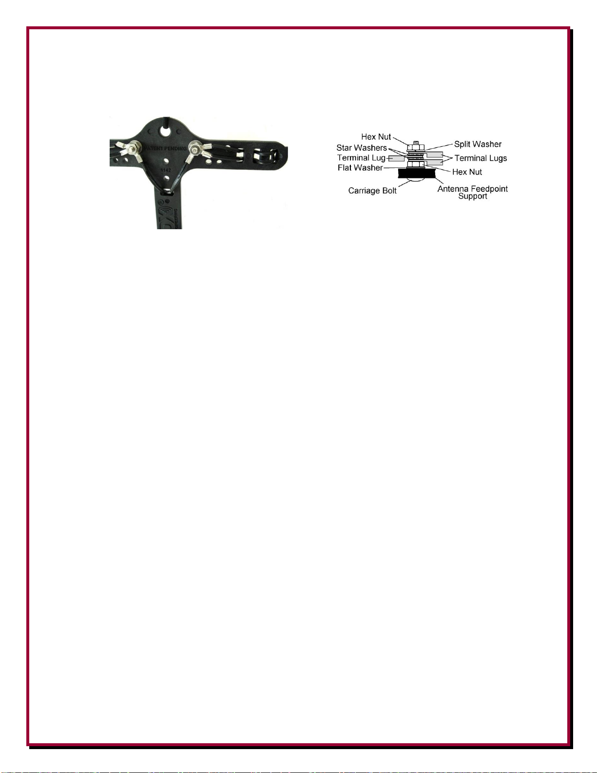
Pigtail Installation
Firmly attach the UHF Female to Female Adapter to the Coaxial Cable Pigtail. Place the pigtail
terminal lugs over the bolts in the Center-T (Figure 6). Use hex nuts to temporarily hold the pigtail
in place on the carriage bolts. Later, when you add the antenna wire, additional hardware will be
added as needed and then tightened.
Figure 6 - Pigtail Installed
- 5 -
Page 6
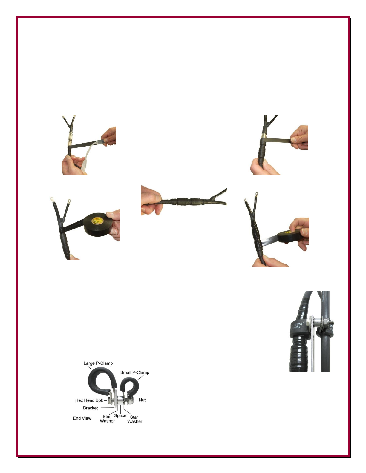
Weatherproofing the Connectors
Firmly attach your coaxial cable to the other end of the UHF Female to Female Adapter. If you
choose to connect your cable after complete assembly, it will be more difficult to wrap the
connectors. The PL-259s & UHF Female to Female Adapter should be weatherproofed using
Temflex Rubber Splicing Tape which is a conformable self-fusing rubber electrical insulating tape.
For outdoor use, the Rubber Splicing Tape should be protected from UV deterioration with an
overwrap of Scotch 33+, a highly conformable super stretchy tape for all weather applications.
Peel back the protective covering.
Tightly wrap the Temflex.
When wrapping, stretch the rubber
splicing tape up to twice its normal length.
Wrap tightly around the coaxial cable and
connectors - overlap each wind of the
tape by about 50%.
Use the Scotch 33+ as an
overwrap to give the assembly
UV protection. Cover the
Temflex Splicing
Tape completely.
P-Clamp Strain Relief Assembly
Loop the cable through the P-clamps and form approximately a 6” diameter loop
of cable. Mount the P-clamps on both sides of the bracket (larger on left, smaller
on right) using the hardware (1” bolt, 1/4” spacer, 3 star washers, and Nyloc nut)
as shown in Figure 7. The larger P-clamp acts as a guide and the smaller Pclamp which is tight around the coaxial cable is the strain relief. Using pliers will
help hold the clamps and parts together while you get the Nyloc nut started.
Figure 7 – P Clamps
- 6 -
Page 7
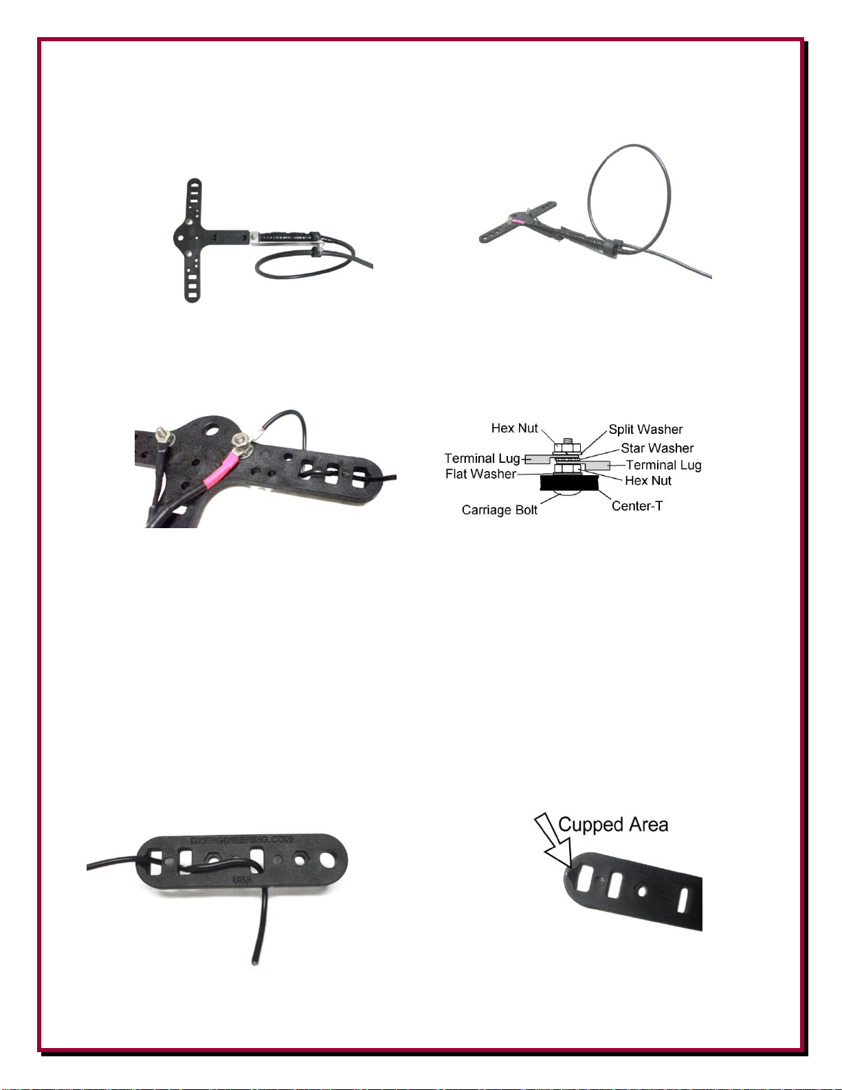
Ensure the coaxial cable going through the P-clamps is properly aligned and has the coaxial cable
loop as shown in Figure 8.
Tighten all the parts holding the P-clamps and coaxial cable in place.
Bottom View Top View
Figure 8 – Center-T with Strain Relief Assembly& Coaxial Cable Attached
Figure 9 – Dipole Wire Leg Installed on Center-T
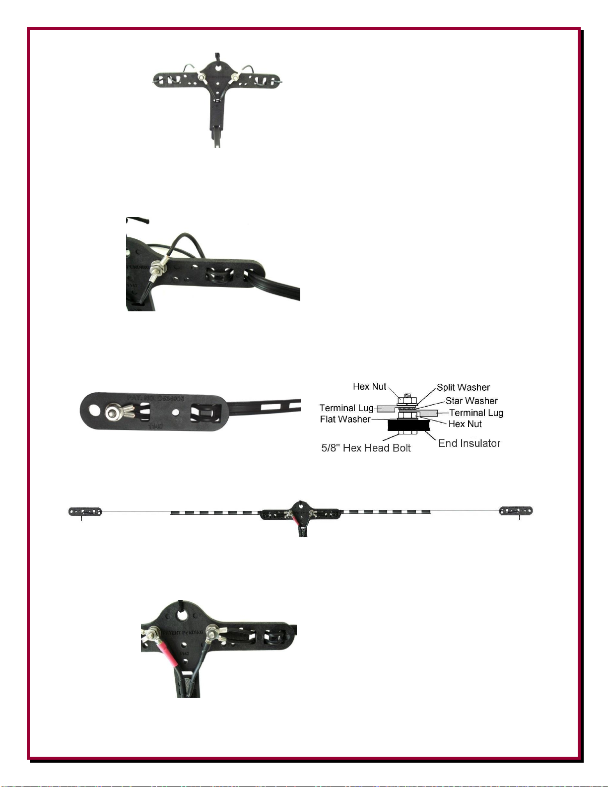
Attaching Dipole Wire to the End Insulators
The end of each dipole leg wire is woven through an end insulator as shown in Figure 10 Note the
way the wire is woven through the End Insulator, especially the side where the antenna wire (dipole
leg) is coming from. There is a dip or cupped out area to assist in a smooth wire transition point.
Both of the dipole leg ends should be measured and cut longer than necessary so final length
adjustments may be made by sliding the wire and then pulling it tight again. Excess can be wrapped
back toward the Center-T. Once tuning is completed at low power, and the dipole leg wires are cut
to the length you want them, the dipole leg wires should look like the bottom picture in Figure 10.
Wrapping and soldering is not required.
Dipole Wire to Center-T
Figure 10 - Dipole Wire & End Insulator
- 7 -
Page 8

Attaching Rope to the End Insulators
UV protected rope should be secured to the Center-T and/or the End Insulators (depending on your
installation) using a non-slip knot. The rope hole (diameter) on the Center-T is 0.371" and the end
insulators are 0.34". One suggestion for attaching the rope is shown in Figure 11. The ends of the
rope should be cauterized with a small flame to prevent the rope braid from fraying.
Figure 11 – Non-Slip Knot using UV protected Rope
Ladder Line Fed Antennas
Attaching the Ladder Line Feedline to the Center-T
The Ladder Line Feedline is woven through the two slots on the Center-T. Once inserted, strip the
ends of the wires to allow installation of the Ring Terminals and attach to the Center-T bolts as
shown in Figure 12.
Figure 12 – Ladder Line Attached to the Center-T
Attaching the Dipole Wire Legs to the Center-T
Strip the center ends of your antenna wires, and crimp the Ring Terminals to each. The ring
terminals may be soldered for longer lasting electrical connection, but soldering is not required for
normal operations. This center end of your dipole wire is then woven through the three slots on the
Center-T. The three slots are designed to grip the DX Engineering DXE-ANTW antenna wire
firmly when pulled tight. There is a small cupped out area in the first (outside) slot that allows a
smooth transition for the wire as it enters the Center-T (Figure 13). Once inserted, attach the ring
terminals to the Center-T bolts as shown in Figure 12 leaving a bit of slack for strain relief. Once
all the terminals and hardware are installed, firmly tighten using the 3/8" wrench or nut driver.
Figure 13 – Cupped Area on Center-T for Dipole Wire Leg
- 8 -
Page 9

Antenna Installation
Safety Considerations
WARNING!
INSTALLATION OF ANY ANTENNA NEAR POWER LINES IS DANGEROUS
Warning: Do not locate the antenna near overhead power lines or other electric light or power
circuits, or where it can come into contact with such circuits. When installing the antenna, take
extreme care not to come into contact with such circuits, because they may cause serious injury or
death.
Overhead Power Line Safety
Before you begin working, check carefully for overhead power lines in the area you will be
working. Don't assume that wires are telephone or cable lines: check with your electric utility
for advice.
Although overhead power lines may appear to be insulated, often these coverings are intended only
to protect metal wires from weather conditions and may not protect you from electric shock
Keep your distance! Remember the 10-foot rule: When carrying and using ladders and other long
tools, keep them at least 10 feet away from all overhead lines - including any lines from the power
pole to your home.
Mounting Considerations
When planning the location of your antenna, consideration should be given to the height, location of
suitable support structures and feedline positioning and length.
Generally speaking, dipole antennas should be mounted as high as possible for best performance.
Antenna height will affect the exact resonance point, radiation pattern, and takeoff angle. The
higher the antenna, the lower the takeoff angle to the horizon, which increases the effective range of
the antenna.
For DX, the minimum height above ground should be 1/2 to 1-wavelength at the lowest operating
frequency. On the low bands, this height becomes impractical for most hams. For example, an 80m
dipole at 70 feet is about 1/4-wavelength above the ground. This antenna would be good for local
and short distance communications, but not optimal for DX, due to the high takeoff angle and
ground absorption. A 40 Meter dipole at 70 feet is approximately 1/2-wavelength high and is likely
to be good for DX and less optimal for local or short range communications. For more information
- 9 -
Page 10

on antenna design, feedline and radiation angles, consult a reliable text such as the "ARRL Antenna
Book" which is available from DX Engineering.
Support Line
The Center-T’s top hole is used for the attachment of a UV protected messenger rope line that is
used to provide support for the antenna wire and feedline. The use of the messenger line, which is
strongly recommended when a DX Engineering balun is attached, will reduce the stress on the
element wires and keep the antenna from stretching over time, which will change its resonant
frequency.
When using trees for support, you may want to use counter weights that will allow the rope to move
when the trees sway in the breeze to avoid stretching or breaking your dipole. For more hints,
consult a reliable text such as the "ARRL Antenna Book" which is available from DX Engineering.
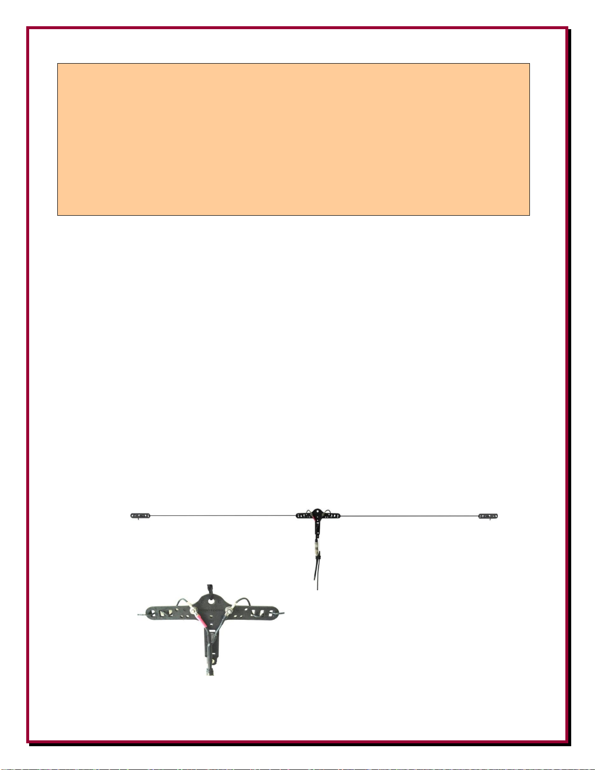
Ideally, the messenger line should attach to the same structure used for the dipole, only above it,
forming at least a 30 degree angle between the dipole and the messenger line to support the antenna.
See Figure 14.
Figure 14 – Flat Dipole Installation using a Messenger Line
UV protected rope is used for the messenger line by forming a loop at the mid-point of the rope.
Push the loop through the Center-T top hole, and pull the rest of the rope through the loop. See
Figure 15.
Figure 15 – UV protected Rope Loop for Messenger Line
The excess rope can be used to attach the antenna end insulators to the support structures. Use the
same structures used by the messenger line if possible. The ends of the rope should be cauterized
with a small flame to prevent the rope braid from fraying.
- 10 -
Page 11
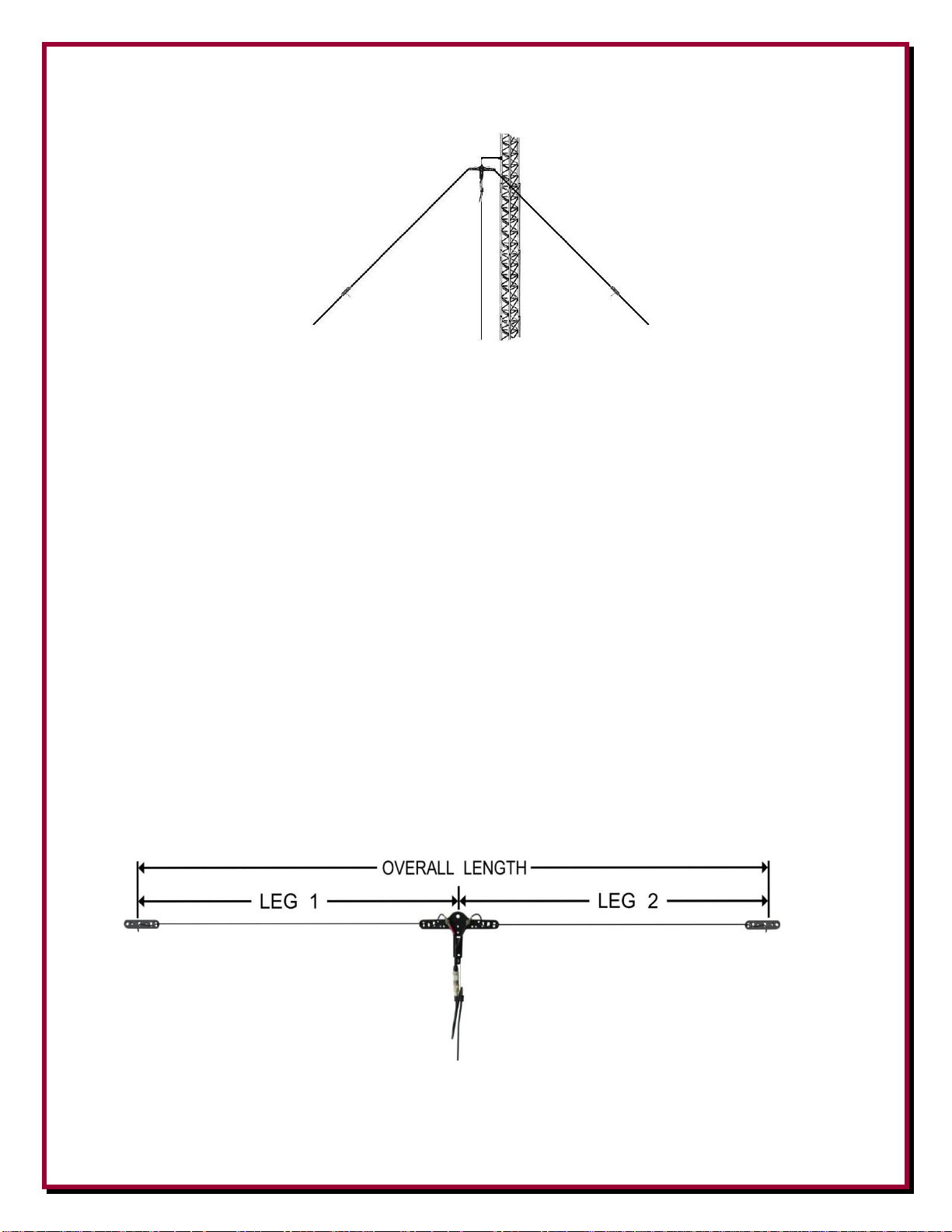
The top support hole may also be used for rope to install it as an inverted-V (Figure 16).
Figure 16 – Inverted-V Dipole – Tower Side Arm Installation
Tower side arm Universal Mounting Plates and Saddle Clamps are available from DX Engineering.
Single Band Center Fed Half Wave Dipole
When building a single band coaxial cable fed HF dipole antenna, you may easily use the formula
L = 468/F to determine the overall length of the wire (L in feet, F in MHz). The formula takes into
account the end-effect of the antenna wire to give you the overall length of the wire portion.
As an example, using the formula L = 468/F, the overall length of a halfwave dipole for 3.800 MHz
would be L = 468/3.800 or 123.2 feet. Cut the overall length of the wire to 125 feet or more to
include the extra length for tuning, then cut that in half to provide two dipole legs – each 62.5 feet
long – for attachment to the Center-T and feedline (Figure 17).
Use this theoretical formula length as a starting point to cut the wire, leaving about one foot extra on
each dipole leg for wire fastening and fine tuning adjustment to allow for anomalies and
environmental effects in your particular installation. Longer length dipole legs may be required for
Inverted-V antennas.
DXE-ANTW-(-75 ft., -150 ft., -300 ft., -500 ft., -1000 ft.) #14 Insulated Antenna Wire is specially
manufactured for use with the DXE-UWA kits.
Figure 17 - Example: 3.800 MHz Overall Length cut to 125 Ft.
Leg 1 = 62.5 Ft.
Leg 2 = 62.5 Ft.
Overall length plus some extra for wire fastening & tuning
Longer length dipole legs (up to 2 feet longer) may be required for Inverted-V antennas.
- 11 -
Page 12
If you purchased the DXE-UWA-KIT and would like to add the coax strain relief shown in Figure
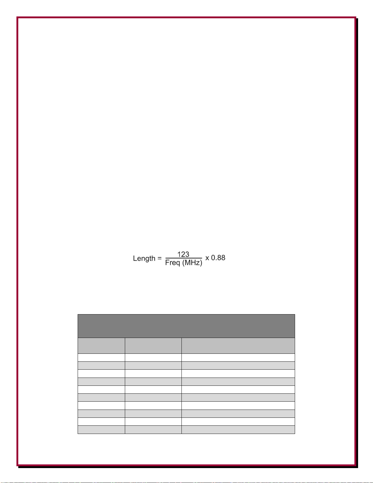
Table 1
Recommended Antenna and Feedline Length for
Shortened Multi-Band Dipoles for easier tuning
Frequency
(MHz)
Shortened
Dipole (Ft.)
Make feedline an Odd Multiple of
this length in Feet (x 1, 3, 5, etc.)
1.8
220
60.1
3.5
110
30.9
5.3
76
20.4
7
55
15.4
10.1
41
10.7
14
29
7.7
18
22
6
21
19
5.2
24
19
4.5
28
19
3.9
17, order DXE-CSR8X-1 for RG-8X, or DXE-CSR213-1 for RG-213 from DX Engineering.
Multi-Band Center Fed Shortened Dipole using Ladder Line Feedline
A simple multi-band dipole may be constructed by first choosing the lowest band on which
operation is desired. The overall length of the dipole antenna should be a shortened half wavelength
as shown in Table 1. This antenna will be fed with ladder line and an antenna tuner with balanced
connections. You can also use a DX Engineering external balun connected with coaxial cable to an
unbalanced tuner for tuning the different bands.
Although it may not seem logical, shortening a multi-band dipole intended for 160 through 10 meter
operation to less than 220 Ft. will actually help your wide range antenna tuner cover the lower
frequencies easier. That is because you are using a non-resonant antenna system when you use
ladder line feed systems for multi-band operations. Changing the length of the ladder line will alter
resulting impedances enough so that the tuner may be able to reach a certain frequency that was
giving it trouble. The coax from a DX Engineering 1:1 Balun to the tuner should be kept short;
typically 5 to 15 feet is best.
The DXE-LL300 - 300 Ω ladder feedline for a multi-band dipole must be in odd multiple lengths of
1/8 wavelength on the lowest operating frequency, used to optimize the impedance presented to the
balun and tuner over the frequency range of the antenna. This length can be calculated using the
following formula or use Table 1. The DX Engineering 300 Ω ladder feedline has a VF (Velocity
Factor) of 0.88.
Formula:
Where: 123 = 1/8-Wavelength Factor, Freq = Frequency in MHz,
0.88 = Velocity Factor of DXE-LL300 300 Ω Ladder Feedline
Multiply the result times the odd multiple (1, 3, 5, 7, etc) to get the correct length closest to your
required feedline length.
Note: If using an external balun, the feedline length should be calculated to the balun.
- 12 -
Page 13
Example: To use an antenna from 80 meters to 10 meters, the feedline should be in odd 1/8
wavelength multiples on 80 meters.
The 80 meter band starts at 3.5 MHz. Therefore, 123/3.5 = 35.1.
DX Engineering feedline has a VF of 0.88, so 35.1 x 0.88 = 30.9 ft. per 1/8-wavelength.
If 90 feet is required to get to your operating position, the nearest odd multiple 1/8 wavelength
length is 92.7 feet (30.9 x 3).
If you needed 110 feet, you would have to add to the feedline to achieve 154.5 feet (30.9 x 5) to
maintain the odd 1/8th multiple rule for length.
If you need to splice ladder line together for longer lengths, use the DXE-LLC-1P Ladder Line
Coupler.
If you have excess ladder line, it can be zigzagged while suspended in air, but it can't be closer than
a few conductor widths to metallic objects and cannot be coiled or laid on the ground. If it is
necessary to pass closely to a metallic object, twist the line to partially balance the effect on both
sides of the feedline.
Sample Dipole Configurations
Using the EZ-Build® Universal Wire Antenna Hardware Kits will allow you to build many
types of wire and ladder line antenna configurations. Consult a reliable text such as the "ARRL
Antenna Book" which is available from DX Engineering for other types of wire antennas (Off
Center Fed, Loop and many more).
Attachment of other wire type antennas to the EZ-BUILD® Universal Wire Antenna Kit is
basically the same as described. The following pictures show some typical applications.
Single Wire Element
Typical Single Band Dipole (not to scale)
DX Engineering Coaxial Stub & Strain Relief
DX Engineering UV Resistant Antenna Wire
Coaxial Feed
UV Resistant Support Rope
- 13 -
Page 14
Ladder Line Feed
DX Engineering UV Resistant Antenna Wire
DX Engineering 300-ohm Transmitting Twinlead
UV Resistant Support Rope
Folded Dipole Element
Ladder Line Feed
DX Engineering 300-ohm Transmitting Twinlead
UV Resistant Support Rope
Suggested method to secure the ladder line for a Folded Dipole Element on the end insulators:
Dual Frequency Element
Typical Dual Band Dipole using Ladder Line. Upper dipole leg wire is cut for lower frequency,
lower dipole leg is cut wire for higher frequency (not to scale).
Coaxial Feed
DX Engineering UWA Kit with Strain Relief
DX Engineering 300-ohm Transmitting Twinlead
UV Resistant Support Rope
- 14 -
Page 15
Ladder Line Feed
DX Engineering UWA Kit with
DX Engineering 300-ohm Transmitting Twinlead
UV Resistant Support Rope
NOTES:
- 15 -
Page 16

Manual Updates
Every effort is made to supply the latest manual revision with each product. Occasionally a manual
will be updated between the time your DX Engineering product is shipped and when you receive it.
Please check the DX Engineering web site (www.dxengineering.com) for the latest revision manual.
Technical Support
If you have questions about this product, or if you experience difficulties during the installation,
contact DX Engineering at (330) 572-3200. You can also e-mail us at:
dxengineering@dxengineering.com
For best service, please take a few minutes to review this manual before you call.
Warranty
All products manufactured by DX Engineering are warranted to be free from defects in material and workmanship for a
period of one (1) year from date of shipment. DX Engineering’s sole obligation under these warranties shall be to issue
credit, repair or replace any item or part thereof which is proved to be other than as warranted; no allowance shall be
made for any labor charges of Buyer for replacement of parts, adjustment or repairs, or any other work, unless such
charges are authorized in advance by DX Engineering. If DX Engineering’s products are claimed to be defective in
material or workmanship, DX Engineering shall, upon prompt notice thereof, issue shipping instructions for return to
DX Engineering (transportation-charges prepaid by Buyer). Every such claim for breach of these warranties shall be
deemed to be waived by Buyer unless made in writing. The above warranties shall not extend to any products or parts
thereof which have been subjected to any misuse or neglect, damaged by accident, rendered defective by reason of
improper installation, damaged from severe weather including floods, or abnormal environmental conditions such as
prolonged exposure to corrosives or power surges, or by the performance of repairs or alterations outside of our plant,
and shall not apply to any goods or parts thereof furnished by Buyer or acquired from others at Buyer’s specifications.
In addition, DX Engineering’s warranties do not extend to other equipment and parts manufactured by others except to
the extent of the original manufacturer’s warranty to DX Engineering. The obligations under the foregoing warranties
are limited to the precise terms thereof. These warranties provide exclusive remedies, expressly in lieu of all other
remedies including claims for special or consequential damages. SELLER NEITHER MAKES NOR ASSUMES ANY
OTHER WARRANTY WHATSOEVER, WHETHER EXPRESS, STATUTORY, OR IMPLIED, INCLUDING
WARRANTIES OF MERCHANTABILITY AND FITNESS, AND NO PERSON IS AUTHORIZED TO ASSUME
FOR DX ENGINEERING ANY OBLIGATION OR LIABILITY NOT STRICTLY IN ACCORDANCE WITH THE
FOREGOING.
©DX Engineering 2020
DX Engineering®, DXE®, DX Engineering, Inc.®, Hot Rodz®, Maxi-Core®, DX Engineering THUNDERBOLT®,
DX Engineering Yagi Mechanical®, EZ-BUILD®, TELREX®, Gorilla Grip® Stainless Steel Boom Clamps,
Butternut®, SkyHawk™, SkyLark™, SecureMount™, OMNI-TILT™, RF-PRO-1B®, AFHD-4® are trademarks of
PDS Electronics, Inc. No license to use or reproduce any of these trademarks or other trademarks is given or implied.
All other brands and product names are the trademarks of their respective owners.
Specifications subject to change without notice.
- 16 -
 Loading...