

Page 1

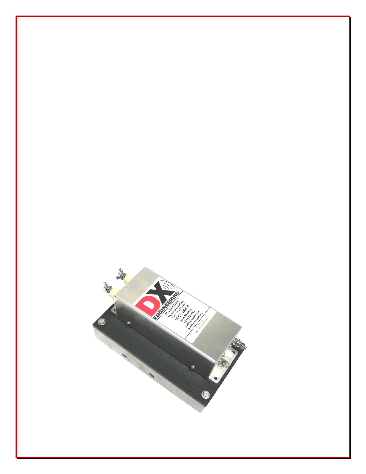
Vertical Feedline Current Choke Kit
DXE-VFCC-H05-A
DXE-VFCC-H10-A
DXE-VFCC-H05-H10A-INS-Rev 6d
DX Engineering 2012
P.O. Box 1491 ∙ Akron, OH 44309-1491 USA
Phone: (800) 777-0703 ∙ Tech Support and International: (330) 572-3200
Fax: (330) 572-3279 ∙ E-mail: DXEngineering@DXEngineering.com
- 1 -
Page 2

Introduction
The DXE-VFCC Vertical Feedline Current Choke kits are designed for use with coaxially fed, 50 Ω vertical
antennas such as the Hustler® BTV series, the DX Engineering family of verticals and many others.
The advantages of using a VFCC:
Offers a substantially greater amount of isolation and current balance than coiled coaxial cable
All power goes to the antenna system improving efficiency
Prevents unwanted RFI by eliminating feedline current and radiation
Reduces noise or unwanted signals picked up by the feedline
Overcomes a less than optimal ground system
When quarter-wave vertical antennas are constructed over a good radial system, they have a feedpoint
impedance of about 36 Ω. When they are installed over an inadequate ground radial system there is a loss
introduced at the feed point that adds to the 36 Ω figure. This apparently improves the SWR but there is a
loss in the efficiency of the antenna. Transmitted and received signals suffer attenuation from this
inefficiency. Often, currents introduced on the feedline shield will cause unwanted transmit RFI and received
noise.
With a ground-mounted quarter-wave vertical, regardless of the radial situation, but especially with poor
radial systems, there is the need for a DXE-VFCC-H05-A Vertical Feedline Current Choke (VFCC) to keep
current off the feedline.
The VFCC kit comes in two power levels. The DXE-VFCC-H05-A rated at 2 kW continuous and the DXE-
VFCC-H10-A, rated at 5 kW continuous. Both kits include an insulated mounting plate used to mount the
choke to the base of the vertical and the necessary braid used to connect the choke to the vertical feed point
and ground system.
When a 1/4-wavelength vertical is mounted well above the ground and uses elevated radials, it is difficult to
keep current from traveling back to the operating position via the feedline. In this application, using an
additional feedline current choke like the DX Engineering DXE-FCC050-H05-A installed outside of the
near field of the vertical will further reduce feedline currents.
Additional Items Required
Mounting Clamp - Stainless Steel V-Clamp DXE-SSVC-2P, to mount the insulated plate to a 1" to 2" OD
(maximum) ground mounting pipe, usually the same one used to mount the vertical antenna.
Installation
Ground Mounted Vertical Antenna
The VFCC kit should be mounted to the same mounting pipe used to mount the vertical antenna. The
standard 1-1/2" galvanized water pipe (with its 1.9" OD) is just fine for this application and can
usually be found at your local home building supply store. It should be mounted horizontally as close to
the base of the vertical antenna as possible. If you are using a DX Engineering Tilt Base, sufficient clearance
is needed to ensure the antenna does not contact the VFCC when tilted. Proper orientation of the VFCC to
the Tilt Base also ensures good geometry of the feed connections during tilting.
- 2 -
Page 3

When using the DXE-RADP-3 Radial Plate, the VFCC shelf bracket should mounted so there is
approximately 1/8" to 1/4" gap between the insulated shelf bracket and the Radial Plate mounting tab. The
VFCC requires approximately 7” clearance from the radial plate to the bottom of the tilt-base to allow the
tilt-base to operate with no interference. Your set up may vary and dimensions may be adjusted. Use Figures
2 and 3 for orientation.
Mount the VFCC and the Mounting Bracket to the Insulated Shelf as shown in Figure 1.
Figure 1
Figure 2
After mounting the VFCC as shown in Figures 2 and 3, connect the 8.5"
braid to the bottom of the vertical antenna. Make sure you are using the
terminal closest to the Red "D" in DX ENGINEERING on the VFCC
label. Route the braid as shown in Figure 2.
Connect the 7.5" braid from the other VFCC terminal to the closest radial
wire bolt on the radial plate or ground system.
When making connections to the terminals, the braid should be placed
between the flat washers. The wing nuts should be hand tightened
only. Do not use pliers or other tools to tighten them as excessive force
may damage the internal connections or the ceramic insulators.
- 3 -
Page 4

The use of a 3/8" open end wrench is strongly suggested to hold the hex nut in place while you hand tighten
the wing nut. This will prevent the 2-1/2" long hex bolt that goes inside the balun from rotating and possibly
breaking an internal soldered connection.
The supplied wing nuts should be hand tightened only. Do not use pliers or other tools to tighten them as
excessive force may damage the internal connections or the ceramic insulators.
Example shown:
Connection of Braided Feedline
and Hand Tightening the Wing Nuts
The DX Engineering VFCC is not affected by moisture and may be left outside in all types of weather,
including heavy rain, as long as the VFCC is positioned so that water will drain from the case. However, they
may not be immersed in water and care should be taken to avoid blocking the drainage of condensation or
any water that could get inside.
To enhance weather resistance, it may be useful to put a bead of high quality, non corrosive, marine grade
silicone, like DX Engineering part number UMI-82180, along the seams. Depending on the mounting
orientation, leave a small opening in the seam at the lowest point to allow any condensation to drain. Silicone
which contains acetic acid, which has a vinegar-like smell, is corrosive to aluminum and should be avoided.
We recommend the use of a high quality DXE-PL259 Teflon® silver PL-259 connector. Be sure to
waterproof the coax connection with proper tape layers, first using DXE-3M2155 rubber splicing tape. Wrap
the connector with one layer from end-to-end while stretching the tape by a factor of about 2:1. Follow with
a wrap of TRM-06132 vinyl tape. Unlike some waterproofing solutions promoted to the Amateur market,
splicing tape can be easily removed at any time and will not permanently adhere to the fitting.
DX Engineering VFCC units require no maintenance when properly installed.
There is a spare wing nut with hardware next to the SO-239. Your existing coaxial cable from your radio
connects directly to the SO-239 on the VFCC. DO NOT ground the case of the VFCC.
- 4 -
Page 5

Figure 3 - Typical Installation with a Hustler BTV, optional DXE-TB-3P Tilt Base,
DXE-RADP-3 Radial Plate and DXE-SSVC-2P V-Clamps
The orientation of the VFCC, Tilt Base and Radial Plate must be as shown to ensure correct operation of the
tilt base with the VFCC. The braid must not touch the VFCC case. If necessary, loosen the VFCC braid
connection to the feed point to prevent excessive strain on the braid when tilting.
For various reasons, Hustler or other 1/4-wavelength vertical antennas are installed with no radials or with an
inadequate number of radials. This is not recommended, but it happens. As a result, the antenna uses the
coax as a radial and by doing so, introduces common-mode current on the braid of the feedline, which can
travel to the operating position resulting in RFI and unwanted signal ingress.
In order to reduce the unwanted current on the feedline shield in these situations, the DX Engineering VFCC
will make the best of a non-optimal installation. With no ground system, attach the terminal of the VFCC
that would normally go to the Radial Plate to the frame of the antenna support bracket or mounting pipe
where the radial wires would normally be attached as indicated in the manual.
Your coaxial cable from your radio connects directly to the SO-239 connector on the VFCC. Do not connect
your coaxial cable through a bulkhead connector on the Radial Plate
- 5 -
Page 6
Elevated-Mount Verticals
For verticals that are mounted well off the ground, usually on a roof or small tower, the radial system must
also be elevated. In these cases, mount the VFCC on the mounting mast UNDER the radials close to the feed
point of the raised vertical. The radial wires should extend away from the vertical at a 30 to 60 degree down
angle and should not touch the VFCC. Attach the terminal of the VFCC that would normally go to the Radial
Plate to same mounting point where the radial wires are attached. Sometimes, as the coax feedline travels
through the near field of the antenna, the current can be re-introduced onto the feedline. In that case, a DX
Engineering DXE-FCC050-H05-A Feedline Current Choke should be inserted into the feedline after it exits
the near field of the antenna or at the station end of the feedline.
Other Applications
When using the DXE-VFCC in other applications such as an Inverted-L antenna, connect the terminal
nearest the Red "D" in DX ENGINEERING on the VFCC label to the feedpoint of the vertical antenna.
The terminal nearest the Black "X" in DX ENGINEERING on the label connects to the ground radial
system.
Your existing coaxial cable from your radio connects directly to the SO-239 on the VFCC. There is a spare
wing nut with hardware next to the SO-239.
DO NOT ground the case of the VFCC .
- 6 -
Page 7

Optional Items
*UMI-81343
Anti-Seize, 1 oz. Squeeze Tube
*UMI-81464
Anti-Seize, 8.5 oz. Aerosol Can
*DXE-NSBT8
Never-Seez®, 8 oz. Brush Top
*DXE-NMBT8
Never-Seez®, 8 oz. Brush Top, Marine Grade
UMI-81343, UMI-81464, DXE-NSBT8, DXE-NMBT8 - Never-Seez® & Anti-Seize
An Anti-seize compound MUST be used on any Stainless Steel nuts, bolts, clamps or other hardware to prevent galling
and thread seizure. Any of these products can be used for this purpose.
* These products are limited to domestic UPS Ground shipping only
DXE-SSVC-2P - Stainless Steel V-Clamp for steel pipe, 2 inch V-bolt
This V-Clamp is made in one size that fits Steel tubing or pipe from 1" to 2'' OD as used in antenna construction. The
supplied V-bolt is long enough to attach tubing to thick plates and is made with anti-corrosive properties. The special
Stainless Steel saddle has serrated teeth will clamp to the pipe securely by biting into the surface. For this reason, it is not
recommended for softer aluminum tubing or pipe. Ideal for fastening a radial plate and antenna mounting to a steel pipe.
Used to clamp 1 to 2'' (OD) steel tubing or pipe
Designed for attachments that don't require resistance to torque
V-bolt and saddle made from high-strength 18-8* stainless steel
* The use of an anti-seize compound is HIGHLY recommended to achieve proper torque and prevent galling.
DXE-RADP-3 - Radial Plate, Stainless Steel w/ 20 Sets of SS Radial Attachment Hardware
The DX Engineering Radial Plate is meant for those of you that have or are building a quarter wave vertical
antenna and who want an easy, neat and effective way to connect those essential radial wires and the coax to your
vertical antenna for the lowest takeoff angle and strongest signals. DX Engineering Radial Plate is laser cut from
tough stainless steel so that it has smooth edges, won’t corrode and will always look good. You will be proud of
how good your installation looks. This plate will work perfectly with most commercially available vertical
antennas such as the Hustler® BTV series (4-BTV thru the 6-BTV), the SteppIR™ (BiggIR or SmallIR) or one of
your own construction
DXE-3M2155 - 3M Temflex™ 2155 Rubber Splicing Tape.
Conformable self-fusing rubber electrical insulating tape. It is designed for low voltage electrical insulating and moisture
sealing applications. For outdoor use, it should be protected from UV deterioration with an overwrap of TRM-06132
TRM-06132 - Scotch® Super 33+.
Highly conformable super stretchy tape for all weather applications. This tape provides flexibility and easy handling for
all around performance. It also combines PVC backing with excellent electrical insulating properties to provide primary
electrical insulation for splices up to 600V and protective jacketing. Both tape products are available from DX
Engineering.
UMI-82180 - Permatex Black RTV Sealant, Non-Acetic - 3.3 oz. Tube, Black DX Engineering Approved RTV
Sealant By Permatex®
We have all used RTV to seal water out of things, right? Have you ever sealed a piece of electronic gear with it -- then
opened it some time later to find that it had still managed to become corroded inside? Guess what? It's not the rain that
corroded it - It's the RTV! Normal RTV gives off acetic acid when it cures. That's the vinegar smell. The acetic acid
causes the corrosion.
DX Engineering has located a Neutral Cure RTV made right here in Ohio that is non-corrosive and is safe for sealing those
baluns and other electronic gear that are going to be out in the weather.
Applies just like "normal" RTV, dries in one hour and cures in 24 hours at 70 degrees F. And it doesn't smell like vinegar!
3.3 oz. Tube
Black
*This part is classified hazardous and is limited to domestic UPS Ground shipping only
- 7 -
Page 8

Technical Support
If you have questions about this product, or if you experience difficulties during the installation, contact DX
Engineering at (330) 572-3200. You can also e-mail us at:
dxengineering@dxengineering.com
For best service, please take a few minutes to review this manual before you call.
Manual Updates
Every effort is made to supply the latest manual revision with each product. Occasionally a manual will be updated
between the time your DX Engineering product is shipped and when you receive it. Please check the DX Engineering
web site (www.dxengineering.com) for the latest revision manual.
Warranty
All products manufactured by DX Engineering are warranted to be free from defects in material and workmanship for a
period of one (1) year from date of shipment. DX Engineering’s sole obligation under these warranties shall be to issue
credit, repair or replace any item or part thereof which is proved to be other than as warranted; no allowance shall be
made for any labor charges of Buyer for replacement of parts, adjustment or repairs, or any other work, unless such
charges are authorized in advance by DX Engineering. If DX Engineering’s products are claimed to be defective in
material or workmanship, DX Engineering shall, upon prompt notice thereof, issue shipping instructions for return to
DX Engineering (transportation-charges prepaid by Buyer). Every such claim for breach of these warranties shall be
deemed to be waived by Buyer unless made in writing. The above warranties shall not extend to any products or parts
thereof which have been subjected to any misuse or neglect, damaged by accident, rendered defective by reason of
improper installation, damaged from severe weather including floods, or abnormal environmental conditions such as
prolonged exposure to corrosives or power surges, or by the performance of repairs or alterations outside of our plant,
and shall not apply to any goods or parts thereof furnished by Buyer or acquired from others at Buyer’s specifications.
In addition, DX Engineering’s warranties do not extend to other equipment and parts man ufactured by others except to
the extent of the original manufacturer’s warranty to DX Engineering. The obligations under the foregoing warranties
are limited to the precise terms thereof. These warranties provide exclusive remedies, expressly in lieu of all other
remedies including claims for special or consequential damages. SELLER NEITHER MAKES NOR ASSUMES ANY
OTHER WARRANTY WHATSOEVER, WHETHER EXPRESS, STATUTORY, OR IMPLIED, INCLUDING
WARRANTIES OF MERCHANTABILITY AND FITNESS, AND NO PERSON IS AUTHORIZED TO ASSUME
FOR DX ENGINEERING ANY OBLIGATION OR LIABILITY NOT STRICTLY IN ACCORDANCE WITH THE
FOREGOING.
©DX Engineering 2012
DX Engineering®, DXE®, DX Engineering, Inc.®, Hot Rodz®, Maxi-Core®, DX Engineering THUNDERBOLT™,
DX Engineering Yagi Mechanical®, EZ-BUILD®, TELREX® and Gorilla Grip® Stainless Steel Boom Clamps, are
trademarks of PDS Electronics, Inc. No license to use or reproduce any of these trademarks or other trademarks is given
or implied. All other brands and product names are the trademarks of their respective owners.
Specifications subject to change without notice.
- 8 -
 Loading...