


- 1 -
Receive Short
Element Active
Vertical Antenna
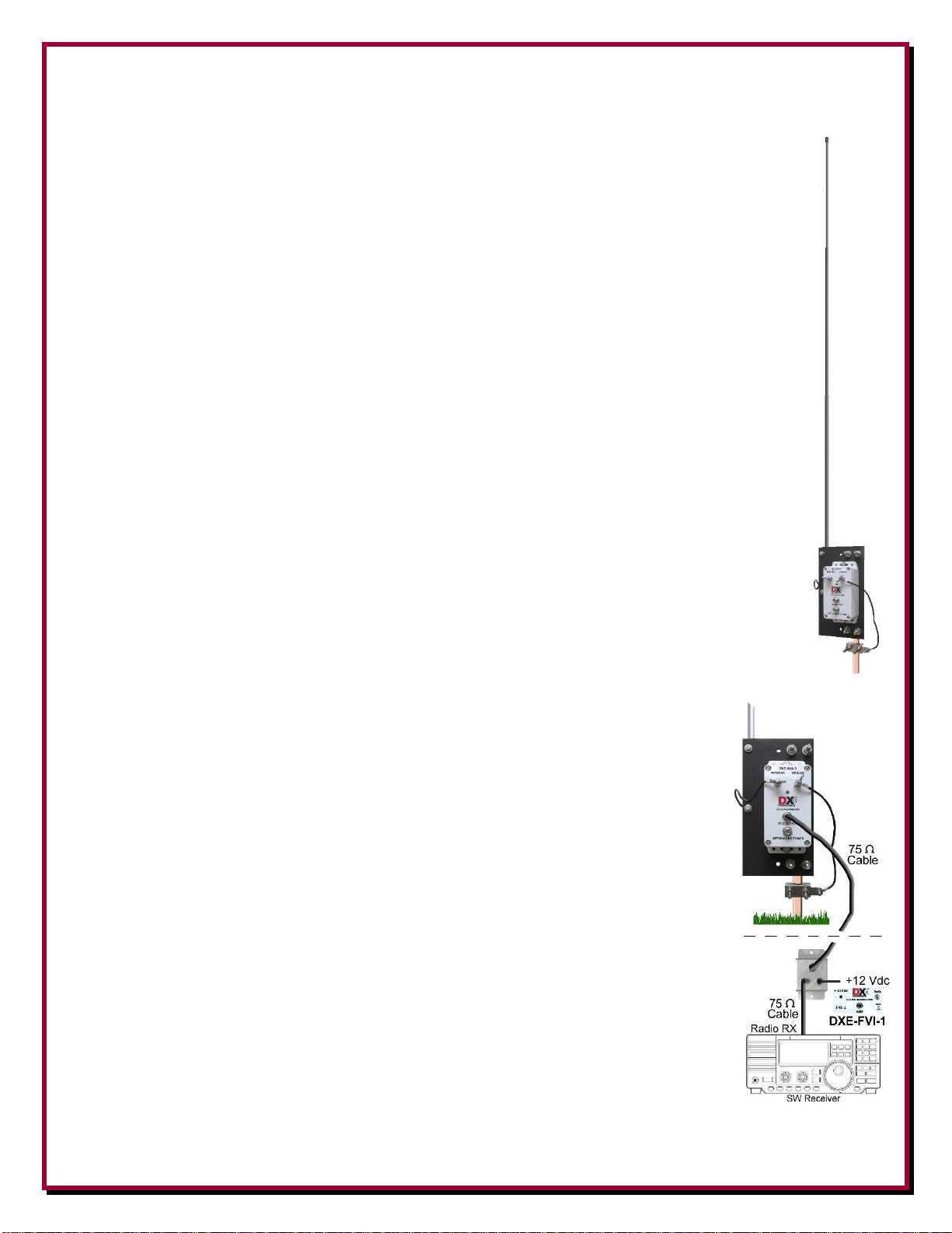
DXE-RSEAV-1 - Single Active Vertical Antenna
DXE-RSEAV-1FVI - Single Active Vertical Antenna
w/Feedline Voltage Inserter
DXE-RSEAV-INS-Revision 0
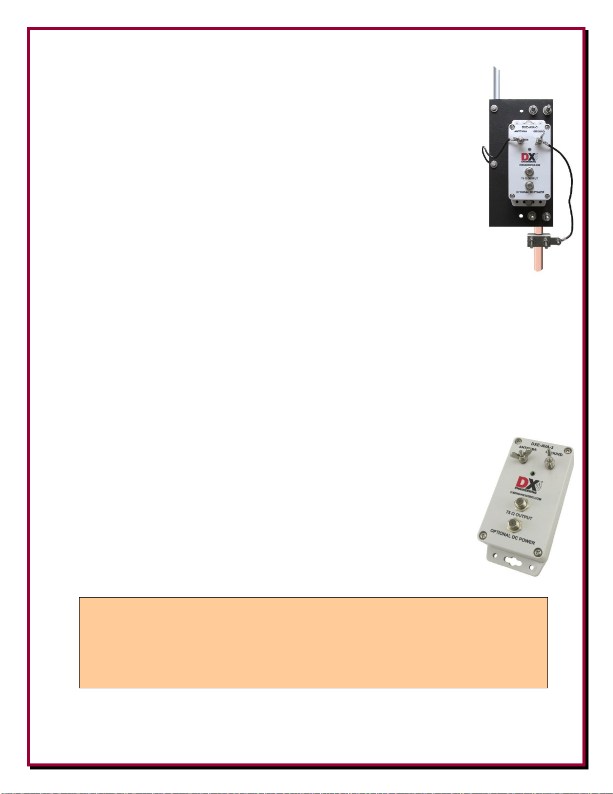
DXE-RSEAV-1
shown with optional ground rod
© DX Engineering 2022
1200 Southeast Ave. - Tallmadge, OH 44278 USA
Phone: (800) 777-0703 ∙ Tech Support and International: (330) 572-3200
E-mail: DXEngineering@DXEngineering.com
- 2 -
Introduction
This manual covers both the DXE-RSEAV-1 and the DXE-RSEAV-1FVI. The DXE
RSEAV-1FVI is exactly the same but comes with the DXE-FVI-1 DC Power Injector.
Class leading performance makes the DXE-RSEAV-1 Receive Short Element Active
Vertical Antennas the best choice on the market for VLF through HF reception, including
long distance AM broadcast, Medium Wave and Shortwave (SWL), new low frequency
Amateur bands, DXing, contesting and everyday HF operations.
DX Engineering Receive Short Element Active Vertical Antennas (RSEAV) offer
excellent low noise radio frequency reception from below 100 kHz to above 30 MHz. They
include a high quality three-section 8.5 ft. (2.6m) aluminum tubing whip, mounting plate
and the all new Active Matching Unit DXE-AVA-3 (also sold separately). When deployed
in the appropriate location, RSEAV antennas provide significantly better weak signal
reception than other actives and full size transmit-capable antennas due to reduced noise
and lower spurious signal interference, making them the best choice on the market for
DXing and contesting in Amateur Radio, and for long distance AM and Shortwave Listening (SWL).
Each Receive Short Element Active Vertical Antenna is intended to be mounted on a ground rod at ground
level in a clear area away from all metal, towers and other antennas. They are sold individually and in sets of
2, 3, 4 and 8 elements for use in phased array systems.
At the heart of the RSEAV Antennas is the DXE-AVA-3 Active Matching Unit. Its state-of-the-art
broadband operational amplifier design works as a high impedance buffer for the connection to a short
element of 6 to 24 feet. It achieves unparalleled weak signal reception with these features and benefits:
• Ultimate frequency coverage of 40 kHz* to 30 MHz for VLF through HF (including the 2200m and
630m Amateur bands)
• High Third Order Intercept (TOI) Performance +39dBm for superior strong signal handling equal to top
transceivers
• Consistent unit to unit gain for greatly improved array performance
• Virtually Flat Gain (+/-0.4 dBm) across the entire frequency range
• Internally settable gain (default -6, 0, or +6 dBm) for different ambient noise
locations and element sizes
• Direct DC via second F connector – internal settable choice for separate DC and RF
coaxial cables for best performance, or standard Bias Tee DC on the RF coax
• Each DXE-AVA-3 Active Matching Unit operates on 12 -15 VDC at 25mA
• Element is grounded when power is removed
• 75 ohm F connectors support field serviceable RG-6 Quad Shield suitable up to 1,000
feet for VLF through HF
*Frequency coverage below 100 kHz requires Direct DC on a separate DC only coaxial cable.
THIS IS A RECEIVE-ONLY SYSTEM
You should never attempt to transmit through the system.
The use of bypass relays and sequential timing is required to avoid damage to the receiver and active
antennas in the proximity of transmit antennas.
Do NOT place any active receive system on the same mast or tower as the transmit antenna.

- 3 -
Features
Receive Short Element Active Vertical RSEAV Antenna Sets offer these features:
• Long Life − High quality stainless steel mounting hardware
• Compact − Three piece aluminum 8.5 ft. element has low visual and environmental impact
• Ideal for portable use; easy to transport
• Easy Mounting and Installation Flexibility − Pre-drilled insulated mounting plate and included
stainless steel U-Bolt Saddle clamps for mounting to your ground rod
Location Considerations
The best place to install your active antenna is where you have the recommended space
away from power lines and away from your house, tower or any structures which are
excellent sources of noise. Even passive wiring in a wood building, a metal building or
metal fencing can act as a pickup antenna that can re-radiate noise.
The RSEAV antennas can be affected by atmospheric and ambient noise. Local noise
can be random or directional in nature. Every effort must be made to locate sources of
noise that could be eliminated at the source. Dimmer switches, electric timers,
photocell-operated security lights, and many other items can be sources of unwanted
noise. Now obsolete plasma monitors and television receivers are a known generator of
unwanted noise interference. Most modern LED or LCD flat panel televisions are not
broadband noise generators.
If the noise source is external and single directional in nature, using two DXE-
RSEAV-1 antennas in conjunction with the DXE-NCC-2 Receive Antenna Phasing
Controller could allow the user to phase out the noise being received. Large transmit
antennas are also very good source of re-radiated noise. A DXE-RSEAV-1 or the
DXE-AVA-3 cannot be mounted on, or near, a mast or tower due to induced noise
and potential RF overload.
Ideally, your receive antenna should be a minimum of 1/2-wavelength away from any
transmit antenna (on the lowest frequency) to avoid mutual coupling and the transfer of
any noise being re-radiated by the transmit antenna. If the receive antenna is located
1/10-wavelength to 1/2-wavelength from a transmitting antenna, the AVA-3 Active
Matching Unit must be powered off at least 5 ms before transmitting on the transmit
antenna. However, with an Active antenna less than 1/2-wavelength away, noise
coupling from the nearby transmit antennas becomes more pronounced. At frequencies
above 25 MHz, the active element length becomes a partial wavelength, increasing
noise coupling and pattern distortion.
When installed closer than 1/2-wavelength on the lowest frequency from a transmit
antenna, to assure highest protection for the active antenna, a DXE-TVSU-1B Time
Variable Sequencer Unit should be used to ensure the correct transmit-to-receive
switching. The RSEAV series antenna grounds the element when power is turned off.

- 4 -
General Information
This compact receiving antenna system operates over a very wide bandwidth with superior strong signal
performance. The output Third Order Intercept (TOI) rating of +39 dBm is significantly better than most
aftermarket preamplifiers and receivers - making it one of the cleanest active antennas on the market,
reducing or eliminating spurious signals.
Feedline decoupling, absent in some other popular designs, is also exceptionally good. Decoupling the shield
greatly reduces feedline conducted noise and unwanted signal interference.
The DXE-AVA-3 Active Matching Unit achieves unparalleled weak signal reception from 40 kHz* to 30
MHz. It may be used for VLF through HF reception with short metal or wire elements that range from less
than 6 feet up to 24 feet. The DXE-AVA-3 has a myriad of broadband RF applications as a high impedance
buffer between a physically small antenna element and the receiver.
DXE-RSEAV-1 – Single Active Antenna with no power source included; intended for use with devices that
send +13.8 Vdc on the RF coaxial cable, such as DXE-RTR-2 or DXE-NCC-2. Also, this model is for those
who will be using the Direct DC feature of the second F connector to power the DXE-AVA-3 with DC on a
separate coaxial cable. The DXE-RSEAV-1 includes:
DXE-AVA-3 Active Matching Unit
Non-conductive mounting plate
High quality Aluminum 3-piece antenna elements, 8 feet 6 inches long
Pair of Element connection wires, with ring and fork terminals
Stainless steel clamps and hardware
DXE-RSEAV-1FVI – Single Active Antenna that includes a bias tee and power source; for use with any
receiver or a transceiver with a receive antenna (RX ANT) input. May be used on any transceiver with the
optional DXE-RTR-2 Modular Receive-Transmit Interface
DXE-AVA-3 Active Matching Unit
Non-conductive mounting plate
Aluminum 3-piece antenna element, 8 feet 6 inches long
DXE-FVI-1 - Feedline Voltage Injector − powers the matching system and provides radio
connections
Includes a US plug wall transformer; 120 Vac 60 Hz to +12 Vdc, nominal
Stainless steel clamps and hardware
Using the Active Receive Verticals in a 4 Square or 8 Circle Array
Use the DX Engineering Receive Four Square System and four RSEAV-1 Antennas (DXE-RSEAV-4) to
configure a four square vertical array. Power and receiver connections are provided through the Four Square
system. Use the Receive Eight Circle system and eight RSEAV-1 Antennas (DXE-RSEAV-8) to configure
an eight circle receiving array. Power and receiver connections are provided through the Receive Eight
Circle system.
Using the Active Receive Verticals with the DXE-NCC-2
The DXE-RSEAV-2P Active Receive Vertical Antenna Set (two RSEAV-1 Antennas) and a DX
Engineering NCC-2 Receive Antenna Phasing Unit are used as a steerable dual vertical array for weak signal
and DXing. RSEAV Active Receive Verticals must be at least 1/10-wavelength away from any transmit
antenna. The NCC-2 switches the power off during transmit. This configuration allows the operator to
selectively null out interference, and thereby enhance the desired received signal direction ability. Every
radio manufacturer and every amateur radio operator's location is different. Refer to the DXE-NCC-2
manual for details. Also, you should consult your radio manufacturer's manual for details and further
requirements.

- 5 -
DXE-AVA-3
Active
Matching
Unit
Non-
conductive
Mounting
Plate
8-1/2 Foot
Aluminum Antenna
Element with
Connection Wires
DXE-FVI-1
Voltage
Injector
+12 Vdc
AC Adapter
(required
for FVI-1)
DXE-SSVC-1PG
Stainless Steel
Ground Clamp
DXE-SSVC-1P
Stainless Steel
Clamps
DXE-RSEAV-1
1 1 1 - - 1 2
DXE-RSEAV-1FVI
1 1 1
1 1 1
2
WARNING!
INSTALLATION OF ANY ANTENNA NEAR POWER LINES IS DANGEROUS
Warning: Do not locate the antenna near overhead power lines or other electric light or power circuits, or
where it can come into contact with such circuits. When installing the antenna, take extreme care not to
come into contact with such circuits, because they may cause serious injury or death.
Manual Updates
Every effort is made to supply the latest manual revision with each product. Occasionally a manual will be
updated between the time your DX Engineering product is shipped and when you receive it. Please check the
DX Engineering web site (www.DXEngineering.com) for the latest revision manual.
Basic Tools Required
1/4”, 3/8”, 5/16", 7/16", 1/2" wrenches or nut drivers, and a 5/8" wrench
# 2 Phillips Head Screw Driver
7/64” and 3/32” Allen Wrenches - Included in this kit -
Knife or Scissors for cutting the weatherproofing tapes.
Parts needed but not included:
JTL-12555 Jet-Lube SS-30 for antenna elements and all stainless steel hardware
LCT-37534 Loctite Dielectric Grease used on F-Connectors
TES-2155 3M Temflex Tape used to weatherproof the F-Connectors
TES-06143 3M Super 88 Vinyl Electrical Tape - overwrap for UV protection
Ground Rod 1/2” to 3/4” OD used for installing the unit and mounting plate in place
NOTE: The following describes the use of DXE-SSVC-1P and DXE-SSVC-1PG V-Clamps that are
included with the RSEAV. These are used for mounting the AVA-3 on a typical customer
supplied ground rod from 1/2" OD to 3/4" OD.
---------------------
If you plan to mount the RSEAV to a larger mounting mast, you will need two optional DXE-
SSVC-150P and one optional DXE-SSVC-150PG V-Clamps which will accommodate a
mounting mast that is 1" OD to 1-1/2" OD.
AVA-3 Configuration: Internal Jumper Settings for RF Gain (J1) and DC
Supply Selections (J2 and J3)
Before mounting your state-of-the-art AVA-3 Active Matching Unit, understanding the correct choices for
internal jumper settings is vitally important.

- 6 -
RF Gain Selection - J1
The DXE-AVA-3 features internal jumper selection of relative gain settings, with the factory default of 6dB, as well as 0dB and +6dB settings, to match the ambient noise conditions for the antenna location, and to
adjust for the size of the antenna element to be used. Remove the cover from the AVA-3 to allow access to
the jumpers. Set the jumpers to the desired positions
as described.
As a rule of thumb, always use the lowest gain
setting that works for the application. This is
usually the setting with the minimum discernible
ambient background noise that is at or just above
the noise floor of the receiver. This setting will
allow the greatest signal-to-noise improvement for
all signals, especially weak signals.
The default jumper setting of -6 dB gain is the best
choice for the majority of installations, including
those with the RSEAV-1 8.5 ft. antenna elements. This lowest gain setting
is also the best choice for receiving locations where AM Broadcast (MW)
stations are within 10 miles (16 km).
As the gain setting is increased in the AVA-3, the possibility for RF
overload and distortion increases at extremely high signal input levels.
Therefore, in locations with multiple transmitters or high ambient local
noise, do not use the +6dB setting. Longer elements, such as 20 to 24 ft.,
that are typically used for low band, AM, LF and VLF will also produce a
higher ambient local and atmospheric noise floor, especially at 0dB or
+6dB settings.
DC Power Source Selection J2 and J3 - The factory default setting is DC
over the RF coax. You can also select direct DC via a separate coax. In
either case - when power is supplied to the AVA-3 - the Green LED will be
ON.
The versatility of the AVA-3 includes the option of using the Direct DC F connector for installations where
the use of the AVA-3 internal Bias Tee, is undesirable.
NOTE: For optimal receive performance, especially on VLF frequencies from 40 to 200 kHz,
Direct DC is required. For installations where the DC is intended to applied at all times for
uninterrupted reception, such as for skimmers and remote receivers, Direct DC via the separate
coax to the “OPTIONAL DC POWER” input is recommended, so the “75 Ω OUTPUT” coax
carries only RF.

- 7 -
For average Amateur installations for 1.8 to 30 MHz intermittent
operations, where the DC supply is normally turned off, standard
internal bias tee DC over the RF coax is perfectly acceptable.
The internal three-pin jumper headers J2 BT and J3 EXT DC, located
next to the PC board F connector terminals, are used to select the DC
power for the AVA-3. Both headers require identically jumpered
pins in order to function.
The Default setting as supplied is with both
pins 1 and 2 are connected together (jumpers
installed) on both J2 and J3 headers, the bias
tee provides power from the “75 Ω OUTPUT”
coax F connector.
When pins 2 and 3 are connected together
(jumpers installed) on both headers, the
separate “OPTIONAL DC POWER” F
connector supplies DC power to the AVA-3
circuitry. In that case the center pin of the coax
is +13.8 VDC and the shield ground is 0 VDC. When this method of powering the
AVA-3 is chosen, the “75 Ω OUTPUT” coax F connector handles only the received
RF.
When the jumpers are set, replace the cover ensuring the weep holes are toward the
bottom (AVA-3 is mounted vertically as shown above).
Weep holes
Assembly
The assembly described is for a single DXE-RSEAV-1. Use JTL-12555 - Jet-Lube SS-30 on the joints
between the antenna elements and on all stainless steel hardware threads to prevent galling and to ensure
proper torque. NEVER use SS-30 or any anti-seize on RF coaxial connectors.
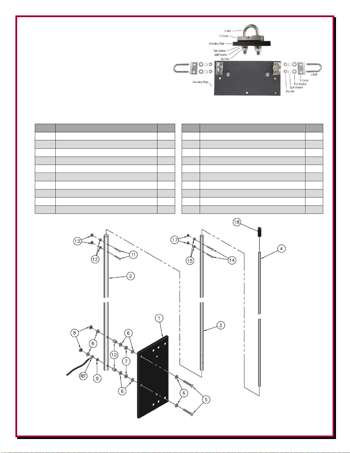
Orient the black mounting plate with the antenna mounting holes close to the top, as shown in Figure 1.
Mount the AVA-3 matching unit using the 1" hex head bolts, flat washer under each bolt, flat and split
washer under each hex nut.
Figure 1
- 8 -
Loosely install the two stainless steel U-Clamps on
the black mounting plate using the U-Bolt, VClamp, Flat washers, Split Washers and Hex nuts
as shown in Figure 2.
Figure 2
Antenna and Antenna Mounting Plate Parts List
Item
Description
QTY
Item
Description
QTY
1
Mounting Plate, Black
1
11
#6-32 x 3/4” Socket Head Cap Screw
2 2 1/2” Tube, Drilled
1
12
#6 Flat Washer
2 3 3/8” Tube, Drilled
1
13
#6-32 Nylon Lock Nut
2 4 1/4” Tube, Drilled
1
14
#4-40 x 1/2” Socket Head Cap Screw
2 5 #10-24 x 1-1/2” Hex Head Cap Screw
2
15
#4 Flat Washer
2 6 #10 Flat Washer
8
17
#4-40 Nylon Lock Nut
2 7 #10-24 Hex Nut
2
18
1/4” Vinyl Cap
1 8 #10-24 Nylon Lock Nut
2
REF
#10 Round Term with short wire & Forked Term
1 9 #10 External Tooth Washer
1 - 7/64” Allen Hex Wrench
1
10
5/16” Aluminum Spacer, 11/32” long
2 - 3/32” Allen Hex Wrench
1
Figure 3

- 9 -
NOTE: The parts list (above) and drawing only show the parts for the 3-piece antenna and antenna
mounting plate. Other parts in this kit include the AVA-3 unit, mounting hardware, two ground rod
mast mounting clamps and one ground clamp with tab which are described in the following
assembly.
Bottom Antenna Element Assembly
Refer to the drawing shown in Figure 3 and Figure 4 for the antenna assembly.
Figure 4
Figure 4
Install 2 hex head bolts (#10-24 x 1-1/2” long) in the mounting plate using flat washers and hex nuts
as shown in Figure 5, tighten in place.
Figure 5
- 10 -
Place a flat washer and a spacer on each of the hex head bolts. The
bottom antenna element has larger holes on one side, these
larger holes face the spacers. The bottom antenna element is
installed so the spacers are inside of the element. Refer to Figures 3
& 4 for details.
On the bottom hex head bolt, install an external tooth washer, the
short antenna wire with a ring terminal, followed by a flat washer,
split washer and a hex nut as shown in Figure 5. Note the direction
of the wire in the photo. On the top hex head bolt, install a flat
washer, split washer and a hex nut. Tighten in place.
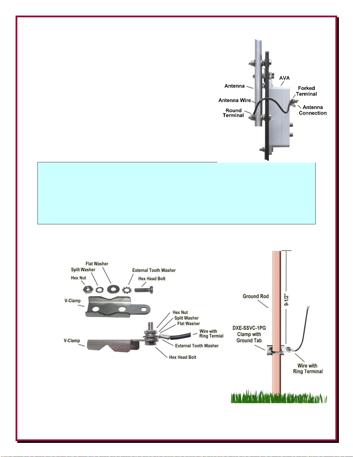
The other end of the short antenna wire has a fork lug, is connected
to the ANTENNA on the AVA-3 as shown in Figure 6 between
the two flat washers. Tighten in place.
Figure 6
NOTE: The following describes the use of DXE-SSVC-1P and DXE-SSVC-1PG V-Clamps that are
included with the RSEAV. These are used for mounting the RSEAV on a typical customer
supplied ground rod from 1/2" OD to 3/4" OD.
---------------------------------
If you plan to mount the RSEAV to a larger mounting mast, you will need two optional DXE-
SSVC-150P and one optional DXE-SSVC-150PG V-Clamps which will accommodate a
mounting mast that is 1" OD to 1-1/2" OD.
Mounting the V-Clamp with Tab to a Ground Rod
Attach the longer wire with ring terminal using the hardware described
in Figure 7 to the tab on the included DXE-SSVC-1PG.
Figure 7
Figure 7
Install the customer supplied 1/2” to 3/4” OD by 4 to 6 ft. ground rod
where the Active Receive Antenna will be placed. Leave approximately
16 inches of the ground rod or mounting mast above ground level to
mount the antenna. Depending on soil conductivity, increasing ground
rod depth beyond a few feet for an active receive antenna rarely
- 11 -
improves RF grounding because skin effect in the soil prevents current from flowing deep in the soil.
Avoid ground rods less than 1/2" in diameter.
Install the DXE SSVC-1PG on the
ground rod approximately 9-1/2” from the
top of the ground rod as shown in Figure
9. Note the position of the DXE-SSVC1PG and the ground wire tab in as
compared to the
mounting plate of the active Figure
9antenna (Refer to the completed
assembly in Figure 9). Use the included
U-Bolt, flat washers, split
Figure 9 washers and hex nuts. Figure 10 - three views
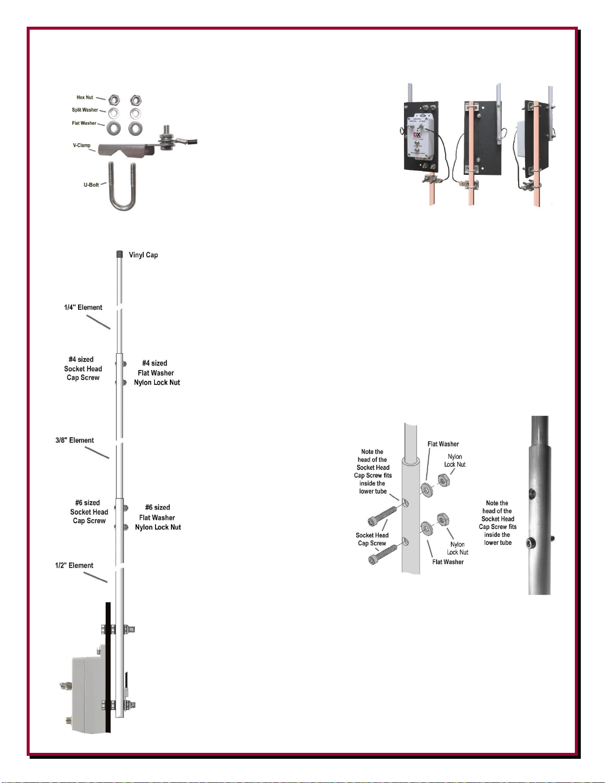
Mount the AVA-3 assembly to the ground rod as shown in Figure 10. Position
the assembly on the ground rod and adjust the height so the ground rod top is
not higher than the black insulated panel. This prevents unwanted interference
with the active element. Tighten the two U-Clamps to hold the assembly in
place.
Connect the second (longer) wire coming from the ground tab to the AVA-3
antenna GROUND connection, use the wing nut and hand tighten only. The
forked terminal goes between the two washers on the GROUND terminal as
shown in Figure 10.
Installing the upper two Antenna Elements
The upper two elements are
installed to the antenna element
that is in place on the black
mounting plate. 3/8” element fits
inside the 1/2” element mounted
to the black mounting plate.
Use the #6 hardware and the
included Allen wrench to secure
this element in place. Note: The
head of the socket head cap
screws will fit inside of the
larger hole and make contact
with the element that was
inserted. Refer to Figure 11 for
details. The overall length
assembled is 102”.
The upper 1/4” element fits inside the 3/8” element, Use the Figure 11
#4 hardware and the included Allen wrench to secure the
upper element in place. Install the black vinyl cap in place
on the top element.
- 12 -
Providing a Good RF Ground
This Active Vertical Antenna works well with just a single copper ground rod used as the mounting
rod.
You can test the quality of the ground when using only one ground rod. Tune in an AM or low band
steady signal that is not Skywave and note the signal level. Then, attach 15 feet of wire to the ground
terminal or ground rod, laid out in a straight line away from the coaxial feedline. If you observe a
change in signal or noise level, you need to improve the grounding.
A second rod spaced a few feet away from, and connected to the first one should correct the
problem. If a good ground cannot be established, use a DXE-RFCC-1 Feedline Current Choke that
will further decouple the feedline from the antenna and reduce common mode current and associated
noise from the feedline.
If you locate your ground mounted antenna where ground rods cannot be used effectively, you must
use a radial system. A suitable radial system consists of four, eight or twelve equally spaced radials,
with each radial being at least 15 feet long, but not longer than 20 feet.
Only if the antenna is located over rock, on a roof, or otherwise installed where conductive soil
conditions do not exist, you must use a ground screen. Welded-wire galvanized screens are okay for
this receive antenna only and are not recommended for transmit antennas. Screen radius must at least
equal the element height and be placed around the antenna as symmetrically as possible, but should
not exceed a radius of 20 feet. The AVA-3 negative terminal or its radial system should never be
connected to any metal structure, to assure low noise operation.
Do not use elevated radials or grossly asymmetrical radial configurations. The ground system is an
integral part of this receiving system, and if it is asymmetrical or exhibits pronounced resonances,
the antenna system may not function properly. For multiple RSEAV Antennas used in an array, each
element must have the identical number of ground rods and radials, if used.
Connections
For single antenna DXE-RSEAV-1FVI Antenna installations, the DXE-FVI-1 Feedline
Voltage Injector is installed near the operating position. By default settings of the AVA-3
internal jumpers, the FVI-1 powers the AVA-3 Active Matching Unit through the RF
feedline connection. See Figure 12.
If possible, bury the feed line for some distance from the antenna. This helps to decouple
the feedline from unwanted noise. A DXE-RFCC-1 Receive Feedline Choke will also
ensure feedline decoupling.
Connect a suitable 75 Ω feedline to the type F connector OUTPUT. Leave a small loop
in the feedline to relieve stress on the AVA-3 connection and securely attach the feedline
to the ground rod below the mounting plate.
Figure 12
The feedline connectors must remain dry. Do not place any intentional DC shorts or
opens on the feedline between the FVI-1 and the AVA-3. This includes lightning
arrestors, splitters, or any other accessory not intended for feedlines that carry power or
control voltages.
- 13 -
Weatherproof the coaxial cable connection using Loctite Dielectric Grease (LCT-37534) and if additional
weatherproofing is required for your installation, use Temflex Tape (TES-2155) and Vinyl Tape (TES-
06132) as a UV overwrap.
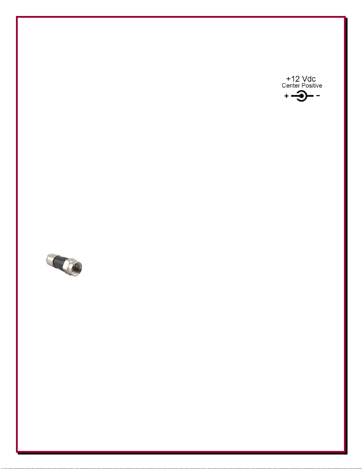
For the DXE-RSEAV-1FVI the included 120 Vac 60 Hz, to 12 Vdc wall transformer DC
power supply connects to the +12 Vdc input. The center of the 2.1mm power plug is
positive. Larger power supplies or station power may also be used provided there is an inline 1 ampere fast-blow fuse. The RCA phono jack on the DXE-FVI-1 connects to the
receiver input with a customer supplied cable.
Active antenna circuitry needs a good voltage supply to operate properly. Supplied power needs to be +11.5
to +15 VDC, 25 mA minimum at each active (under load).
The DXE-FVI-1 is not included or used in the multi-element vertical sets. Power is applied to the coax when
Bias Tee Enable internal jumpers are set in the DXE-NCC-2, or by the Four-Square or Eight Circle Array
Relay Unit. The AVA-3 can also be powered by a separate DC coaxial cable to the Optional DC Power typeF connector, with internal jumpers reset; see page 8.
Coaxial Cable Feedline
A good flooded 75 Ω feedline cable is recommended for use with the RSEAV systems. DXE-RG6UFQ
Flooded 75 Ω Quad Shield Coaxial Cable has improved shielding. Flooded style cables have the distinct
advantage of automatically sealing small accidental cuts or lacerations of the jacket. Flooded cable also
prevents shield contamination and has a gummy liquid inside that seals cuts or nicks, displaces water, and
can be direct buried.
The feedline carries the RF and is used to provide power for the AVA-3 Active
Matching Unit. DXE-EX6XL-25 Compression type F connectors are recommended for
quad shield coax to ensure high quality and weather resistant feedline connections. Use
the proper tool to crimp these connectors.
To help decouple the feedline from radiated noise, bury the feedline for some distance from the antenna
when the feedline reaches the ground. A DXE-RFCC-1 DX Engineering Receive Feedline Choke will also
ensure feedline decoupling, which may be installed in-line, preferably at the station end.
To seal out moisture, the use of Dielectric Grease is recommended for type F connectors, such as Permatex
PTX-22058 or Loctite LCT-37534.
Never use anti-seize on any coaxial RF or power connector.
Troubleshooting Information
When using the DXE-RSEAV-1 Active Receive Vertical antenna, the actual received signal level will be
lower than a transmit antenna. Depending upon a few variables, including the frequency of the measured
signal, your DXE-RSEAV-1 Active Receive Vertical is probably operating normally.
The DXE-RSEAV-1 is designed to be a very low to no gain, low noise system for greatly improved signalto-noise performance over a very wide range of frequencies.

- 14 -
The installation location should be away from towers, transmitting antennas, metal structures and metal
fencing in order to take advantage of the DXE-RSEAV-1 Active Receive Vertical antenna capabilities.
Normally the Active Receive Vertical antenna will properly reject high angle sky wave signals, which is the
goal for a low band DXing receive antenna. Low angle, long range DX signals are easier to copy using an
Active Receive Vertical antenna system.
Here are a few things that you may check to be sure that the Active Receive Vertical antenna is operating
normally:
1) Measure the voltage arriving at the antenna end of the feedline. The DXE-FVI-1 Feedline Voltage
Injector unit should be providing approximately 12 to 14 Vdc, and the Active Matching Unit requires at
least +11.5 Vdc or more for proper function. Bench tests on the DXE-RSEAV-1 and AVA-3 are
normally about 25 mA, so with some voltage drop on the line, 40 to 50 mA should be okay. If the
measured voltage at the end of the line is under +11 Vdc, then there may be a resistive connection along
the feedline. As a point of reference, a good flooded 75 Ω feedline cable is recommended for use with
the RSEAV systems. DXE-RG6UFQ Flooded 75 Ω Quad Shield Coaxial Cable has improved shielding.
Flooded style cables have the distinct advantage of automatically sealing small accidental cuts or
lacerations of the jacket. Flooded cable also prevents shield contamination and has a gummy liquid
inside that seals cuts or nicks, displaces water, and can be direct buried. This low-loss cable features dual
shields and an 82% Velocity Factor and is ideal for long runs on four and two antenna arrays without
trouble.
2) Double check the jumpers inside the AVA-3 unit at the base of the Active Receive Vertical antenna. As
shown in this manual, the default condition for jumpers installed onto pin 1 and 2 of both J2 and J3
should be found for normal FVI-1, DC on the RF coax operation.
3) After tuning in a steady, non-fading reference signal on the broadcast band and noting the signal level,
add 4 radials that are about 15 feet long to the negative terminal ground rod connection on the AVA-3. If
this significantly increases signal level, then adding another ground rod and/or more radials, as described
in this manual should improve your signal results for all bands.
4) When disconnecting the power to the Active Receive Vertical antenna, the green LED will turn off and
there should be very little or no signal. In other words, verify that powering the RSEAV Antenna results
in improved signal level and signal-to-noise enhancement, without a large increase in noise. If there is
almost the same amount of signal without and with power, there are two possible issues:
a) Proper operating voltage is not arriving at the Active Receive Vertical antenna, or;
b) If you seem to have a high amount of common mode signal or noise arriving on the shield of the
Active Receive Vertical antenna feedline that is running on or above ground or similar noise as
your transmit antenna. For some installations the DXE-RFCC-1 Receive Feedline Current
Choke may help. The use of the DXE-RFCC-1 Receive Feedline Current Choke will remove
common mode signal and noise collected by the shield of the feedline in order to realize normal
signal-to-noise improvements available from an Active Receive Vertical antenna.
Given that all connections are good, voltage at the AVA-3 is good and that the other tests indicate everything
is normal, it is likely the signal level you are receiving is normal.
In most circumstances, the DXE-RSEAV-1 Antenna used singly, or in two, four and eight element arrays,
offers low level low band signals that have significantly improved signal-to-noise. It is sometimes necessary
to enhance these results to listening levels by using the DXE-RPA-2 Modular Receive Preamplifier in line,

- 15 -
without losing the signal-to-noise benefits of the no-gain Active Receive Vertical antenna. Only the DXE-
RPA-2 operates with a third order intercept and dynamic range that is far superior to most receiver frontends.
Simultaneous use of the external preamplifier as well as using receiver internal attenuation and/or RF Gain
reduction along with AF Gain increase can provide substantially improved signal readability. Often, external
preamplification is not required for best results.
DXE-AVA-3

- 16 -
Maintenance
Verify weep holes (that face downward) on the AVA-3 are kept clear and open to allow any
moisture build up inside the AVA-3 to drain out. Verify coax cable(s) are properly weatherproofed
to keep moisture out. Use the included black vinyl cap to cover the optional DC power F-Connector
if it is not being used.
Technical Support
If you have questions about this product, or if you experience difficulties during the installation,
contact DX Engineering at (330) 572-3200. You can also e-mail us at:
DXEngineering@DXEngineering.com
For the best service, please take a few minutes to review this manual before you call.
Warranty
All products manufactured by DX Engineering are warranted to be free from defects in material and workmanship for a period of one (1) year from
date of shipment. DX Engineering’s sole obligation under these warranties shall be to issue credit, repair or replace any item or part thereof which is
proved to be other than as warranted; no allowance shall be made for any labor charges of Buyer for replacement of parts, adjustment or repairs, or
any other work, unless such charges are authorized in advance by DX Engineering. If DX Engineering’s products are claimed to be defective in
material or workmanship, DX Engineering shall, upon prompt notice thereof, issue shipping instructions for return to DX Engineering (transportationcharges prepaid by Buyer). Every such claim for breach of these warranties shall be deemed to be waived by Buyer unless made in writing. The above
warranties shall not extend to any products or parts thereof which have been subjected to any misuse or neglect, damaged by accident, rendered
defective by reason of improper installation, damaged from severe weather including floods, or abnormal environmental conditions such as prolonged
exposure to corrosives or power surges, or by the performance of repairs or alterations outside of our plant, and shall not apply to any goods or parts
thereof furnished by Buyer or acquired from others at Buyer’s specifications. In addition, DX Engineering’s warranties do not extend to other
equipment and parts manufactured by others except to the extent of the original manufacturer’s warranty to DX Engineering. The obligations under
the foregoing warranties are limited to the precise terms thereof. These warranties provide exclusive remedies, expressly in lieu of all other remedies
including claims for special or consequential damages. SELLER NEITHER MAKES NOR ASSUMES ANY OTHER WARRANTY
WHATSOEVER, WHETHER EXPRESS, STATUTORY, OR IMPLIED, INCLUDING WARRANTIES OF MERCHANTABILITY AND
FITNESS, AND NO PERSON IS AUTHORIZED TO ASSUME FOR DX ENGINEERING ANY OBLIGATION OR LIABILITY NOT STRICTLY
IN ACCORDANCE WITH THE FOREGOING.
©DX Engineering 2022
DX Engineering®, DXE®, DX Engineering, Inc.®, Hot Rodz®, Maxi-Core®, DX Engineering THUNDERBOLT®, DX Engineering Yagi Mechanical®,
EZ-BUILD®, TELREX®, Gorilla Grip® Stainless Steel Boom Clamps, Butternut®, SkyHawk™, SkyLark™, SecureMount™, OMNI-TILT™, RFPRO-1B®, AFHD-4® are trademarks of PDS Electronics, Inc. No license to use or reproduce any of these trademarks or other trademarks is given or
implied. All other brands and product names are the trademarks of their respective owners.
Specifications subject to change without notice.
 Loading...