

Page 1

Aluminum Radio RF Ground Plane Kit
DXE-RGP-SA, DXE-RGP-SAB
DXE-RGP-MA, DXE-RGP-MAB
DXE-RGP-LA, DXE-RGP-LAB
DXE-RGPA-INS Revision 0
DXE-RGP-MAB shown with an
Icom IC-7300 (not included) and
Tinned Copper Braids (not included)
© DX Engineering 2022
1200 Southeast Ave. - Tallmadge, OH 44278 USA
Phone: (800) 777-0703 ∙ Tech Support and International: (330) 572-3200
Fax: (330) 572-3279 ∙ E-mail: DXEngineering@DXEngineering.com
Page 2

Introduction
Part Number
Description
DXE-RGP-SA
Radio RF Ground Plane, Small Aluminum Sheet 13” x 10”x0.063”, with Hardware
DXE-RGP-SAB
Radio RF Ground Plane, Small Aluminum Sheet 13”x10”x0.063”, 12.25”x10.5”x0.5” MDF Board w/ Hardware
DXE-RGP-MA
Radio RF Ground Plane, Medium Aluminum Sheet 16” x 16”x0.063”, with Hardware
DXE-RGP-MAB
Radio RF Ground Plane, Medium Aluminum Sheet 16”x16”x0.063”, 16.5”x15.25”x0.5” MDF Board w/ Hardware
DXE-RGP-LA
Radio RF Ground Plane, Large Aluminum Sheet 20” x 20”x0.063”, with Hardware
DXE-RGP-LAB
Radio RF Ground Plane, Large Aluminum Sheet 20”x20”x0.063”, 20.5”x19.25”x0.5” MDF Board w/ Hardware
DX Engineering Radio RF Ground Plane Kits provide an effective method of reducing stray RF
pickup by equipment and interconnecting cables. Used under and in back of equipment, this 1/16
inch thick, pre-drilled aluminum sheet creates an RF reference plane that
is typically connected to the existing grounding bus, or it may be used as
a grounding bus. As described in the ARRL’s “Grounding and Bonding
for the Radio Amateur” by H. Ward Silver, N0AX; a large surface area
of metal improves upon the single conductor grounding bus by
equalizing the RF E-field (electric field) around equipment and attached
cables. This reduces voltage differences between pieces of equipment
and associated currents that cause RF interference to transceivers,
microphones and accessories. The reduction in RF interference improves
both transmitted and received signal quality.
As used by top contesters and DXers alike, this type of flat metal sheet
placed under equipment, along with physically short grounding braids,
wires and interconnection cables can significantly reduce the RF voltage
differences between cables and equipment. The chance of RF trouble in
your equipment is reduced by installing DX Engineering Radio RF
Ground Plane Kits in your station.
NOTE: These are indoor radio equipment RF ground planes, which are not to be confused with a
ground plane or radial system on a vertical antenna. The only interconnection between any antenna
and this Radio RF Ground Plane is incidental, through the shield of properly protected and
grounded coaxial cable which is connected to the station RF bonding bus and grounding system.
Radio RF Ground Plane Kits Available
The Radio RF Ground Plane Kits are available in six versions; three sizes of aluminum plate with
hardware and the same three sizes aluminum plates with companion mounting boards made of
Medium Density Fiberboard (MDF), with hardware. All kits are intended for indoor use only:
All dimensions are in Inches
2
Page 3

Ground Plate Size Information
Transceiver Model
Transceiver
Width
Transceiver
Depth
DXE-Aluminum Plate
DXE Part Number
DX-SR8T
9.500
11.500
10.00 X 13.00 - SMALL
DXE-RGP-SAB
DX-SR9T
9.500
11.500
10.00 X 13.00 - SMALL
DXE-RGP-SAB
IC-7100
11.500
12.500
16.00 X 16.00 - MEDIUM
DXE-RGP-MAB
IC-718
9.500
9.500
10.00 X 13.00 - SMALL
DXE-RGP-SAB
IC-7200
9.500
11.063
10.00 X 13.00 - SMALL
DXE-RGP-SAB
IC-7300
9.500
9.375
10.00 X 13.00 - SMALL
DXE-RGP-SAB
IC-9700
9.500
9.375
10.00 X 13.00 - SMALL
DXE-RGP-SAB
IC-7610
13.500
11.000
16.00 X 16.00 - MEDIUM
DXE-RGP-MAB
IC-7700
16.750
17.250
20.00 X 20.00 - LARGE
DXE-RGP-LAB
IC-7851
16.750
17.125
20.00 X 20.00 - LARGE
DXE-RGP-LAB
IC-9100
12.500
13.500
16.00 X 16.00 - MEDIUM
DXE-RGP-MAB
TS-2000
10.625
12.500
16.00 X 16.00 - MEDIUM
DXE-RGP-MAB
TS-2000X
10.625
12.500
16.00 X 16.00 - MEDIUM
DXE-RGP-MAB
TS-590SG
10.625
11.500
16.00 X 16.00 - MEDIUM
DXE-RGP-MAB
TS-890S
15.625
13.375
16.00 X 16.00 - MEDIUM
DXE-RGP-MAB
TS-990S
18.125
15.750
20.00 X 20.00 - LARGE
DXE-RGP-LAB
FT-450D
9.000
8.500
10.00 X 13.00 - SMALL
DXE-RGP-SAB
FT-991A
9.000
10.000
10.00 X 13.00 - SMALL
DXE-RGP-SAB
FTDX-1200
14.500
12.375
16.00 X 16.00 - MEDIUM
DXE-RGP-MAB
FTDX-3000
14.500
12.375
16.00 X 16.00 - MEDIUM
DXE-RGP-MAB
FTDX-5000MP
18.250
15.375
20.00 X 20.00 - LARGE
DXE-RGP-LAB
FTDX-101D
16.535
12.677
20.00 X 20.00 - LARGE
DXE-RGP-LAB
FTDX-101MP
16.535
12.677
20.00 X 20.00 - LARGE
DXE-RGP-LAB
101MP Speaker
6.3
12.677
10.00 X 13.00 - SMALL
DXE-RGP-SAB
FTDX-10
10.5
10.35
16.00 X 16.00 - MEDIUM
DXE-RGP-MAB
The following chart shows typical transceiver size information to help you choose the size
aluminum plate you require. You can also use two or more aluminum plates beside each other if
you need a larger aluminum plate area.
If your particular transceiver is not listed, just measure to determine the size you require.
The aluminum plates are also recommended for use with RF amplifiers, Tuners and any
All dimensions are in Inches
other amateur radio active components.
3
Page 4

Painting the Aluminum Plate
Kit Part Number
Aluminum
Ground Plane
MDF Board
#6 Self
Tapping
Screws
1/4-20
Hex
Bolt
1/4”
Hex
Nut
1/4”
Split
Washer
1/4” Ext
Tooth
Washer
1/4” Flat
Washer
DXE-RGP-SA
1
13” x 10”
- - -
4 4 4 4 8
DXE-RGP-SAB
1
12.25” x 10.5” x 0.5”
4
DXE-RGP-MA
1
16” x 16”
- - -
4 4 4 4 8
DXE-RGP-MAB
1
16.5” x 15.25” x 0.5”
4
DXE-RGP-LA
1
20” x 20”
- - -
4 4 4 4 8
DXE-RGP-LAB
1
20.5” x 19.25” x 0.5”
4
It is possible to spray paint on aluminum. The aluminum should be clean and dry, and an epoxy
primer may be applied before spray painting to promote adhesion. Make sure the paint is
specifically made to cover aluminum. Many brands and colors are available and they are readily
found at hardware stores.
Remove the plastic protection (if present) from the front of the aluminum plate and, while wearing a
particle dust mask and nitrile gloves, sand the surface with fine-grit sandpaper, taking great care to
sand the entire surface thoroughly. Once the sanding is completed, clean the surface with denatured
alcohol and a clean cotton rag or paper towels. Keep clean nitrile gloves on during this process to
ensure that the oils of your skin do not come in contact with the aluminum plate. Tape off the areas
where the connections are made to the aluminum plate to ensure adequate electrical/RF
connections.
Radio RF Ground Plane Kits - Parts List
All dimensions are in Inches
Tools Required
7/16” Nut Driver, 7/16” Wrench, Phillips Screw Driver
4
Page 5

Assembly
The following assembly uses the DXE-RGP-MAB Radio RF Ground Plane Kit with the MDF
Board and hardware. Also shown are optional DX Engineering Tinned Aluminum Braid straps.
1. Mount the Aluminum Sheet to the MDF Board using the four self tapping screws as shown
below.
Note: The Aluminum Ground Plane is longer than the MDF Board with the four larger holes for
grounding connections and multiple ground plane interconnections. This is done to allow room
for the hardware used to attach tinned copper braid, copper strap or wires to equipment and the
radio room single point ground.
2. Set your equipment in place on the RF Ground plane and measure the length(s) of Tinned Copper
Braid needed. Keep the lengths as short as possible.
3. Attach the Tinned Copper Braids to the
equipment and to the Aluminum Ground
Plane using the 1/4” stainless steel hardware
included in the kit. Use of the DXE-CCK
Copper Cleaning Kit or JTL-12555 JetLube-SS-30 is suggested.
Note: You can attach conductors to the Aluminum Ground Plate in different methods. Choose the
method that best suits your application. Once the equipment is attached, also run a heavy
conductor or copper strap as the ground line to the ground bus or to the single point ground
panel, such as the DXE-SPGP where cables enter the radio room and connect to protectors.
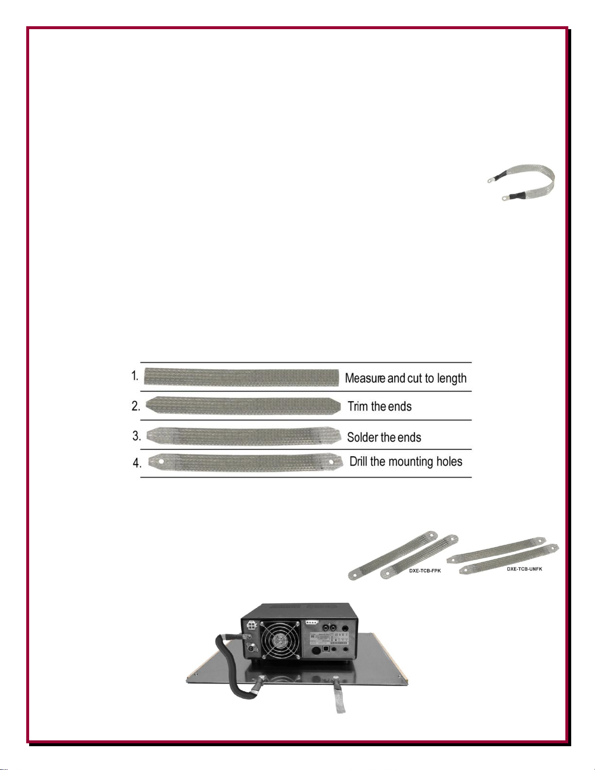
DXE-RGP-MAB shown with an optional
ICOM IC-7300 and optional
Tinned Copper Braids
Keep the braids as short as you can.
5
Page 6
Suggested Parts
DXE-CCK - Copper Cleaning Kit
JTL-12555 - Jet-Lube SS-30
DX Engineering Tinned Copper Braid Assemblies with 1/4” Ring Terminals - The
DX Engineering Tinned Copper Braided Straps come in various lengths and have Ring
Terminals soldered at each end. You can also get custom made assemblies to your exact
length specifications by using the Custom Cable Builder on the DX Engineering web
site.
You can also purchase the Tinned Copper Braid in various widths by the foot from DX Engineering
(DXE-TCB-038 / 050 / 063 / 075 / 100) and make them to your specified lengths.
A suggested method to make your own short custom length tinned copper braid jumpers:
1. Cut the Tinned Copper Braid to the length you want.
2. Trim
3. Solder each end.
4. Once the part has cooled, drill mounting 1/4” holes on each end.
This is ideal since you can easily make them short.
DX Engineering also has two feedpoint kits that have premade 1” wide Tinned Braided Straps that can be used as
well. DXE-TCB-FPK has one 8” and one 9” braid. The
DXE-TCB-UNFK has two 9” braids.
6
Page 7

Notes:
7
Page 8

Manual Updates
Every effort is made to supply the latest manual revision with each product. Occasionally a manual
will be updated between the time your DX Engineering product is shipped and when you receive it.
Please check the DX Engineering web site (www.dxengineering.com) for the latest revision manual.
Technical Support
If you have questions about this product, or if you experience difficulties during the installation,
contact DX Engineering at (330) 572-3200. You can also e-mail us at:
DXEngineering@DXEngineering.com
Warranty
All products manufactured by DX Engineering are warranted to be free from defects in material and workmanship for a
period of one (1) year from date of shipment. DX Engineering’s sole obligation under these warranties shall be to issue
credit, repair or replace any item or part thereof which is proved to be other than as warranted; no allowance shall be
made for any labor charges of Buyer for replacement of parts, adjustment or repairs, or any other work, unless such
charges are authorized in advance by DX Engineering. If DX Engineering’s products are claimed to be defective in
material or workmanship, DX Engineering shall, upon prompt notice thereof, issue shipping instructions for return to
DX Engineering (transportation-charges prepaid by Buyer). Every such claim for breach of these warranties shall be
deemed to be waived by Buyer unless made in writing. The above warranties shall not extend to any products or parts
thereof which have been subjected to any misuse or neglect, damaged by accident, rendered defective by reason of
improper installation, damaged from severe weather including floods, or abnormal environmental conditions such as
prolonged exposure to corrosives or power surges, or by the performance of repairs or alterations outside of our plant,
and shall not apply to any goods or parts thereof furnished by Buyer or acquired from others at Buyer’s specifications.
In addition, DX Engineering’s warranties do not extend to other equipment and parts manufactured by others except to
the extent of the original manufacturer’s warranty to DX Engineering. The obligations under the foregoing warranties
are limited to the precise terms thereof. These warranties provide exclusive remedies, expressly in lieu of all other
remedies including claims for special or consequential damages. SELLER NEITHER MAKES NOR ASSUMES ANY
OTHER WARRANTY WHATSOEVER, WHETHER EXPRESS, STATUTORY, OR IMPLIED, INCLUDING
WARRANTIES OF MERCHANTABILITY AND FITNESS, AND NO PERSON IS AUTHORIZED TO ASSUME
FOR DX ENGINEERING ANY OBLIGATION OR LIABILITY NOT STRICTLY IN ACCORDANCE WITH THE
FOREGOING.
©DX Engineering 2022
DX Engineering®, DXE®, DX Engineering, Inc.®, Hot Rodz®, Maxi-Core®, DX Engineering THUNDERBOLT®, DX
Engineering Yagi Mechanical®, EZ-BUILD®, TELREX®, Gorilla Grip® Stainless Steel Boom Clamps, Butternut®,
SkyHawk™, SkyLark™, SecureMount™, OMNI-TILT™, RF-PRO-1B®, AFHD-4® are trademarks of PDS Electronics,
Inc. No license to use or reproduce any of these trademarks or other trademarks is given or implied. All other brands
and product names are the trademarks of their respective owners.
Specifications subject to change without notice.
8
 Loading...