

Receive Eight Circle
Controller and Switch Package
DXE-RCA8C-SYS-2P
DXE-RCA8C-2P-INS Revision 0b
© DX Engineering 2018
1200 Southeast Ave. - Tallmadge, OH 44278 USA
Phone: (800) 777-0703 ∙ Tech Support and International: (330) 572-3200
Fax: (330) 572-3279 ∙ E-mail: DXEngineering@DXEngineering.com
Table of Contents
Introduction
3
DXE-RCA8C-SYS-2P – Receive Eight Circle Array
3
Are you ready to build your Eight Circle Array?
3
DXE-RCA8C-SYS-2P Package
4
Additional Parts Required, Not Supplied with the DXE-RCA8C-SYS-2P
4
Eight Circle Layout
4
System Overview
5
Installation
6
Control and Power Connections
7
Receive Eight Circle Passive Vertical Elements
9
Array Spacing
9
Typical Receive Eight Circle Configuration
10
Station and Active Antenna Feedline and Delay Line
11
Vertical Element Feedlines
12
Delay Line
12
Lightning Protection
13
Optimizing the Array
14
Theory of Operation of the Eight Circle Array
14
System Design Features and Benefits
14
Frequency Coverage -vs.- Element Type
15
Receive Antennas - Gain and Efficiency
16
Site Selection
16
Effects on Patterns
18
Site Selection in Relation to Noise Sources
18
Proximity to Transmitting Antennas
19
Examples of Array Performance
20
Multi-Band Arrays with Active Elements
20
Topographical Considerations
23
Sizing the Array
23
Receive Eight Circle Troubleshooting
25
Technical Support and Warranty
28
- 2 -
Introduction
Congratulations on your purchase of the DX Engineering Receive Eight Circle Array System
designed by W8JI, which offers the best directional receiving performance in proportion to the
space required. Advanced design, with a stable, clean, narrow and low-angle pattern in eight
selectable directions, makes the DX Engineering Eight Circle Array the ultimate receiving antenna.
DXE-RCA8C-SYS-2P - Receive Eight Circle Array
The Eight Circle Array System is an eight element, eight direction-switchable array based on a
four element end-fire/broadside combination of short receiving vertical elements. This antenna
array is capable of delivering pattern directional performance superior to standard or short Beverage
or reversible Beverage systems, and typical three element or four square arrays of short vertical
elements. The DX Engineering Receive Eight Circle Array System offers selectable directional
performance comparable to eight very long phased Beverages, and does it in far less space.
Advantages of the DXE-RCA8C-SYS-2P Receive Eight Circle Antenna System over other arrays:
W8JI design with stable, clean, narrow and low-angle pattern
Directional performance varies with circle radius
Can be built with passive verticals to cover any single band
Excellent directivity in a smaller space than phased Beverages for
better signal-to-noise ratio
Reduced susceptibility to high angle signals compared to phased
Beverage antennas, as well as superior performance over EWE,
Flag, Pennant, K9AY antennas.
Switching console selects one of eight 45° spaced directions
Directivity over a very wide frequency range
Less physical space and less maintenance required than phased
Beverage antenna arrays
Enhanced relay contact reliability
DC powered control console allows system operation without AC power mains
Are you ready to build your Eight Circle Array?
We presume that you purchased this DXE-RCA8C-SYS-2P Controller and Switch Console
Package because you intend to construct or supply the other required components for complete
system.
Before you proceed to the installation, there are some fundamental concepts that you should know.
1. This DXE-RCA8C-SYS-2P Controller and Switch Console Package are intended to be
installed as a mono-band array with your passive verticals. Do you require multi-band
coverage? You will want to review the DX Engineering manual for the DXE-RCA8C-SYS-
4S Receive Eight Circle Array System, and review the explanation of the optimal monoband
and multiband frequency coverage of the Eight Circle Array in the Array Performance
section.
- 3 -
2. Have you sized your array to achieve the desired performance within your space? If not, see
the sections entitled Site Selection and Sizing The Array.
3. Do you know how to build your own passive vertical elements for the DXE-RCA8C-SYS-
2P described in this manual? See the section Receive Eight Circle Passive Vertical
Elements.
4. Are you ready to build your system? Proceed to the following pages!
The DXE-RCA8C-SYS-2P Receive Eight Circle Array Package includes:
DXE-RCA8C-1 Receive Eight Circle Array Controller
DXE-CC-8A Special eight position Receive Eight Circle Control
Console modified to provide +12 Vdc for powering the active antennas.
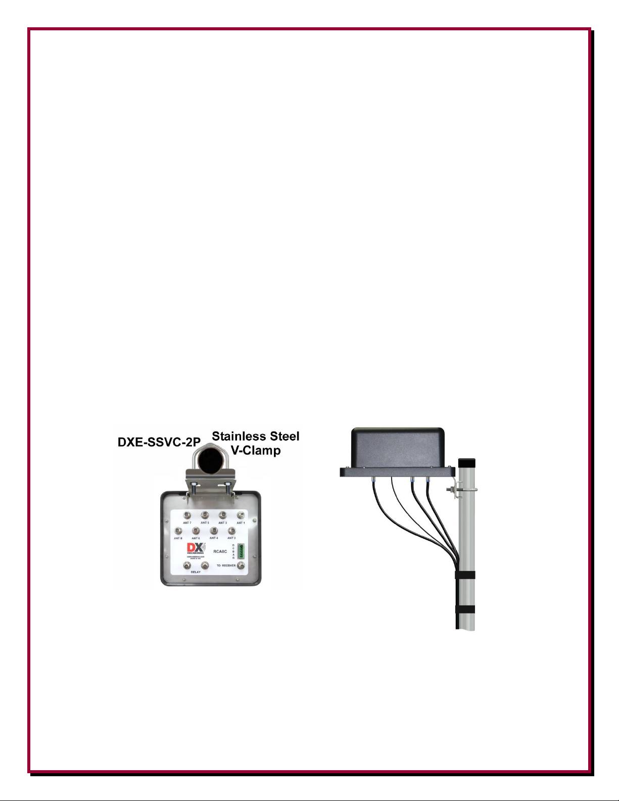
DXE-SSVC-2P Stainless Steel V-Clamp for mounting the RCA8C-1 Receive Eight Circle
Array Controller to a mounting post between 1" and 2" OD
Additional Parts Required, Not Supplied with the DXE-RCA8C-SYS-2P
DXE-CPT-659 Coaxial Cable Prep Tool for RG6, F6 75Ω Coaxial Cable, w/extra blade
DXE-SNS-CT1 Snap-N-Seal® Crimp Tool for 75Ω coaxial cable
DXE-SNS6-25 Package of 25 Snap-N-Seal® Connectors for 75Ω F6 coaxial cable
Five-Conductor Power and Control Cable - DXE-CW9S CAT5e may be used
DXE-6UF-1000 75Ω Coaxial Cable or equivalent
Eight identical Vertical Antenna Elements
Eight Circle Layout
The array optimized for single band performance has antenna elements are arranged in a circle with
a radius of about 175 feet for 160 meters, or 84 feet for 80 meters, or 44 feet for 40 meters. See the
Theory Of Operation sections and for exact dimensions and
guidance in choosing the best orientation.
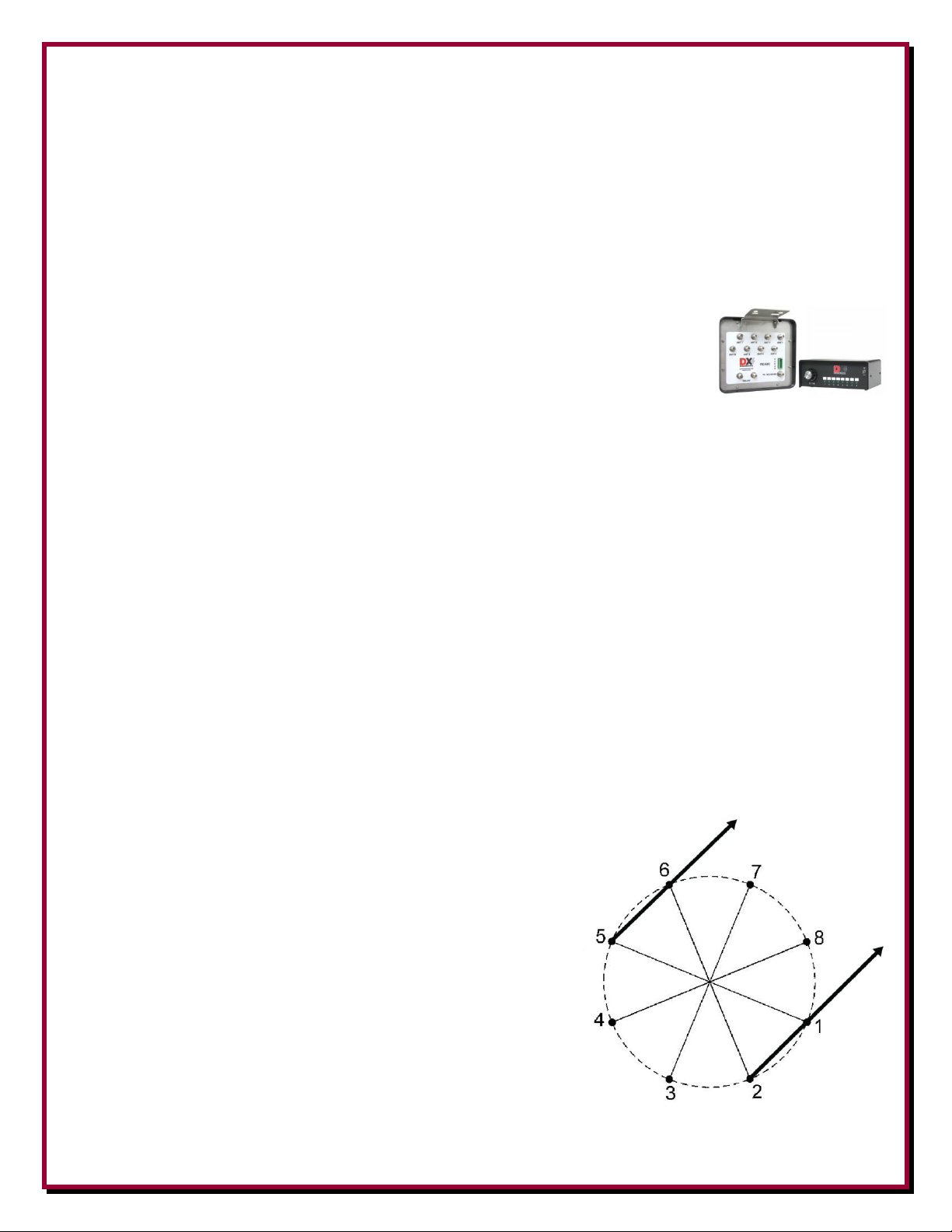
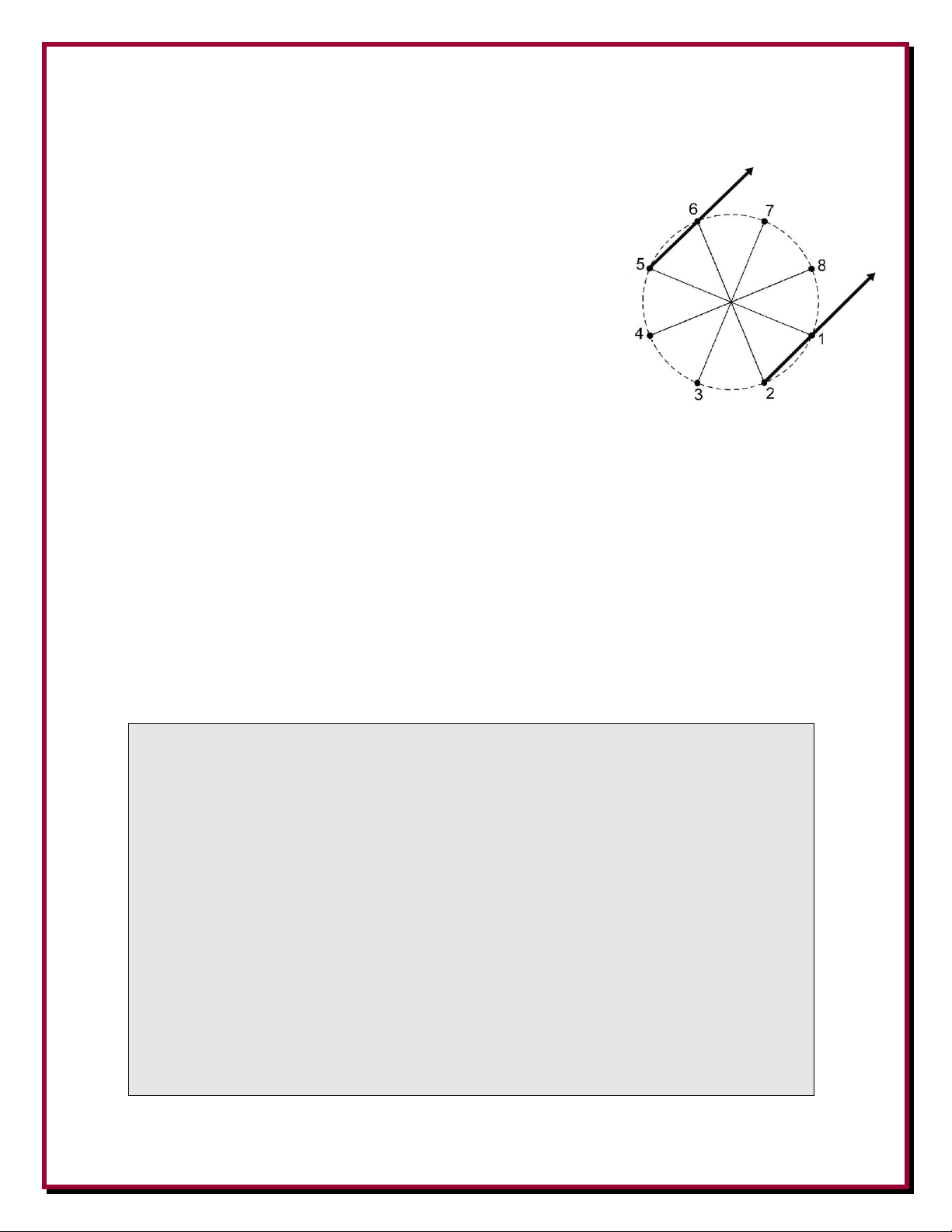
The default direction of the array with no voltage (BCD 000)
places elements 1 and 6 in front and elements 2 and 5 at the
rear, with pairs of lines through two opposite vertical element
pairs (tangents) that point toward the receiving directions.
Elements 1, 2 and 5, 6 are selected as the default for a
forward direction of North-East for North America, with
elements installed as shown. A mirror image of this element
positioning would be a typical default North-West for
European installations.
- 4 -
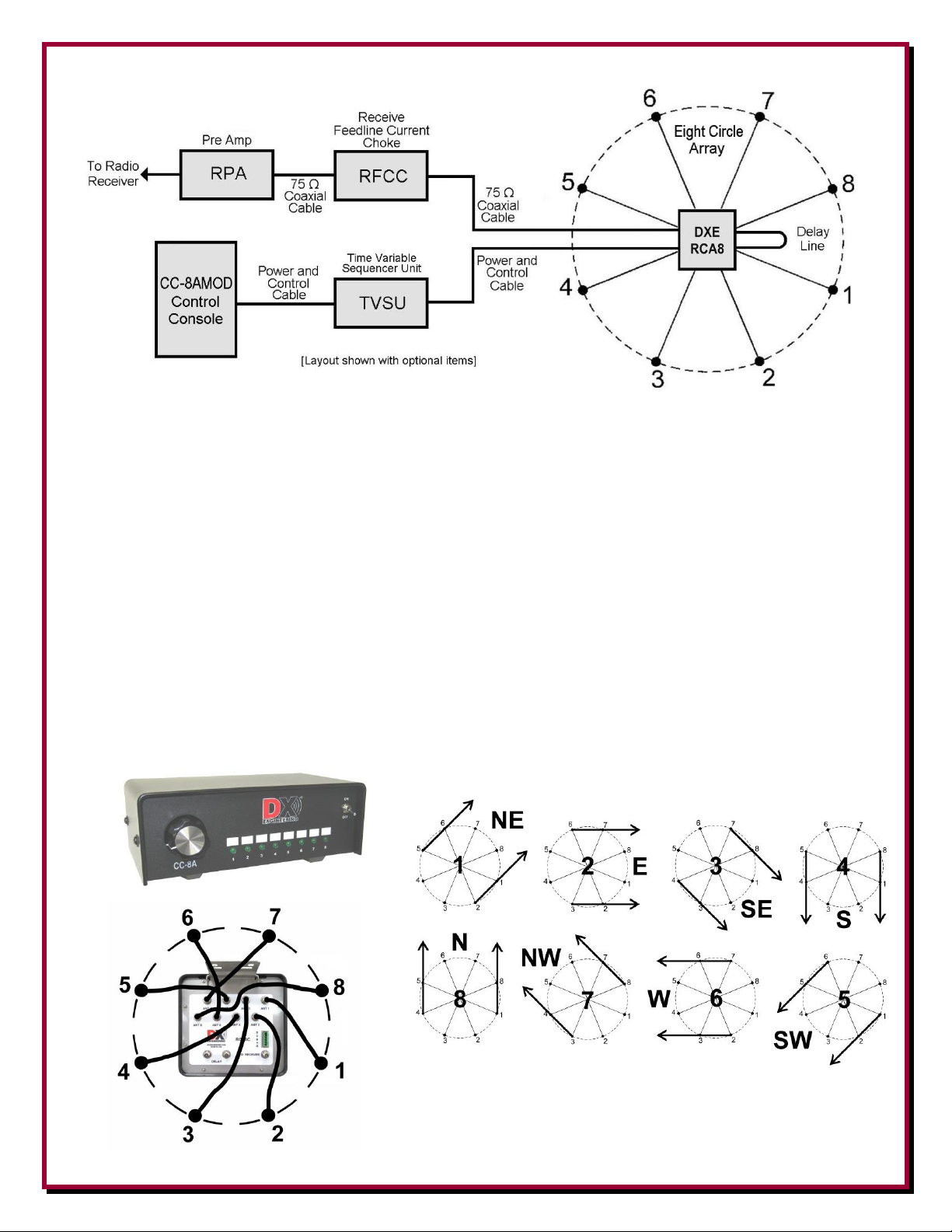
Figure 1 - Typical Diagram of the DXE-RCA8C-SYS-2P Receive Eight Circle Array System
System Overview
The heart of the DXE-RCA8C-SYS-2P system is comprised of the modified DXE-CC-8A Eight
Position Control Console and the RCA8C-1 Receive Eight Circle Array Controller. These units
interconnect and work together using factory default settings to control the Receive Eight Circle
Array. The modified CC-8A control console uses BCD switching voltages for the RCA8C-1 to
change the receiving direction of the array.
When the modified CC-8A Eight Circle Control Console and the RCA8C-1 Receive Eight Circle
Array Controller are connected as shown in the installation section below and the layout is as
described for North America in Figure 1, the switch positions on the modified CC-8A will switch
the array in the eight directions as shown in Figure 2.
Figure 2
- 5 -
Installation
The RCA8C-1 Receive Eight Circle Array Controller can be mounted to a customer supplied
galvanized steel pipe driven into the ground at the center of the array. A galvanized pipe ranging
from 1 inch OD to 2 inches OD may be used. The length of the controller unit's mounting pipe is
dependant on your location. The standard 1-1/2" galvanized water pipe (with its 1.9" OD) is just
fine for this application and can usually be found at your local home building supply store.
The RCA8C-1 relay unit has been pre-drilled to accommodate up to a 2 inch OD pipe using an
appropriate clamp. The included DXE-SSVC-2P Stainless Steel V-Bolt Saddle Clamp is for 1" to
2" OD pipe. An optional DXE-CAVS-1P V-Bolt Saddle clamp can be used for pipe from 3/4" to 13/4" inches OD. The controller can also be mounted on a sturdy wooden post if provision for
grounding the RCA8C-1 unit has been made. Note: JTL-12555 Jet-Lube SS-30 Anti-Seize should
be used on all clamps, bolts and stainless steel threaded hardware to prevent galling and to ensure
proper tightening.
The Receive Eight Circle Array Controller unit should be mounted as shown in Figure 3 with cover
upward and the control and coaxial cable connections downward to prevent water from entering the
box. The stainless steel base of the Receive Eight Circle Array Controller unit has weep holes to
allow condensation that may build up inside the unit to leave. Additional weatherproofing
protection can be provided when using the PTX-22058 Permatex Dielectric grease on all coaxial
connections. Dielectric grease is ideal for keeping moisture from entering your coaxial connectors.
It also acts as a lubricant allowing easy connector removal by stopping corrosion of electrical
connectors.
Figure 3 - RCA8C-1 unit mounted to 2" pipe using the included DXE-SSVC-2P V-Clamp
- 6 -
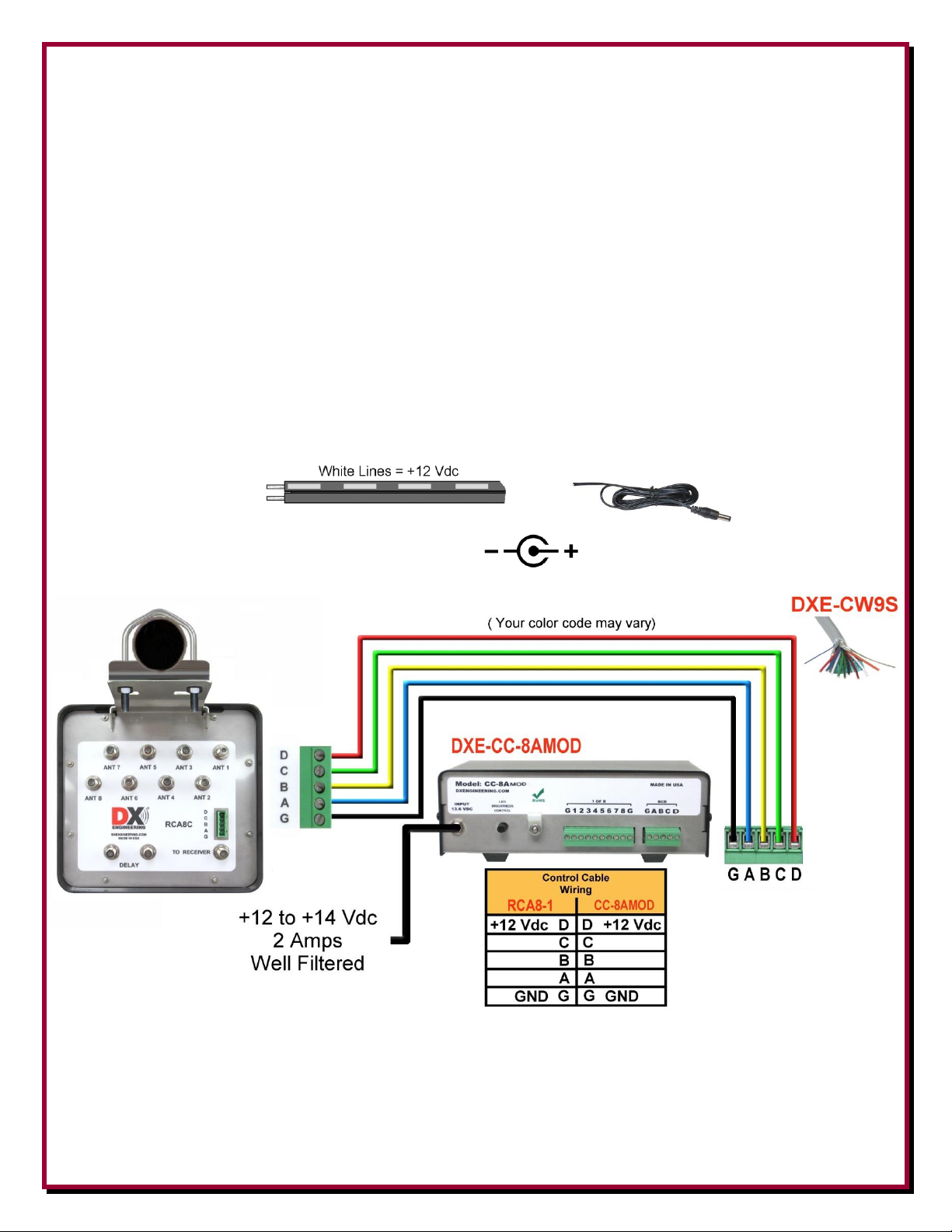
Control and Power Connections
1. Locate the removable green connector on the rear of the modified CC-8A labeled "G A B C D”.
The green connector is a two part connector as shown and the top part can be removed by
pulling it straight off. This will allow easier wire replacement or servicing as needed. When
pushing the removable connector back in place, ensure you press straight inward to fully seat
the connection.
2. Insert the five wire cable on the green connector as shown in Figure 4.
3. The same five wires are connected to the RCA8C-1 removable green connector (G A B C D) as
shown in Figure 5. (“D” is required only for voltage on the element feedlines and should not be
connected for passive vertical arrays.)
4. The modified CC-8A Control Console requires a nominal +12 Vdc fused input (+12 to +14
Vdc, 2 Amps and well filtered) through the 2.1 mm connector on the rear of the unit.
A 2.1 mm power cord is supplied with unit. The wire with the white stripes is the +12 Vdc.
Outer Connection is GROUND Center Pin is +12 VDC.
Figure 4
“D” is required only for voltage on the element feedlines and should not be connected for passive
vertical arrays.
- 7 -
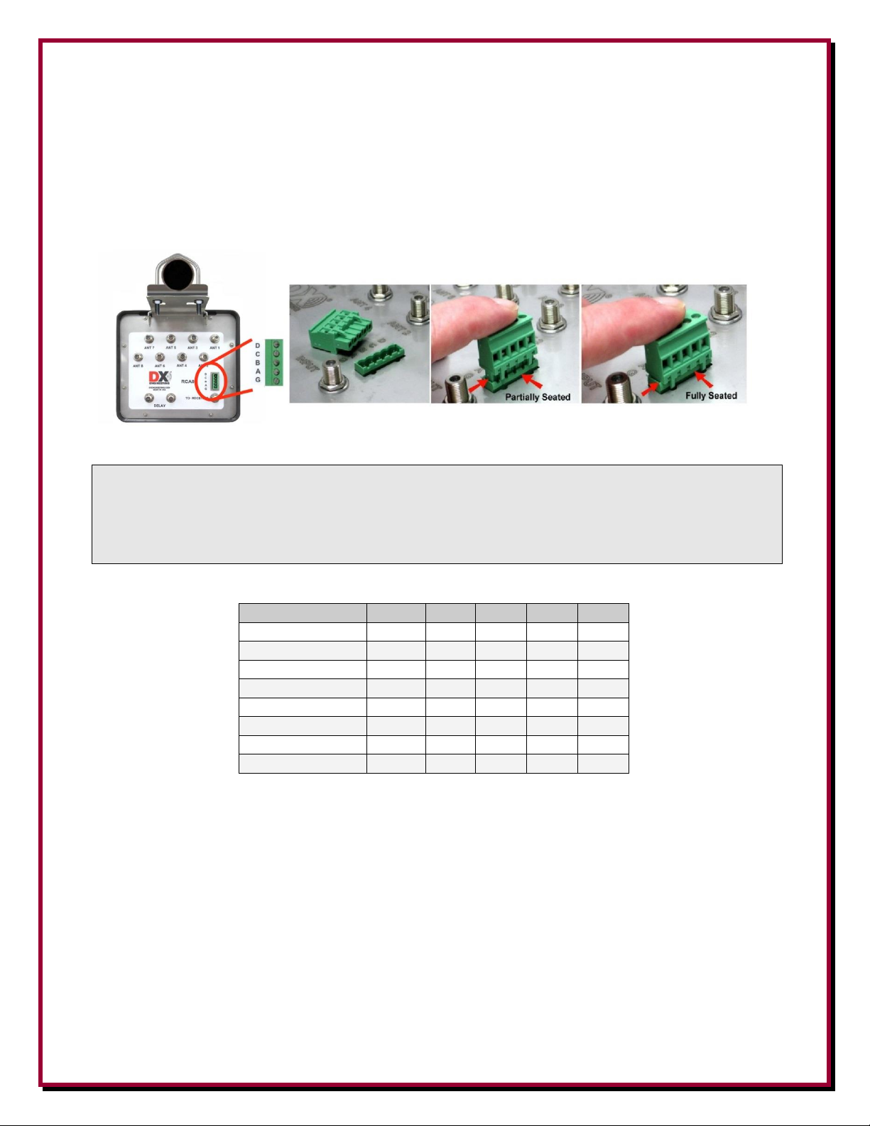
The RCA8C-1 uses a removable five terminal plug as shown in Figure 5. The RCA8C-1
NOTE: Since no voltage is required on the feedlines of mono-band passive vertical
elements, do not connect a voltage source to the “D” terminal on the RCA8C-1
connector.
Switch Position
G A B C D
1
GND
0 0 0 1 2
GND
1
0
0
1 3 GND
0 1 0 1 4
GND
1
1 0 1
5
GND
0
0
1
1
6
GND
1 0 1
1
7
GND
0
1 1 1
8
GND
1 1 1
1
connections are labeled “G A B C D”. The terminals use the same connection letters and are
connected G to G, A to A, B to B, C to C and D to D.
On the RCA8C-1 the green connector is a two part connector as shown in Figure 5 and the top part
can be removed by pulling it straight off. This will allow easier wire replacement or servicing as
needed. When pushing the removable connector back in place, ensure you press straight inward to
fully seat the connection.
Figure 5 - RCA8C-1 Green Connector
Table 1 - Modified DXE-CC-8A Output Truth Table
Control lines (usually BCD ) can normally use good quality CAT5e cable (4 twisted pairs of 24
AWG wire) for runs up to 1000 feet. Typical DX Engineering BCD control lines requirements are
+12 VDC at 25 milliamps.
Depending on the number of control lines needed (usually 3 or 4) you can double up the twisted
pairs of CAT5e cable, or use control wire that is at least 22 AWG, allowing runs up to 1500 feet. If
you use a cable with more conductors, it is a good idea to tie the unused conductors to ground.
- 8 -
For longer runs of control cable, use a line loss calculator to ensure you supply the proper control
Minimum Copper
Wire Gage (AWG)
Length
24
1,000 feet
22
1,500 feet
20
2,000 feet
Note: The DXE-RCA8C Eight Circle Receiving Array System should be separated from
transmitting or other antennas and structures (particularly metal) by at least 1/2wavelength. Less separation may cause significant pattern distortion and the
introduction of re-radiated noise into the system. This becomes apparent as reduced
front-to-rear directivity in one or more directions or a higher noise level.
levels needed.
Approximate BCD Control Line Lengths.
Receive Eight Circle Passive Vertical Elements
The DXE-RCA8C-SYS-2P Eight Circle Array is intended to be used with eight customer supplied
passive vertical elements designed for single band operation. Elements should be installed with
ground radials with their feedpoints as close to the ground as possible but above any standing water.
Your passive vertical elements must be identical and need to be constructed so that they are
resonant on your array band of choice. Their feedpoints must be matched to 75Ω coaxial cable in
order to match the DX Engineering RCA8C-1 system impedance of 75Ω. Short elements are
required to prevent mutual coupling and top loading with symmetrical capacity hat wires is
recommended to add electrical length.
It is important that the ground radial system is identical on each vertical element in the array.
Extensive details on the construction of the required passive elements are contained in “ON4UN’s
Low Band Dxing” by John Devoldere, available from DX Engineering.
Array Spacing
Performance of the Receive Eight Circle Array can noticeably decrease if structures radiating even
small amounts of noise or signals are within 1-wavelength of the array. There is no detrimental
effect when a higher frequency array of small receiving elements is placed inside the circle of a
lower frequency array of short elements.
With so many variables involved, there is no optimum or minimum spacing for effects on pattern.
The best practice is to install the array as far as possible from tall conductors or noise sources, or
- 9 -

place potential problems in less frequently used directions. For best pattern, space the system as far
as possible from conductors that might be noise sources or re-radiate unwanted signals. One
wavelength or more is generally ideal, although adequate performance generally occurs with much
smaller spacing, with one-half wavelength minimum recommended.
Typical DXE-RCA8C-SYS-2P Receive Eight Circle Configuration
Figure 6
Coaxial Cables are shown in various colors for clarity. Shown with optional DXE-RPA-2 Preamplifier,
optional DXE-RFCC Receive Feedline Current Choke
and optional DXE-CW9S Control Cable.
Power connection to the modified DXE-CC-8A Control Console is not shown.
- 10 -

Station Feedline, Active Antenna Feedline and Delay Line
The weakest link in an antenna system is often the coaxial cable connections. All connections must
be high quality and weather tight to prevent contamination and corrosion, which can cause the
feedline impedance to change. This can affect the signal-to-noise ratio and the directivity of the
array. If the coaxial cable is compromised the shield will then pick up unwanted signals. This is
why the shield connections are most critical. In addition, the DXE-RCA8C uses the shield as a
ground return path for the active element power.
All feedlines must be 75Ω and can be any length as long as they are all equal and they should come
from the same roll of cable so they have the same velocity factor (VF).
If the resistance of the shield increases due to contamination, the active elements may not function
properly. Any splices in the feedline should be high quality and entirely weather tight. Do not use
splices in the delay line cable. The DXE-RCA8C system has been designed to use only 75Ω coax.
High quality, flooded 75Ω CATV F6 type coax is recommended. The DXE-6UF-1000 flooded
cable automatically seals small accidental cuts or lacerations in the jacket. Flooded cable also
prevents shield contamination and can be direct-buried.
Feedline connections must have good integrity and be weather resistant. Highly recommended for
any DX Engineering array, and specifically designed for the DXE-6UF-1000 flooded cable is the
Snap-N-Seal® F connectors, model DXE-SNS6-25 which contains 25 connectors; enough for the
entire array plus spares. Snap-N-Seal® connectors cannot be installed with normal crimping tools or
pliers. The DXE-SNS-CT1 Compression Tool for Snap-N-Seal® 75Ω Coax Connectors is an
essential tool for proper connector installation.
Lightly coat threads of F connectors with pure clear non-hardening silicon dielectric compound,
such as PTX-22058 Permatex Dielectric Grease, to improve reliability of electrical connectors. This
will lubricate threads, seal connector threads from water ingress, and reduce chances of unwanted
bonding or welding of connector threads. If dielectric grease is not used, the potential for damage
to the various connectors may result and is not covered under warranty.
Note: DO NOT use pliers or other tools to excessively tighten the type F connectors; they
do not require high torque to make a good connection. F connectors are very
reliable strong connectors for their size, but carelessness can damage them.
Excessive tightening torque can loosen the chassis mounting-nut, allowing the
connector body to rotate and fracture the mounting tabs on either installation or
removal of the connector. F-connectors require modest torque, typically 6-12 inchpounds. 20-30 inch-pounds are FAR too high. That value, although commonly used,
is just wrong. Damage to the various connectors may result and is not covered
under warranty. Use a tool such as the DXE-CIT-1 F Connector Tightening Tool.
Additional weatherproofing protection can be provided when using the PTX-22058
Permatex Dielectric Grease on all coaxial connections. Dielectric grease is ideal for
keeping moisture from entering your coaxial connectors. It also acts as a lubricant
allowing easy connector removal by stopping corrosion of electrical connectors.
- 11 -

Vertical Element Feedlines
Use 75Ω coaxial cable from each antenna element to the RCA8C-1. The eight feedlines from the
RCA8C-1 to the elements can be any length needed to accommodate the size of the array, but must
all be the same physical length, velocity factor and type. Note the orientation and numbering of
the elements by using Figure 7. Be sure the appropriate antenna element is connected to the proper
ANT connector on the RCA8C-1. Additional weatherproofing protection can be provided when
using the PTX-22058 Permatex Dielectric grease on all coaxial connections. Dielectric grease is
ideal for keeping moisture from entering your coaxial connectors. It also acts as a lubricant
allowing easy connector removal by stopping corrosion of electrical connectors.
Figure 7 - Vertical Elements
Coaxial Connections
to the RCA8C-1
Delay Line
The DX Engineering DXE-RCA8C-1 uses a time delay system, not a traditional phasing system.
The delay line length is dictated by array dimensions rather than operating frequency, allowing for
the use of a single delay line for optimum directivity over a very wide frequency range. This results
in phase being correct for a rearward null at any frequency.
The DXE-RCA8C-1 unit has two delay line female F connectors marked DELAY. This connection
pair will require one specific length of a coaxial cable assembly with male F connectors acting as a
jumper between the two female F connectors. Delay line electrical length is critical. Careful
measurements and the use of 75Ω coaxial cable with a known Velocity Factor (VF) is very
important.
We strongly recommended the use of DX Engineering DXE-6UF-1000 High Quality, Low Loss,
75Ω F6 type Direct Bury Coax "Flooded" Coax. The DX Engineering DXE-6UF-1000 75Ω
coaxial cable has a nominal VF of 0.83. Keep in mind that solid Teflon® or polyethylene (PE)
dielectric coaxial cable has a VF of approximately 0.66. Foamed coaxial cable cables typically
range anywhere between 0.75 and 0.90 VF, depending on the ratio of air-to-dielectric material in
the cable core. If you do not know the VF of the coaxial cable you are using, you must directly
measure the electrical length of the coaxial cable you have with an analyzer or obtain cable with a
known VF.
- 12 -

For a single-band Eight Circle Array, the required electrical length of the delay line is based on the
Band Coverage
Desired
Optimal Eight
Circle Array
.327-wavelength
Radius in Feet
Adjacent Element
(Endfire Cell)
Quarter-
Wavelength
Physical Spacing in
Feet
Factored
0.95
Electrical
Length
in Feet
Delay Line
Physical
Length in
Feet
(0.83 VF)
160 meters only
(1.830 MHz)
175.64
134.43
127.71
106.00
80 meters only
(3.800 MHz)
84.58
64.74
61.50
51.05
40 meters only
(7.200 MHz)
44.66
34.17
32.46
26.94
distance between each of the two adjacent elements on the circle. As shown in Table 2, the
calculation of the electrical length of the delay line is 95% of the physical distance between adjacent
elements or adjacent element distance times 0.95 for a single band or multiple band array. The
electrical length is then multiplied by the VF of the coaxial cable being used to determining the
correct physical length of the delay line. The result is the correct physical length for the Delay Line
in the right column of Table 2.
Note: These calculations are in decimal feet, not feet and inches.
Table 2 shows delay line length calculations based on the dimensions for the three most common
bands for a Receive Eight Circle Array.
For Example: An Eight Circle Array intended to be optimized for 160 meter only operation has
The correct physical length for this delay line is 106 feet.
The delay line cable can be neatly coiled in a 1-1/2 ft diameter coil. Support the weight of the coiled
cable by taping or securing it to the support pole or mast rather than allowing it to hang from the
connectors.
It is important to use 75Ω feedline to the operating position from the DXE-RCA8C-1 unit. Do not
use amplifiers, combiners, filters or splitters that are not optimized for 75Ω systems.
Lightning Protection
While amateur radio installations rarely suffer damage from lightning, the best protection is to
disconnect electrical devices during storms. The key to lightning survival is to properly ground
Table 2 - Specific Delay Line Length Calculations for single band arrays.
an optimized .327-wavelength radius dimension of 175.64 feet, and Endfire Cell
adjacent element spacing of 134.43 feet. The 0.95 factored electrical length is
127.71 feet. Multiply 127.71 by 0.83 (the VF of DX Engineering 75Ω coaxial
cable) to determine the physical length of the delay line.
- 13 -

feedlines and equipment and to maintain the integrity of shield connections. A proper installation
improves lightning protection and enhances weak signal receiving performance.
Consult lightning protection and station grounding information in the ARRL handbooks, or by
referring to the NEC (National Electric Code). The DX Engineering website has technical and
product information listed under “Lightning Protection and Grounding”. Use lightning surge
protectors for the coax feedline and control lines such as the DXE-RLP-75FF Lightning Protector,
Receive 75Ω, DC Pass, with F Connectors, for the array feedline at the station end ground.
Optimizing the Array
To determine if the antenna system output level is the limiting factor, tune the receiver to the lowest
band at the quietest operating time. This is usually when propagation is poor but some signals are
heard. Disconnect the antenna and set the receiver to the narrowest selectivity you expect to use.
Receiver noise power is directly proportional to receiver bandwidth (going from 2.5 kHz selectivity
to 250 Hz selectivity reduces noise by 10 dB). Connecting the antenna should result in a noticeable
increase in noise. If so, the array signal level is sufficient and further optimization or amplification
may not be needed.
If the array is used on 160m, and the array still lacks sensitivity on 160 meters, then a preamplifier
with high dynamic range should be used to compensate for the low signal level. Using a preamplifier when sufficient signal is already present may result in amplification of the noise along
with the signal. It is always best to use the least gain possible. Depending on conditions, a
preamplifier can cause receiver overload; this may require an attenuator or bypassing the
preamplifier. The DXE-RPA-2 HF Preamplifier has better dynamic range than most receivers and
can be used to compensate for the decrease in array signal output.
Theory of Operation of the Eight Circle Array
The following Sections contain specific information about the fundamentals of the Eight Circle
Array. It contains all of the information needed to make decisions about the band coverage desired,
and how band coverage is affected by the selection of the optimal pattern in relation to the circle
radius. Also included is information discussing the differences between the use of passive or active
vertical elements.
System Design Features and Benefits
The DX Engineering Receive Eight Circle Array is the highly sophisticated receive eight circle
system that uses time delay phasing - rather than the conventional narrow-band, frequency
dependent phasing - to provide eight 45 degree spaced directional patterns. The time delay phasing
is directivity-optimized to produce wider and deeper rear nulls and a narrower main lobe. The result
is that noise and undesirable signals are greatly reduced by superior front-to-rear (F/R). The array
forms a clean stable pattern with high directivity over wide bandwidth.
- 14 -
W8JI initially developed and used this array in the 1980’s. This array started appearing in the
1990’s at larger more advanced low-band DX stations. The phasing system in this array, as
well as the active element design, offer much better dynamic range and directivity bandwidth
than other later copies.
Unlike unidirectional transmitting arrays using large elements, very small
elements do not create significant mutual coupling related currentdistribution and phase errors. Better control of phase and currents provides a
much cleaner pattern than found on available vertical antenna transmit
arrays.
Additionally, this array combines independent unidirectional cells across the
full width of the array to add additional broadside directivity. Broadside
phasing is also frequency independent.
Time-delay phasing produces a frequency independent rearward null.
Phasing remains perfect over very wide frequency ranges. This results in excellent front-to-back
performance on multiple bands, despite using a single delay line with fixed element spacing. The
deep rearward null reduces rearward noise and undesirable signals over very wide frequency ranges.
The rearward null is frequency independent up to element-to-element spacings of just over 1/4wavelength.
The DX Engineering RCA8C-1 Receive Eight Circle Array Controller uses sealed relays sized for
receiving applications. (High current contacts, suitable for transmitting, commonly have unreliable
contact connections at low currents. This is because of the large surface areas and hard contact
materials necessary to support high contact switching currents.) The RCA8C-1 Receive Eight
Circle Array Controller uses sealed relays optimally sized for receiving applications. Contacts are
bifurcated and gold-flashed, substantially improving low signal level switching reliability. The
improved low-level signal optimized bifurcated contacts virtually eliminate non-linearity,
rectification, and other maladies caused by poor relay connections.
Frequency Coverage -vs. - Element Type
The Eight Circle Array uses eight elements to form a clean, narrow beamwidth, low-angle pattern in
eight equally spaced user selectable directions. The elements form the most space-efficient type of
directional array, a broadside-endfire combination. With broadband active elements, this array has
an exceptionally good pattern over at least a 3:1 frequency range. With monoband passive resistor
loaded elements, this array has unbeatable performance across a single band.
The Eight Circle Array upper frequency limit for a clean unidirectional pattern is slightly above
where the array is .35-wavelength radius. The frequency of optimum performance is where the
array is approximately .327-wavelength radius. Construction care, element construction, desired
beamwidth, and local noise floor determines the minimum array size in wavelengths. Minimum
useful frequency typically occurs with an array less than 0.1-wavelength radius; although that limit
can be pushed lower with care in some situations. Careful construction will allow useful directivity
over the entire HF range with an exceptionally good pattern over a 3:1 frequency range.
- 15 -
A Special Application
The DX Engineering DXE-RCA8C Eight Circle Array phasing and switching system may
also be used as a unidirectional or bidirectional end-fire/broadside array with the installation
of only four vertical elements, using 1/10 to 1/4-wavelength endfire spacing in combination
with 1/4 to 3/4-wavelength broadside spacing.
This limited implementation is for the user who specifically wants a very directional receive
antenna system that is pointed only in one direction, without power required, similar to a
single direction, phased Beverage array. It would also be switchable to a second opposite
direction with DC power, similar to a very long Reversible Beverage.
However, this end-fire/broadside array alternative to building a phased Beverage array
requires a lot less space and a lot less maintenance! Contact DX Engineering for more details
on the use of the DXE-RCA8C for a four element system.
Receive Antennas – Gain and Efficiency
One popular misconception is that antenna gain pays equal dividends in receiving and transmitting.
While transmit to receive antenna gain reciprocity applies to changes in absolute signal levels, it
does not apply to signal-to-noise. Once external noise levels are slightly above receiver noise floor,
signal-to-noise ratio is almost entirely a function of antenna pattern. System loss or system gain is
no longer a factor, and excessive gain can actually hurt reception of weak signals.
Efficiency is not a major consideration in dedicated receiving systems. This allows application of
techniques that increase directivity in receive-only systems, techniques generally unworkable or
unacceptable in transmitting antennas. In a Multi-Multi contest station environment, passive receive
elements offer significantly greater dynamic range.
Site Selection
Site selection is important. Three major things upset the pattern and performance of an array. Phase
errors, element impedance errors, and improper spacing. This array’s phasing system uses a
combination of end-fire and broadside phasing. This array forms a clean stable pattern with high
directivity over wide bandwidth. Because of the stable, clean, narrow pattern in eight selectable
directions, this antenna is the ultimate in receiving.
Directing the antenna pattern away from noise sources or toward the desired signal path is the
primary benefit. Antenna gain is a secondary advantage. As frequency increases, the fixed array size
becomes electrically larger in terms of wavelength. The increased electrical spacing produces higher
sensitivity (average gain) even though front-to-rear ratio only changes slightly. On the low bands,
- 16 -
once the receiving system, including the antenna system and the receiver, are hearing the lowest
Note: The DXE-RCA8C Eight Circle Receiving Array System should be separated
from transmitting or other antennas and structures (particularly metal) by at least
1/2-wavelength. Less separation may cause significant pattern distortion and the
introduction of re-radiated noise into the system. This becomes apparent as
reduced front-to-rear directivity in one or more directions or a higher noise level.
With so many variables involved, there is no optimum or minimum spacing for
effects on pattern. The best practice is to install the array as far as possible from
tall conductors or noise sources, or place potential problems in less frequently
used directions. For best pattern, space the system as far as possible from
conductors that might be noise sources or re-radiate unwanted signals. One
wavelength or more is generally ideal, although adequate performance generally
occurs with much smaller spacing.
There is no detrimental effect when a higher frequency array of small receiving
elements is placed inside the circle of a lower frequency array of short elements.
possible level of local and propagated ambient noise, antenna directivity (F/R) is the only thing that
affects the signal-to-noise ratio.
The default direction of the array with no voltage (BCD 000) places
elements 1 and 6 in front and elements 2 and 5 at the rear. Pairs of
lines through two opposite vertical element pairs (tangents) point
toward the receiving directions. Elements 1, 2 and 5, 6 are selected
as the default, for a forward direction of North-East, with elements
installed as shown for North America. A mirror image of this
element positioning would be a typical default direction of NorthWest for European installations.
This array can use active or passive elements. Passive elements provide the greatest dynamic range
and immunity to overload. Active elements provide the widest system bandwidth, but at the expense
of dynamic range.
Receiving antennas work best when they have a clean pattern with narrowest possible lobe, and
minimal spurious lobes. This is because noise generally comes from many directions, while a signal
comes from one useful direction at a time. If a signal comes from multiple angles or directions we
still do not want those directions, because the phase relationship and levels of the multiple path
single source signal will vary a great deal. This will cause undesirable fading and distortion. We
cannot successfully directly mix multiple antennas for diversity reception for the same reasons we
do not want an antenna to respond to the same signal source over multiple paths, since we cannot
combine randomly varying phase and level signals without increasing fading or reducing signal-tonoise (S/N) ratio.
- 17 -

Effects On Pattern
As far as pattern goes every directional array, no matter how constructed or designed, will always
interact with surrounding conductors. Adequate spacing is almost entirely dependent on electrical
characteristics of the surrounding conductors for a given style of receiving array.
For example, a given style array of similar dimensions from one company will be similarly affected
by surrounding conductors regardless of element design, for a given style of element. The effect on
pattern depends almost entirely on how much surrounding objects absorb and re-radiate signals, if
the undesired structure is in a null or peak of the receiving array, and how close the systems are in
terms of wavelength.
With so many variables involved, there is no optimum or minimum spacing for effects on pattern.
The best practice is to install the array as far as possible from tall conductors or noise sources, or
place potential problems in less frequently used directions. For best pattern, space the system as far
as possible from conductors that might be noise sources or re-radiate unwanted signals. One
wavelength or more is generally ideal, although adequate performance generally occurs with much
smaller spacing.
Site Selection in Relation to Noise Sources
Because the array is directional, use this example as a guide: If you have a noise source and if your
primary listening area is northeast, locate the array northeast of the dominant noise source. This
ensures the array is looking away from the source of noise when beaming in the primary listening
direction. The second-best location for the array is when the noise source is as far as possible from
either side of the array. If you look at patterns, the ideal location for the array is one that places
undesired noise in a deep null area. If this receiving array is in an area free of noise sources (power
lines, electric fences, etc.), locate the array so transmitting antennas and buildings are located in a
null direction or commonly unused direction.
Noise that limits the ability to hear a weak signal on the lower bands is generally a mixture of local
ground wave and ionosphere propagated noise sources. Some installations suffer from a dominant
noise source located close to the antennas. Noise level differences between urban and rural locations
can be more than 30 dB during the daytime on 160 meters. Nighttime can bring a dramatic increase
in the overall noise level as noise propagates via the ionosphere from multiple distant sources. Since
the noise is external to the antenna, directivity can reduce noise intensity.
Consider these things about noise sources:
If noise is not evenly distributed, performance will depend on the gain difference between
the desired signal direction (azimuth and elevation) and gain in the direction of noise.
If very strong noise comes from the direction of a receiving antenna null, improvement in
S/N ratio can be as much as 30 dB or more
If noise predominantly arrives from the direction and angle of desired signals (assuming
polarization of signals and noise are the same) there will be no improvement in the signal-tonoise ratio.
- 18 -
If the noise originates in the near-field of the antenna, everything becomes unpredictable. This is a
Band
Unity (0 dB) Gain
3 dB Gain (2x)
6 dB Gain (4x)
160m (1.8 MHz)
55 ft
110 ft
220 ft
80m (3.5 MHz)
28 ft
56 ft
112 ft
40m (7.0 MHz)
15 ft
30 ft
60 ft
good case for placing receiving antennas as far from noise sources (such as power lines) as possible.
Proximity to Transmitting Antennas
The ability of passive vertical element matching system components to survive high RF fields
depends on component ratings.
The DX Engineering Active Matching Units with customer supplied vertical elements, or the DXE-
ARAV4-8P Receive Antenna Active Vertical with Relay active elements and your transmitting
antenna need only minimal physical separation to maintain safe power levels when the optional
DXE-TVSU-1B Time Variable Sequencer Unit is used. With 1500 watts output and a unity gain (0
dB) antenna, the closest active element can be 1/10-wavelength from the transmitting antenna at the
lowest transmitting frequency. Doubling the protection distance quadruples safe power levels. See
Table 3.
Table 3 - Array Safety Distance Minimums at 1500 watts
Table 3 indicates minimum safe distances for the sequenced active array from transmitting antennas
with 0 dB, 3 dB and 6 dB gain (ERP) using a 1500 watt transmitter. Your actual system may vary
according to location and proximity to various objects. Your actual system may vary. Safe distance
will vary depending on operating frequency, antenna polarization and orientation, and
transmitting antenna pattern.
- 19 -
Examples of Array Performance
The DXE-RCA8C eight circle array system occupies less space than phased Beverage arrays and is
much easier to install, is less conspicuous and operates over a wider frequency range with similar or
better performance.
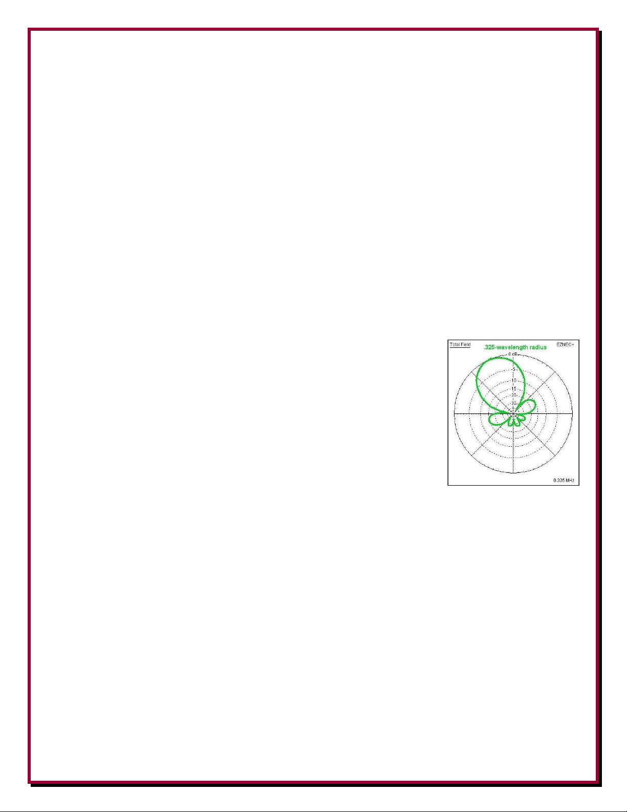
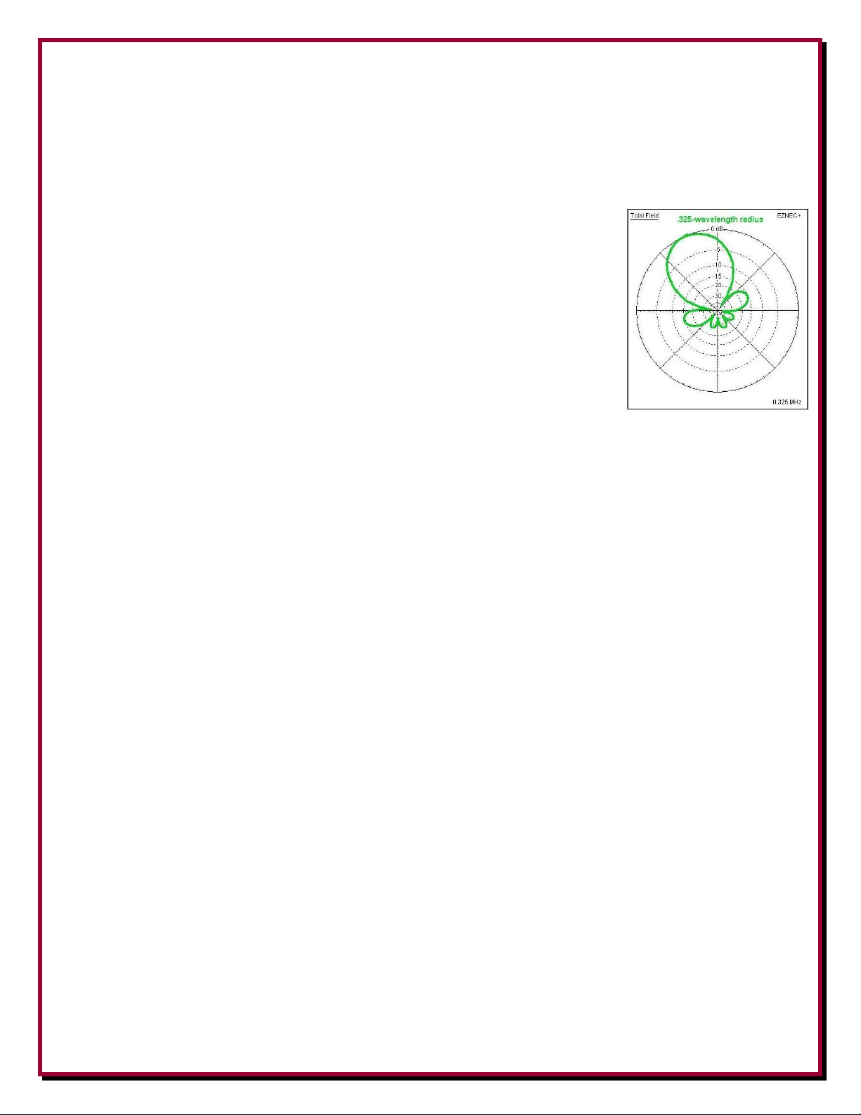
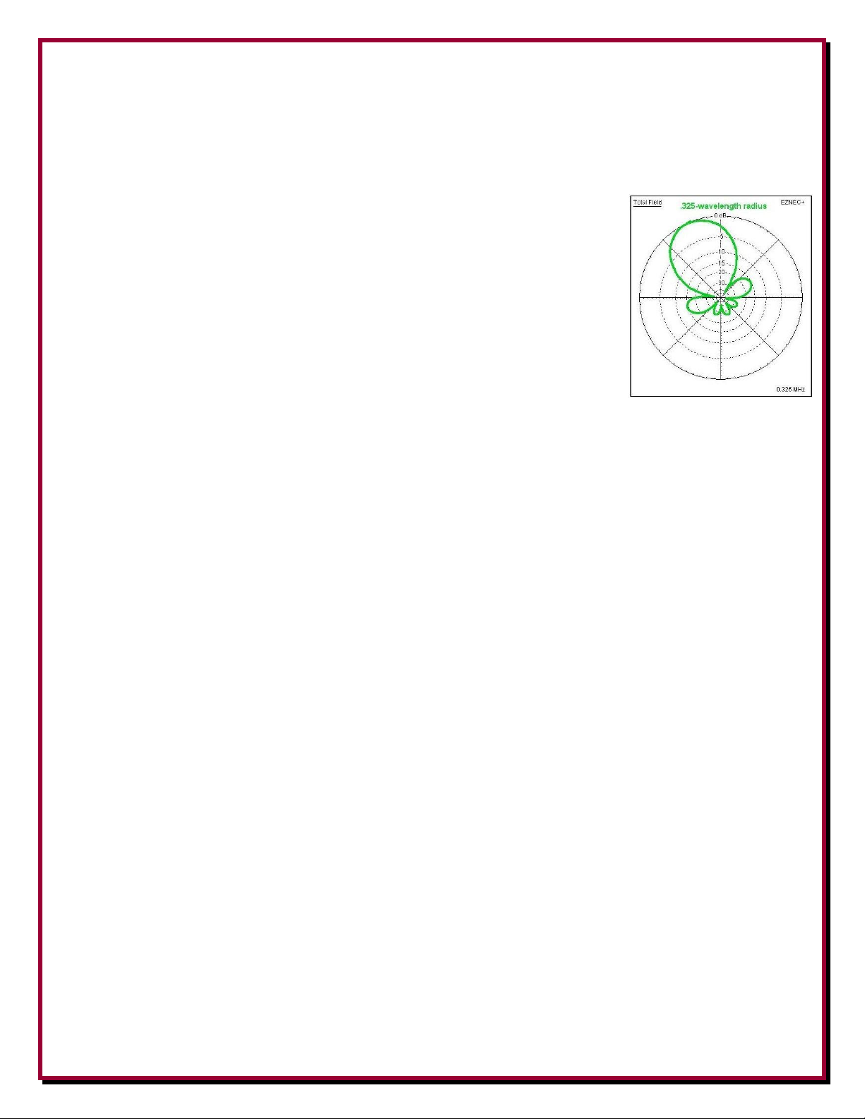
The Eight Circle Array achieves an optimal pattern when the array has a
radius of .327-wavelength. This is represented by this azimuth pattern in
labeled as “.325-wavelength radius”, which shows the best combination of a
narrow front lobe and acceptable side lobes. This pattern is true for any
frequency from 500 kHz to 30 MHz. This pattern achieves the best
Receiving Directivity Factor (RDF), which is a figure that compares the
forward-lobe gain to the average gain of the antenna array in all directions,
including azimuth and elevation. More information about the rating of
receive antenna systems and Receive Directivity Factor are described in
“ON4UN’s Low Band Dxing” by John Devoldere, available from DX
Engineering (DX Engineering part number: ARR-8560).
As shown by the patterns of Figure 9, an optimized 160 meter Eight Circle Array is not useable on
80 meters. That is why the best performing Receive Eight Circle is built as a mono-band array.
The ultimate low band receiving antenna would be two Eight Circle Arrays, one optimized for 80
meters built inside of the other optimized for 160 meters. Each is optimally sized for a .327wavelength radius, according to the dimensions in Table 4.
The DX Engineering Eight Circle Array offers better directivity than the Receive Four
Square. However, it requires more real estate to accomplish better directivity, which in turn
requires eight selectable directions to cover all directions properly.
Only a monoband array may be installed with passive verticals or active vertical elements, but a
multi-band Eight Circle Array must be installed with Active Vertical elements.
Multi-Band Arrays with Active Elements
Only the DX Engineering Active Receive Verticals or Active Matching Units with constant 75Ω
impedance and unsurpassed dynamic range across the frequency range will allow this Eight Circle
Array coverage. See the manual for the DXE-RCA8C-SYS-4S Complete Eight Circle Array
System Package.
Considering the available patterns from the Eight Circle Array, the best possible choice for a twoband array covering 80 and 160 meters is one that is optimized for 80 meters. The resulting patterns
are represented closely to the patterns in Figure 9 by the “.325-wavelength radius” for 80 meters
and by the “.15-wavelength radius” for 160 meters, with a narrower pattern and performance
exceeding short Beverage arrays.
- 20 -
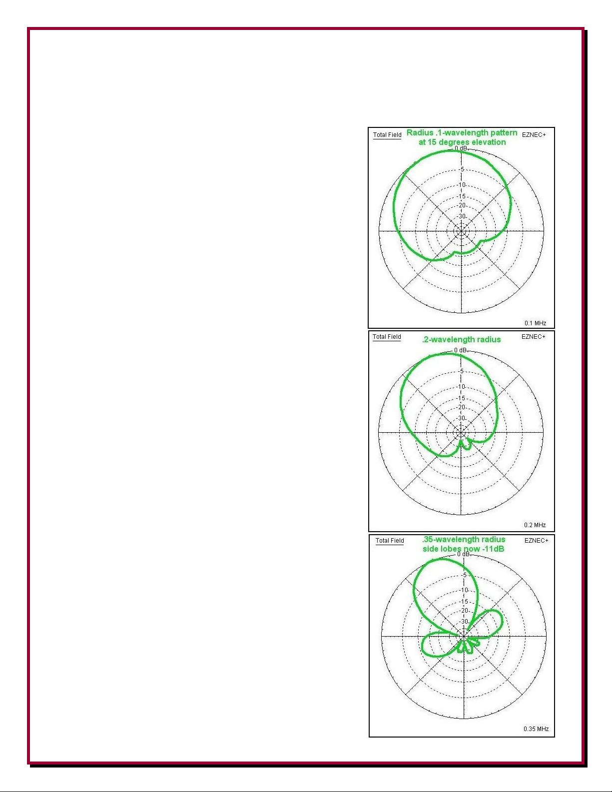
The absolute maximum useful directional frequency coverage of the Eight Circle Array is about a
4:1 ratio. A compromise Eight Circle Array System should be sized with its highest frequency
corresponding to an array radius of .375-wavelength, being limited by allowable side lobe levels, as
shown in Figure 9.
For example, an array built to cover 160, 80 and 40 meters
has the highest frequency of 7.3 MHz will have a .375wavelength radius of about 50.5 feet, which offers excellent
rear rejection on 40 meters, a respectable cardioid pattern on
80 meters, and still offer useable directivity on 160 meters.
The patterns on these bands are represented in Figure 8 by
“.375-wavelength radius” for 40 meters, just about the same
as the “.2-wavelength radius” pattern on 80 meters and the
“.1-wavelength radius” pattern for 160 meters.
An array sized for the highest frequency of 2.0 MHz with a
.375-wavelength radius of 184.43 feet, would provide the
best pattern (.327-wavelength radius) at 1.744 MHz, but still
offer good directional performance down to 500 kHz. An
array sized for the highest frequency of 21.5 MHz with a
.375-wavelength radius of 17.16 feet, would provide usable
directivity down to 5.3 MHz.
NOTE: An array which is intended to be used over a
frequency range greater than 3:1 requires a different Delay
Line than one intended for a single or two-band system. See
the manual for the DXE-RCA8C-SYS-4S Complete Eight
Circle Array System for details.
Figure 8
- 21 -
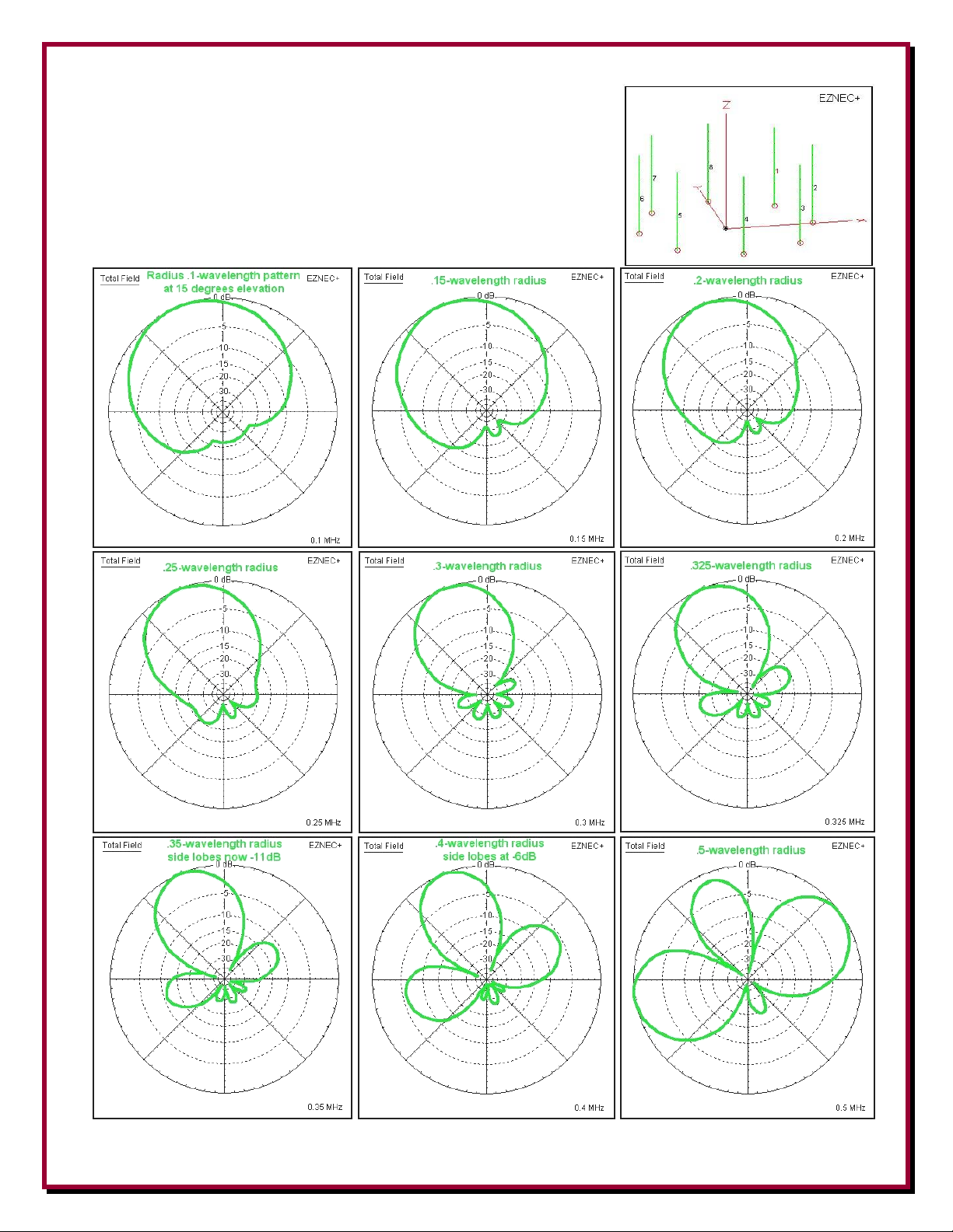
The azimuth patterns in Figure 9 were generated using EZNEC+
and show the effects on the patterns when varying the radius of the
array. These patterns are not to be viewed as pointing in a default
or particular direction.
Figure 9
- 22 -

Topographical Considerations
Flat land is best. Erecting the receiving array on sloped land or steep hills may degrade
performance. To avoid pattern degradation, antenna elements must have reasonably similar
elevations. It's recommended the ground height difference between any element in the array be less
than 10% of the array diameter. For example, a 100 foot diameter array should be within ten feet of
level. Every effort should be taken to make the elements symmetrical. Elements should all be
identical in construction and grounding, and should be mounted above any potential standing water
line but as close to the ground as possible. In general, the system will not be affected by trees or
foliage as long as the foliage does not contact the element. Ideally, in important receiving
directions, there should be a clear electrical path for at least 1-wavelength. The site should allow a
ground system to be evenly distributed around each antenna, if one is required, as for passive
elements.
Sizing the Array
If there are no space constraints, follow the dimensional recommendations in Table 4 for excellent
performance.
Only a monoband array may be installed with passive verticals or Active Vertical elements,
but a multi-band Eight Circle Array must be installed with Active Vertical elements.
An Eight Circle Array that is optimized for a certain band will not yield useful results on the next
higher frequency band. If you are using the Active Receive Verticals so that you can obtain
directional receiving performance on two or more bands, the array must be sized for the highest
frequency band. The Active Receive Vertical elements provide the required 75Ω impedance across
multiple bands in order to maintain pattern stability.
A monoband 160 meter optimized Eight Circle Array is sized by multiplying the free space
wavelength at 1.832 MHz of 537 feet/wavelength times the optimum pattern circle radius of 0.327
wavelengths, which yields an optimal circle radius of 175.6 feet. This places the vertical elements
about one-quarter wavelength apart, 134.25 feet.
However, as shown by the patterns of Figure 9, an optimized 160 meter Eight Circle Array is not
useable on 80 meters.
If the Eight Circle Array is intended to be used monoband on 80 meter, or if it will be used on 80
and 160 meters, then the best choice for sizing the array is shown at the bottom of Table 4. This is
where the free space wavelength at 3.803 MHz of 258.65 feet/wavelength is multiplied by the
optimum pattern circle radius of 0.327 wavelengths, which yields an optimal circle radius of 84.58
feet. This places the vertical elements about one-quarter wavelength apart, 64.74 feet.
- 23 -

Endfire
Spacing
Radius of Circle
Broadside
Spacing
Freq
MHz
Distance
Between
Antennas =
246/F [feet]
One Half
Distance
Between
Antennas
[feet]
Radius of
Circle[feet] = 1/2
distance between
antennas divided by
sin 22.5 degrees
(0.383)
Diameters
of Circles
[feet]
Diameter,
Endfire
Spacing &
Broadside
Spacing
form a
triangle.
Broadside
Spacing as
a % of WL
1.800
136.67
68.33
178.6
357.1
329.9
0.604
1.825
134.79
67.40
176.1
352.2
325.4
0.604
1.830
134.43
67.21
175.64
351.3
324.5
0.604
1.860
132.26
66.13
172.8
345.6
319.3
0.604
3.500
70.29
35.14
91.8
183.7
169.7
0.604
3.650
67.40
33.70
88.1
176.1
162.7
0.604
3.800
64.74
32.37
84.58
169.2
156.3
0.604
7.200
34.17
17.09
44.66
89.32
82.5
0.604
Antennas are spaced 45 degrees apart. Layout above is typical for North America with the
default position (1) having the array point toward the North East.
Table 4 - Array Dimensional Layout (Highlighted figures are optimal for 1.83, 3.8 and 7.3 MHz)
- 24 -
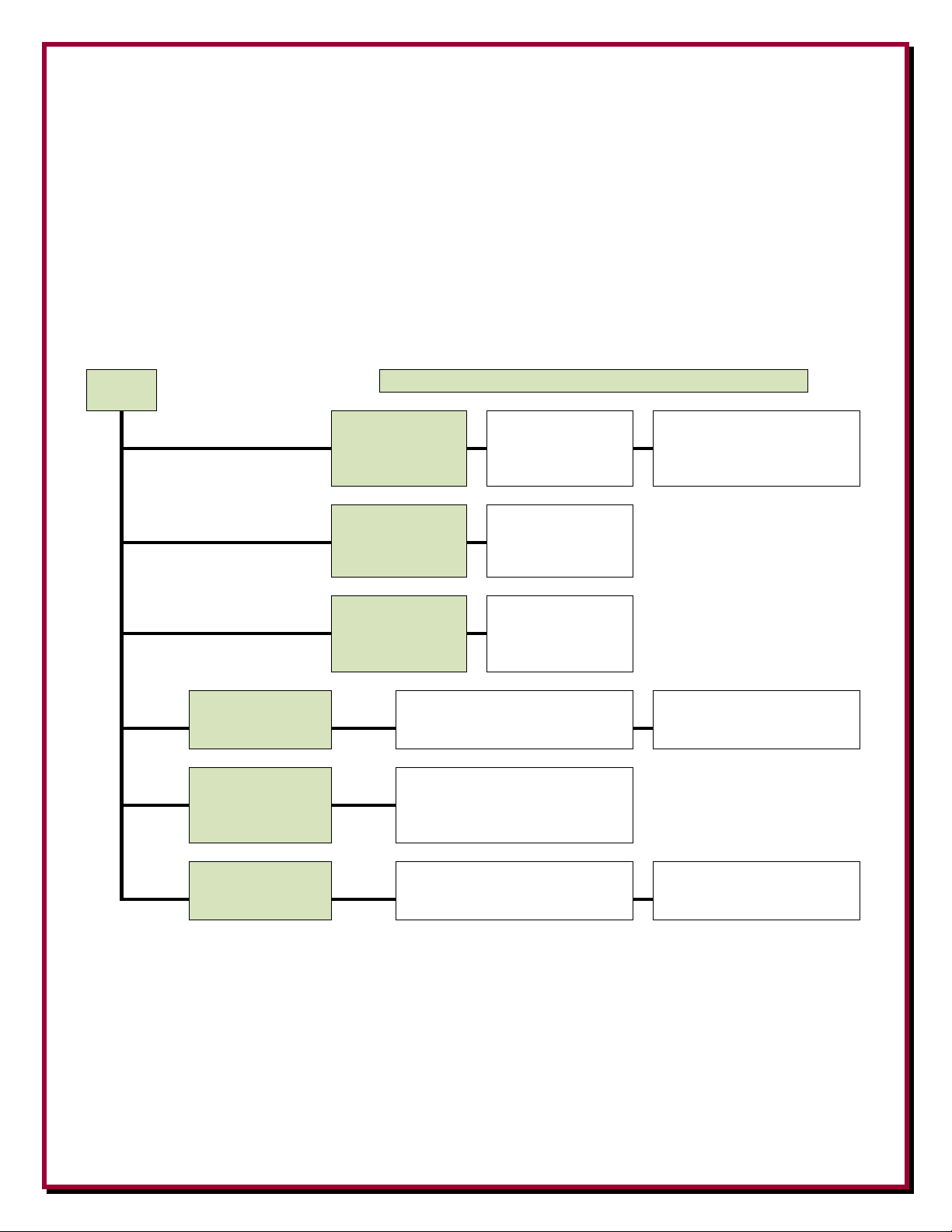
Receive Eight Circle Troubleshooting
START
80% of all Receive Eight Circle malfunctions are caused by
A, B
or C
A
Broken/Shorted
Conductors
Animals, Chewed,
Punctured, Stretched,
or Broken
Green Connector may have
broken wire or is tightened
against insulation - not bare wire
B
Center Conductors
Slipped
Check all F connector
center conductor
wires. They may have
pulled inward.
C
Shorted/Open
conductors due to
water
Check feedlines and
control cable.
D Zapped by lightning
pulse or RF overload
Make sure units are at least 1/2-
wavelength, on the lowest frequency,
away from any transmit antenna.
May want to use an optional
DXE-TVSU-1B Time Variable
Sequencer for AVA-2 units.
E
Damaged due to
lightning
Rare, but it can happen.
F Damaged by animals
or insects
Animals have been known to relieve
themselves on the units and the urine
will corrode and damage electronics
Insects getting inside units and
shorting out electronics
There are several possible causes for a malfunction of a DX Engineering Receive Eight Circle System.
Testing the system is not difficult and can be completed in an hour or so. Separate circuits for directional
switching, Active Vertical Antenna power, and antenna phasing can each be affected by a variety of cabling,
connection and or component problems. If you are troubleshooting a new system or using a replacement
DXE-RCA8C-1 Receive Eight Circle Array Controller unit, check that the wiring from the Control Console
to the Array Controller is correct and no damage has been done to the lines.
Here are the most common causes of Receive Eight Circle malfunction, especially in a system that was
previously functioning properly:
A) Broken and/or shorted conductors due to animal, weather or other damage, including chewed,
punctured, stretched and broken control and power lines and/or feedlines for the system and each
antenna. Also, screws in the green removable connectors can inadvertently be tightened onto the
insulation of control or power conductors.
B) Regressed center conductors in the feedlines causing disengagement from the female center capture pin
of the F connector. This can happen in delay lines as well as in antenna or main feedline connections.
Many times a compression F connector that seems to have a long enough center conductor when it was
first made, has regressed to the point that it is not long enough to make proper contact. A properly
- 25 -

installed F connector should have the center conductor protruding 1/4 inch beyond the shell when
viewed from the side. Check all F connectors!
C) Shorted or opened conductors caused by water migration into a control line or a feedline.
Over 80% of all Receive Eight Circle malfunctions have been caused by the above system problems. A
thorough inspection and subsequent testing of each control cable, RF cable, and their respective
connections, will uncover the cause of most Receive Eight Circle troubles. Here are a few other causes
for Receive Eight Circle malfunction:
1) One or more burned out Active Vertical Antenna units model AVA-2 or AVA-1, due to
lightning pulse or high power RF overload. One-half wavelength on the lowest frequency is
the minimum distance between the Active antennas and any transmit antennas. If that
distance is less and high power is used, then the Time Variable Sequence Unit, model DXETVSU-1B must be used to interrupt power to the AVA-2 units.
2) Damaged Receive Eight Circle unit due to lightning. This has been reported only a couple of
times and is not very likely.
3) Active units that were damaged by animals. Once we received actives damaged by an animal
that relieved themselves on the antenna whips and AVA units, as if they were “trees”.
The above items are the most common failure points in the system needed to be checked.
If necessary, the following further troubleshooting procedure may assist in finding the malfunction.
Receive Eight Circle Control Troubleshooting Procedure
1) Test the modified DXE-CC-8A Control Console unit, which should be connected only to the control
lines of the Receive Eight Circle System. When the modified DXE-CC-8A is connected to the control
cable, do all of the selected switch position LEDs light normally?
- 26 -
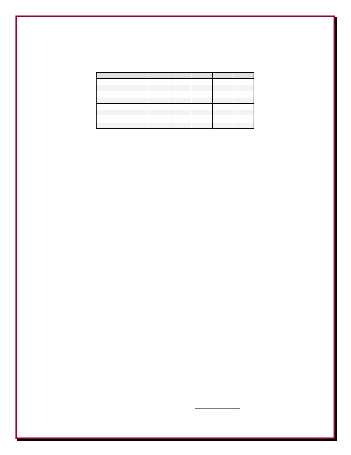
2) When rotating the modified DXE-CC-8A Control Console switch from position 1, 2, 3 and 4, if all
Switch Position
G A B C D
1
GND 0 0
0 1 2
GND 1 0
0 1 3
GND
0 1 0
1
4
GND
1
1 0 1
5
GND 0 0
1
1
6
GND 1 0
1
1
7
GND
0
1 1 1
8
GND
1 1 1
1
LEDs light normally, measure BCD output voltages. Nominally, +12. Connections A, B, C and D,
reference to the ground pin G as shown below. The selected position will supply the BCD logic voltage
as shown in the chart below.
Table 1 - Modified CC-8A Output Truth Table
“1” Equals +12 Vdc (Default)
3) If the voltages are not normal, less than +10 to 18 Vdc, with the control line connected, then disconnect
the control line and retest the modified DXE-CC-8A Control Console. If voltages that were not correct,
are now okay, that indicates a short in the control line or a problem in or beyond the Receive Eight
Circle System relay unit.
4) If the modified DXE-CC-8A has only a couple LEDs lit with the control cable disconnected, then it
may have sustained lightning pulse damage and will need to be repaired or replaced. A new modified
DXE-CC-8A is available from DX Engineering.
Continue troubleshooting the array control with a good modified DXE-CC-8A or by using a 1A fused
power source.
5) Determine if the control line is intact by resistance or voltage testing each conductor for shorts with the
far end of the control cable disconnected from the Receive Eight Circle System unit.
6) With a good modified DXE-CC-8A or other power source connected, measure A, B, C and D control
conductor voltages at the Receive Eight Circle System relay unit with the control cable connected, and
again at the end of the control cable that is disconnected from the Receive Eight Circle System relay
unit. If measured voltages are not between +10 to 18 Vdc on the selected line, a resistive, short or open
circuit problem exists in the control line or in the Receive Eight Circle System relay unit or antenna
feedlines. Normal voltages on the connected control line will cause relays to switch inside the Receive
Eight Circle System unit. If switching voltages are correct, lack of system directivity or gaps in
reception may be due to antenna, feedline or delay line issues.
7) Test the Active Antennas by feeding a voltage on the tested control line A and/or B conductor(s) to
select one direction of Receive Eight Circle System unit operation. Simultaneously feed normal
operating voltage on the tested conductor that powers the Active Verticals for reception. If a low value
fuse blows, then a short circuit may be isolated by disconnecting antennas and reconnecting them one at
a time.
If no fuses have blown and connected voltages stay near the nominal +12 Vdc levels, then:
8) Test for active operating voltage at the end of each antenna feedline. If all are good, proceed. If not,
repair feedlines and/or connectors. If voltage is present on the power line to the Receive Eight Circle
System relay unit, but is not measured at the end of good feedlines, inspect inside Receive Eight Circle
System relay unit to determine if there is an obvious reason that Active Vertical Antenna power is not
making it out the antenna ports. A bad connection outside of the RFS relay unit is usually the problem,
and rarely has a component failure inside the Receive Eight Circle System relay unit been discovered.
Proper Receive Eight Circle System phasing requires that each Active Vertical Antenna, and its
respective equal length feedline, actually provides the same signal level to the Receive Eight Circle
System unit. Use a steady, non-fading ground wave signal from a low or medium power daytime AM
- 27 -

Broadcast station that is over 10 miles away, on a frequency high in the band, or another constant signal
source near 160 or 80 meters, well away from the array, to test that each Active Vertical receives the
same signal level. Do not use sky wave or night signals for these signal level tests.
9) Test reception of each Active Vertical Antenna by connecting each antenna feedline, one at a time, to an
activated port on the Receive Eight Circle System. This assumes that a good port has been identified
and is functioning properly. Normal reception must be confirmed from each antenna. If any antenna is
not providing the proper RF signal level, move the AVA unit to a known good feedline position to rule
out the possibility that a bad feedline is attenuating the RF. If one or more Active Receive Verticals
produce a low or no signal, then the AVA unit at the base of that antenna may not be receiving power.
Retest for DC power at the antenna end of that feedline. If + 10 to 18 Vdc is found, then the Active unit
may need to be serviced or replaced. New DXE-AVA-2 units are available separately by calling DX
Engineering.
10) If all Active Verticals tested provide the same signal level, then change switching voltages to activate
the other ports, one at a time, and test each Receive Eight Circle System unit port, using one of the good
antennas, testing for the same level of reception. If one or more ports is dead or has diminished
reception, there may be a problem in a delay line or in the Receive Eight Circle System unit.
11) Using tested or replaced delay lines and connectors, if one or more ports is dead or has diminished
reception, the Receive Eight Circle System unit may require service or replacement.
At this point, the problem in your system should have been identified. If you need additional assistance from
DX Engineering, feel free to call or write. Detailed discussions of system function, connections, and
troubleshooting is best handled by telephone, Monday through Friday, 8:30 am to 4:30 pm Eastern Time, at
330-572-3200.
Technical Support
If you have questions about this product, or if you experience difficulties during the installation, contact DX
Engineering at (330) 572-3200. You can also e-mail us at: DXEngineering@DXEngineering.com
For best service, please take a few minutes to review this manual before you call.
Warranty
All products manufactured by DX Engineering are warranted to be free from defects in material and workmanship for a period of one (1) year from
date of shipment. DX Engineering’s sole obligation under these warranties shall be to issue credit, repair or replace any item or part thereof which is
proved to be other than as warranted; no allowance shall be made for any labor charges of Buyer for replacement of parts, adjustment or repairs, or
any other work, unless such charges are authorized in advance by DX Engineering. If DX Engineering’s products are claimed to be defective in
material or workmanship, DX Engineering shall, upon prompt notice thereof, issue shipping instructions for return to DX Engineering (transportationcharges prepaid by Buyer). Every such claim for breach of these warranties shall be deemed to be waived by Buyer unless made in writing. The above
warranties shall not extend to any products or parts thereof which have been subjected to any misuse or neglect, damaged by accident, rendered
defective by reason of improper installation, damaged from severe weather including floods, or abnormal environmental conditions such as prolonged
exposure to corrosives or power surges, or by the performance of repairs or alterations outside of our plant, and shall not apply to any goods or parts
thereof furnished by Buyer or acquired from others at Buyer’s specifications. In addition, DX Engineering’s warranties do not extend to other
equipment and parts manufactured by others except to the extent of the original manufacturer’s warranty to DX Engineering. The obligations under
the foregoing warranties are limited to the precise terms thereof. These warranties provide exclusive remedies, expressly in lieu of all other remedies
including claims for special or consequential damages. SELLER NEITHER MAKES NOR ASSUMES ANY OTHER WARRANTY
WHATSOEVER, WHETHER EXPRESS, STATUTORY, OR IMPLIED, INCLUDING WARRANTIES OF MERCHANTABILITY AND
FITNESS, AND NO PERSON IS AUTHORIZED TO ASSUME FOR DX ENGINEERING ANY OBLIGATION OR LIABILITY NOT STRICTLY
IN ACCORDANCE WITH THE FOREGOING.
©DX Engineering 2018
DX Engineering®, DXE®, DX Engineering, Inc.®, Hot Rodz®, Maxi-Core®, DX Engineering THUNDERBOLT®, DX Engineering Yagi Mechanical®,
EZ-BUILD®, TELREX®, Gorilla Grip® Stainless Steel Boom Clamps, Butternut®, SkyHawk™, SkyLark™, SecureMount™, OMNI-TILT™, RFPRO-1B®, AFHD-4® are trademarks of PDS Electronics, Inc. No license to use or reproduce any of these trademarks or other trademarks is given or
implied. All other brands and product names are the trademarks of their respective owners.
Specifications subject to change without notice.
- 28 -
 Loading...