

Page 1

- 1 -
Receive Antenna Phasing
Controller
DXE-NCC-2
U.S. Patent No. 8,175,546
DXE-NCC-2-INS Rev 2
© DX Engineering 2022
1200 Southeast Ave. - Tallmadge, OH 44278 USA
Phone: (800) 777-0703 ∙ Tech Support and International: (330) 572-3200
Fax: (330) 572-3279 ∙ E-mail: DXEngineering@DXEngineering.com
Page 2

- 2 -
Table of Contents
Introduction
3
Features
5
Functions and Technical Description
6
Understanding Noise and Interference
10
Reducing Noise and Interference
10
Selecting Antennas
11
Receive Antennas
11
Antenna Polarization
12
Antenna Feedlines
12
Antenna Sensitivity
12
Antenna Bandwidth
13
Combining Antennas to Improve Signal-to-Noise Ratio
13
Use with a Receive Loop or Other Low Noise Antennas
14
Phased Verticals and Beverage Systems
14
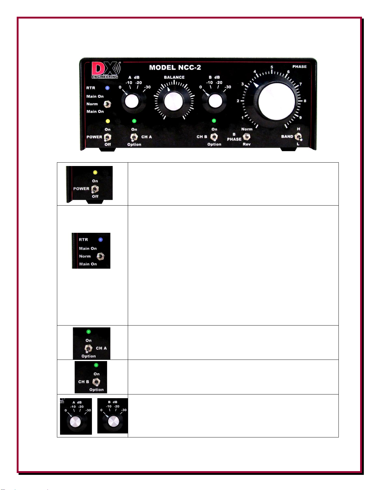
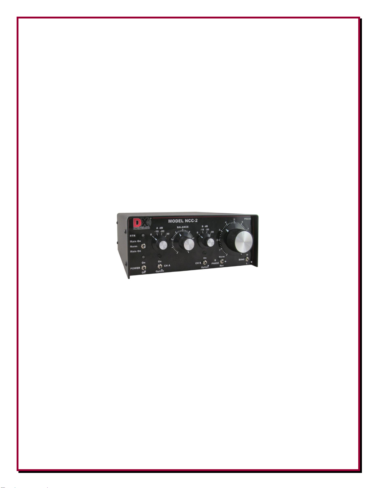
Front Panel Controls and Switches
15
Rear Panel Connections
17
More on RADIO PTT - RX ENABLE Failsafe Feature
18
DXE-KWD-RTR Cable Information
19
Internal Jumpers
20
Bias Tee Enable
21
Force Ground
21
Bias Tee Always On
22
Installation
22
Connections
22
Operation
24
Using the NCC-2
25
Phase Nulling with a Transmit Antenna
26
Interconnection Diagrams
27
Appendix A
33
Internal Optional Modules
33
Removing - Installing Optional Modules or Bypass Plug-In Boards
34
Specifications
35
User Diagram
35
Technical Support
36
Manual Updates
36
Warranty
36
Page 3

- 3 -
Introduction
The DX Engineering NCC-2 Receive Antenna Phasing System Controller is a two-channel receive
signal phasing device with a special relay system that allows the user to combine and independently
adjust the phase and level between two antenna inputs. This essentially creates a fully adjustable
phased array. When combining two stationary antennas, an array pattern is created with signal
peaks and dips, called nulls. Adjusting the phase control has the effect of electronically rotating or
steering that pattern. The operator can steer the null direction to significantly weaken strong
interfering signals or noise, local or distant, and dramatically enhance the reception of weaker
signals from other directions. The NCC-2 is especially useful on low frequencies, where phase
nulling with small receive antennas can provide amazing benefits for almost all types of radio
operating enthusiasts: DXers, casual conversationalists, contesters, AM DXers and Short Wave
Listeners (SWL) throughout HF.
The NCC-2 Controller includes the RTR Receive Transmit Relay, which expands the exciting
benefits of antenna phasing for interference reduction in two ways. First, the NCC-2 can combine
signals from an HF transmit antenna and a separate receive antenna. Almost any Amateur, even
those with space-limitations for separating the receiving and transmitting antennas, can enjoy the
benefits of antenna phasing and noise-nulling to effectively notch-out strong stations or noise.
Second, the user of any standard HF transceiver, that does not have a separate receive antenna input,
can enjoy the enhanced reception of signal and noise nulling. The NCC-2 has rear panel SO-239, F
and BNC connectors, making it extremely versatile and easy to connect to almost any receiver or
HF transceiver as well as transmit and receive antennas.
The NCC-2 features three internal
slots per input channel for optional
Plug-In Modules that can also
improve reception. Receive
Preamplifier Plug-In Modules are
crucial for low-signal conditions.
Receiver Guard Plug-In Modules
offer front-end protection for the
NCC-2 and the receiver. Plus, the
Impedance Transformer Plug-In
Modules match the 75 ohm
receive-antenna feedlines to the 50
ohm internal impedance of the
NCC-2 and the Receive Preamp.
Optimal results with the NCC-2 are achieved with identical vertical receive antennas. The complete
package including the DXE-NCC-2 and DXE-RSEAV-2 is known as the Active Antenna Phasing
System. This receive only combination is shown in Diagram 3 on page 29. Bidirectional receive
performance is from 500 kHz to 15 MHz. The pair of Receive Short Element Active Verticals,
DXE-RSEAV-2, installed with a spacing of one-quarter wavelength on the lowest band, phased
together with the NCC-2, delivers an electronically steerable, optimized unidirectional pattern with
a single null. Operations on higher frequency bands results in a multiple null pattern that is very
useful. The NCC-2 front panel controls provide repeatable directional pattern adjustments. Properly
Page 4

- 4 -
spaced Active Receive Vertical antennas are useable over a wide range of frequencies, offering the
best possible nulling and peaking for enhanced weak signal reception.
The NCC-2 is also fully compatible with the DX Engineering Active Magnetic Loop; model DXE-
RF-PRO-1B, for phasing with a directional low-noise antenna. Although Active Verticals and
Active Magnetic Loops typically deliver the best results, the NCC-2 is ready for experimentation
with other combinations of receiving antennas including Single and Reversible Beverage and
Beverage On the Ground Antennas, Receive Four-Square and Eight Circle Arrays, K9AY Loops,
and more. The NCC-2 is primarily designed for 500 kHz to 15 MHz use, although the useful
operating range extends from below 300 kHz to 30 MHz. Typical applications include:
Combining two similar non-directional antenna elements to create a directional pattern
Combining two similar directional antennas to produce an enhanced pattern
Reducing overload or interference by removing or reducing a strong signal or noise
Reducing interference from distant signals or noise
The NCC-2 has four main advantages over typical directional phased array systems:
The NCC-2 array can be steered “electronically” even though the antennas are
physically stationary
The user can adjust the controls to obtain a null or a peak
The phased response can often be changed from a perfect null to the perfect peak with a
flip of a switch
Front panel adjustments compensate for less-than-ideal installations, making a
directional array possible in most situations
NOTE: A transceiver amplifier keying line must be connected, to activate a very important
feature of the NCC-2. The RTR Receive Transmit Relay has a unique Failsafe System, which
protects the unit and your receive antenna equipment when the NCC-2 is connected to a transceiver
RF output. When the NCC-2 is off, the transceiver RF output (RADIO) is connected by the relay
directly to the transmit antenna (MAIN ANT). This prevents internal RF damage and allows regular
station operations when not using the NCC-2. Conversely, reception of the phased antenna signals
on the RADIO is allowed ONLY when the NCC-2 is on, the RTR Switch is in the NORM position
AND a transceiver amplifier keying line is connected from the dual-purpose dual conductor
RADIO PTT connector, carrying the special RX ENABLE output signal on the keying line shield
to the transceiver chassis and back on the coaxial cable shield. The keying cable is the failsafe
interlock and the “Receive Enabled" condition is confirmed by the RTR LED change to BLUE.
When the transceiver is keyed to transmit, the transceiver amplifier keying line center conductor
carries the typical “Ground on Transmit” to the NCC-2 RADIO PTT input. The RTR LED changes
to RED and the high-speed RTR relay immediately connects the transceiver RF output to the
transmit antenna. Simultaneously, if enabled by internal jumper, DC power is disabled on the
receive feedlines to Active antennas. Toggling your transceiver to listen between phased antenna
receive and the transmit antenna is easy with the RTR Switch MAIN ON momentary and set
positions. Remember, the "no receive" MAIN ANT to RADIO transmit condition exists when the
RADIO PTT – RX ENABLE keying line is NOT connected or if NCC-2 power is turned off. See
more details in the manual sections entitled “See More on Radio PTT – RX Enable Failsafe
Feature” and “NCC-2 Functions and Technical Description.”
Page 5

- 5 -
DX Engineering NCC-2 Features
RTR system supports phasing a transmit antenna with a separate receive antenna
RTR system supports transceivers without a separate receive antenna input
Enhanced Phase control – adjusts through 360 degrees within primary design frequency
range 500 kHz to 15 MHz. Useable freq. range 300 kHz to 30 MHz.
Improved Balance control with easier adjustment for deeper nulls
Exceptional dynamic range – handles strong signals without overload
Low noise floor - operational balance and phasing system optimized for low signals
High Third Order Intercept – approaches, matches or exceeded many radios; +32 dBm
per channel, +38 dBm both inputs combined
Three internal option slots per channel for Plug-In Modules:
Receive Preamplifier (DXE-RPA-2-PM)
Receiver Guard (DXE-RG5000HD-PM)
75 to 50 ohm Impedance Transformer (DXE-IT-PM)
Internal 50 ohm impedance – rear panel SO-239 for RADIO and MAIN ANT
Receive Antenna Input Channels – BNC for 50 ohm and F connector for 75 ohm
feedlines (use 75 to 50 ohm Impedance Transformer Plug-In Modules - DXE-IT-PM)
RTR system automatically switches from phased antenna reception to transmit antenna
(when using a transceiver RF output)
Handles up to 200 watts (CW) of transmitted RF
Radio to amp keying line input RCA female (RADIO PTT) with RX Enable interlock
supports RTR failsafe to prevent RF damage to NCC-2
Accessory keying line output RCA female (ACC PTT) ‘ground on transmit’ Schottky
diode isolated pass-through from RADIO PTT transceiver amp keying for Amplifier or
Accessory
Multi-Color Status Indicating LEDs for Power, RTR Mode and Preamp Power CH A
and CH B
Internal jumper to enable DC injection onto receive feedline for Active Vertical or
Magnetic Loop Antennas
Screw-on version of the DC Power connector is provided to prevent accidental power
cable pull-out (any type 2.1 mm DC Power connector may be used)
Operates on +13.8 Vdc nominal, accepts and operates on any voltage from +13 to +21
Vdc input to power the NCC-2. Input DC line should be fused at 3 amps to protect
circuitry. For Active Verticals that are connected, the voltage may have to be +13.6 Vdc
or higher. Some loops may require +21 Vdc.
Note: Every radio manufacturer’s accessory interconnection scheme is different.
Consult your radio manufacturer’s manual for details and requirements for receive
signal inputs, outputs and switching voltages.
A new keying line cable assembly for most Kenwood transceivers with a 7-pin DIN Remote
connector, is the DXE-KWD-RTR. This custom cable allows proper operation of a Kenwood
transceiver with the NCC-2. See the section ‘More on Radio PTT – RX Enable Fail Safe Feature’.
Page 6

- 6 -
NCC-2 Functions and Technical Description
The DX Engineering NCC-2 is a multi-purpose two-channel phasing controller that features high
signal level handling and very low internal noise. Taking advantage of the time-delay of signal
arrival between two antennas spaced by a significant fraction (1/10) of a wavelength or greater, the
antenna array creates a directional pattern. Successful combinations of antennas and phasing
adjustments create a direction-rotating effect of the resulting array pattern. Changing the phase can
move the sharply reduced signal level of the pattern, known as the null, over the direction of an
interfering noise or signal. The result is the ability to hear signals from other directions that may not
have been heard otherwise.
Note: Effective and proper operation occurs when the same noise (for noise nulling) or the same
signal (for signal nulling or peaking) is present on both CH A and CH B receive antenna inputs.
Directly connected to the CH A and CH B Inputs are the NCC-2 Option Slots. Bypass Plug-In
boards are in place to carry input RF directly to the Channel A and Channel B phasing and
combiner systems. The DX Engineering Plug-In Modules function exclusively for the NCC-2
operational protection and enhancements. There are three option slots for each input channel. The
typical order of option installation is:
Option 1 - top slots are intended for 75 to 50 ohm Impedance Transformers (DXE-IT-PM)
when 75 ohm receive antenna feedlines are connected to either the F connectors or the BNC
connectors on the CH A RX ANT INPUT or the CH B RX ANT INPUT. Without these
transformers, both inputs are 50 ohms, the internal impedance of the NCC-2. Impedance
mismatch losses are acceptable if they are not installed; operations will not be adversely
impacted.
Option 2 – middle slots may be used for the Receiver Guard Plug-In Modules (DXE-
RG5000HD-PM) when high signal levels are anticipated to occur on an input.
Option 3 – bottom slots, switched and powered are reserved for Receive Preamplifier Plug-
In Modules (DXE-RPA-2-PM) as controlled by CH A Option and CH B Option switches.
When the NCC-2 is used with passive receive antennas the installation of the RPA-2 plug-in
modules is highly recommended to enhance low signal levels due to propagation. Optional
Preamplifier Plug-In Modules may not be needed when using or with Active Receive
Verticals (DXE-RSEAV-1 or -2).
See Appendix A for special information on removal of Bypass Plug-In boards and installation of
Plug-In Modules.
Page 7

- 7 -
NCC-2 Functions and Technical Description (continued)
Following the input modules slots, the NCC-2 maintains complete RF isolation between the two
channels, beginning with dual, voltage controlled attenuators. They maintain high-stability phasing
with low noise receive antennas, as the voltage controlled step attenuators and cross-channel
Balance control offers consistent operation for repeatable settings. High dynamic range operational
amplifiers buffer the input to the phasing system.
Voltages for phase adjustment are linearized through an active feedback system. Phase adjustment
is spread over a wide linear control range. This gives the phase control a smooth feel and improves
the ability to manually reset it.
The NCC-2 uses two exceptionally flat-response phasing bridge systems and a unique system of
mirrored bridges in each channel. When phase delay is increased in one channel, phase delay is
simultaneously decreased in the other channel. Any level changes while adjusting phase are
automatically compensated in the other channel. There is virtually no channel balance error over the
entire range of the phase control.
The NCC-2 has a dynamic range up to 30 dB (1000 times) better than other popular noise canceling
systems. It also has provisions for further improvements in exceptionally strong signal
environments.
The Channel B phase, normally at 180 degrees, can be inverted to 0 degrees with the B PHASE
Switch, to cover all phasing possibilities. This switch typically inverts a perfect null to a perfect
peak in signal response.
The phased signals from Channel A and Channel B are mixed in the final Signal Combiner. This
phased receive output is delivered only via the RADIO connector, as protected by the RTR Receive Transmit Relay.
The NCC-2 MAIN ANT IN and RADIO connectors that handle transmit RF, and the Phase
Combiner Output, are managed by the high-speed RTR relay. This is a reverse-logic relay which
prevents reception of the phase receive signals unless certain connections are met, thereby
preventing the transmitted signal from reaching the Phase Combiner.
Page 8

- 8 -
In Figure A, the NCC-2 is in MAIN ANT mode or transmit mode, the MAIN ANT IN is internally
connected to the RADIO when the power is turned Off.
The unit stays in the MAIN ANT mode and the RTR LED goes to Red when:
An antenna is connected to MAIN ANT IN
A coaxial cable is connected from the transceiver RF output to RADIO
The Power switch is set to On
The RTR mode switch is in Main On momentary or On position (not center position)
There is a keying line cable from the transceiver to the RADIO PTT – RX ENABLE
connector. Even when the NCC-2 is turned On the Red LED will be dark when no keying
cable is connected. This is a reminder to install the keying cable.
Figure A
NOTE: No reception of the Phase Combiner output is possible when the keying line is not
connected. Exception* - See page 9
When the NCC-2 is in the MAIN ANT mode, and even when independently jumper enabled, NCC2 input DC voltage (+13.6 to +21 Vdc) is interrupted and NOT fed onto either the CH A RX ANT
IN and/or CH B RX ANT IN to operate Active antenna(s) – See section on Internal Jumpers.
----------
In Figure B, the NCC-2 is in RX Enabled Mode and the RTR LED turns to BLUE, allowing the
RADIO to be connected to the CH A and CH B Phase Combiner output. This mode, the receiveenabled condition depends upon all of these items:
A coaxial cable is connected from the transceiver RF output to RADIO (or from
transceiver RX ANT IN)
The Power switch is set to On
The RTR mode switch is set to the Norm position
The transceiver amp keying line is connected to RADIO PTT/RX ENABLE, shield to
transceiver chassis, center NOT grounded
The properly connected transceiver is NOT in the transmit mode
When the NCC-2 is RX Enabled Mode, the Phase Combiner signals are sent to the transceiver
connected to RADIO. Also in RX Enabled Mode, these conditions are enabled, as shown in Fig B.
The MAIN ANT IN signal is connected to the MAIN ANT OUT.
When independently jumper enabled, NCC-2 input DC voltage (+13.6 to +21 Vdc) is fed
onto the CH A RX ANT IN and/or CH B RX ANT IN to operate Active antenna(s)
Figure B
Page 9

- 9 -
IMPORTANT NOTE:
There are three crucial uses of the NCC-2 MAIN ANT OUT:
1. When using the NCC-2 to phase the transmit antenna with a receive antenna, the included
BNC patch cable MUST be installed to connect the MAIN ANT OUT into the CH A RX
ANT IN. This is required to feed the transmit antenna’s received signal back in, to
accomplish phasing of that signal with the receive antenna signal that is connected to CH
B RX ANT IN.
See the warning below.
2. When using the NCC-2 MAIN ANT OUT to send the transmit antenna received signal to a
second receiver only, when phasing two receive antennas.
3. When using the NCC-2 MAIN ANT OUT to send the transmit antenna received signal to
an external splitter to share it between a second receiver and CH A RX ANT IN, when
phasing MAIN ANT with one receive antenna.
See the section System Connection Diagrams for details
Warning: DO NOT set “BIAS TEE ENABLE” jumper on RTR-2 PCB right board when the
MAIN ANT OUT is connected to CH A RX ANT IN as described above. See section entitled
Internal Jumpers.
The NCC-2 will immediately revert to MAIN ANT mode, Figure A, RADIO to MAIN ANT IN
as soon as:
The transceiver is keyed to transmit, with a ground on transmit on the keying line center
conductor
The keying line is removed
The POWER is turned Off
The MAIN ANT transmit mode cannot occur when the Exception* condition exists.
*Exception: A keyed condition can be set internally, if the NCC-2 is NEVER going to
be connected to a Transceiver RF OUTPUT, but ONLY to a dedicated
Receiver. For NCC-2 applications where ONLY receive antennas are used,
or for AM DX and SWL operations, the “Force Ground” internal jumper
can “semi-permanently” disable the MAIN ANT transmit and enable
NORM.
See the Internal Jumpers section.
Page 10

- 10 -
Understanding Noise and Interference
Before we can use the NCC-2, we need to understand the challenges for operations on HF. Noise
limits our ability to hear a weak signal on the lower bands. Noise is often an accumulation of many
unwanted signals. Noise from antennas is generally a mixture of local ground wave and ionosphere
propagated noise sources, although many locations suffer with dominant local noise sources.
Noise is generated by randomly polarized sources. Noise polarization is filtered depending on the
method of propagation:
Noise arriving via the ionosphere is randomly polarized. Noise arrives with whatever
polarization the ionosphere favors at the moment. Noise from a distant source has the same
characteristics as a "good" signal.
Sources within a few wavelengths of the antenna arrive randomly polarized. The noise does
not have a dominant polarization and it can either be electric or magnetic field dominant.
Local noise can also be random or directional in nature. Every effort must be made to locate
sources of noise that could be eliminated at the source. Dimmer switches, electric timers,
security lights, and many other items can be sources of unwanted noise. Plasma televisions
are becoming more popular and are a known generator of unwanted noise interference.
Ground wave noises arriving from a significant distance are vertically polarized. The path
along the earth "filters out" and removes any horizontally polarized signals. Horizontal
electric field components are "short circuited" by the conductive earth as they propagate and
are eliminated.
With the exception of ground wave-propagated noise, receiving antenna polarization effects are not
predictable. It is possible vertically polarized antennas may be quieter than horizontally polarized
antennas. Either may be true at different times.
It may be difficult to remove noise with any device when:
Noise and desired signals come from the same direction and elevation angle
Both antennas don’t hear the same noise
The noise source is moving around, or noise sources are coming from several directions at
the same time.
Reducing Noise and Interference
Unlike a conventional noise blanker, the NCC-2 is designed to reduce noise or interference before it
gets to the receiver. The NCC-2 can be effective on all types of noise, including interference
(QRM) from unwanted signals. The NCC-2 allows the user to continuously adjust both phase and
amplitude when combining two antenna inputs. The signal output to the receiver is the addition or
subtraction of signals from two separate antennas. Unwanted directional noise can be removed or
unwanted signals can be cancelled. Desired signals can be peaked or enhanced.
Page 11

- 11 -
The phasing method of signal enhancement or rejection has several advantages.
Interference much stronger than a desired signal can be completely removed without affecting
the signal.
The NCC-2 can be effective with all types of interference and all modes.
Signals can be peaked instead of nulled.
The number of cases where phase nulling can reduce or eliminate interfering signals cannot be overemphasized. The null can be steered to knock out overloading signals, stations with key-clicks,
splatter and intentional jamming noises. There will also be a time when the interfering pile-up can
be nulled to reveal the desired DX station signal coming from another direction.
Selecting Antennas
The NCC-2 generally works best when both antennas have similar patterns, polarization, and
Signal-to-Noise ratios. For the most effective nulling of noise, the antennas on both the A and B
inputs must hear the same unwanted noise and should have similar polarization. You may have to
experiment to find the best antenna, but successful operation more commonly occurs with similar
antennas.
Reducing of distant interference: Close element spacing is more desirable. Close spacing
produces a single null that is wider and more stable. Spacing of 1/4-wavelength or less is most
desirable when nulling distant interference or peaking distant signals. Spacing larger than 1/4wavelength can, at your operating frequency, causes multiple nulls in the patterns.
Reducing of a local noise source: Best performance occurs when the noise antenna "hears" the
noise much louder than it hears desired signals. The noise antenna needs to pick up the largest
amount of noise possible, so it should be located as close to the noise source as possible. In this
case the polarization is unimportant; whatever polarization hears the noise best. The spacing
between antennas, that are being phased together, can be any convenient distance within one
wavelength.
Receiving Antennas
The performance of the NCC-2 is largely dependent on the receiving antennas and their installation.
Please carefully read this section and make adjustments or changes to your antennas before using
the NCC-2.
The NCC-2 will function with almost any combination of antennas but it works best when antennas
have reasonably similar directional patterns. Optimum antenna spacing will vary with the
frequency band and what you are trying to accomplish. There are two general rules for antenna
spacing:
If antennas are too close together (less than 1/10-wavelength), a very stable deep null can be
produced but the system will lose gain or sensitivity.
If the antennas are too far apart (generally more than 1-wavelength) the nulls and peaks in the
pattern will become so sharp it might become impossible to maintain nulls or peaks on sky
Page 12

- 12 -
wave signals. With very wide spacing, signals will fade in and out more rapidly with
ionospheric changes.
A deep stable null should be found in one of the B PHASE switch positions (Norm or Rev).
Multiple nulls may be found in both positions depending upon antenna combinations, their
spacing and the frequency.
Antenna Polarization
It is generally not a good idea to mix polarization of antennas. Although this scheme can work
when nulling a ground wave signal or noise, mixing polarizations generally makes nulls or peaks
more difficult to find and maintain. When receiving skywave propagated signals, mixing a
horizontal antenna with a vertical antenna almost always increases fading. Expect unpredictable
results when combining transmit antennas with receive antennas.
Antenna Feedlines
It is not necessary to use any special length of feedline with antennas used in this system or for
antennas to be "resonant" or physically large. The front panel controls will compensate for feedline
lengths. You should still use a good feedline and make good connections.
The receive antenna inputs (CH A RX ANT IN and CH B RX ANT IN) are 50 ohm using either
BNC or F Connectors.
The MAIN ANT IN and the RADIO connectors are 50 ohm SO-239 connectors.
DX Engineering carries RG6U 75 ohm coaxial cable and weather-tight connectors as well as 50
ohm BNC to BNC cable assemblies. 75 ohm antenna systems and feedlines are supported with the
optional Internal 50 ohm to 75 ohm Transformer (DXE-IT-PM) module.
Antenna Sensitivity
Receiving antennas should not have excessive signal level or gain. They only need enough gain or
signal level to have very weak signals limited by external noise. Too much signal level from
antennas is actually not good. Normally we should just hear a slight increase in noise (or weak
signal) from no antenna connected to having one connected. We would then clearly hear a noise
floor increase. For best weak signal reception, background noise of antennas would ideally be
around 5 dB, or about 1 S-Unit, above the NCC-2 noise floor.
The NCC-2 is a very good match for DX Engineering Receive Short Element Active Vertical
Antennas (RSEAV), closely matching their dynamic range. Higher noise floor antennas can be also
be successfully used due to the built-in front panel adjustable attenuators. Phasing a transmit
antenna and a receive antenna is often more difficult, but can be very productive for noise and
signal nulling.
Page 13

- 13 -
Antenna Bandwidth
Wider bandwidth antennas produce the most stable and reliable performance. Very narrow
bandwidth antennas do not work as well. A small resonant loop will be very narrow in response and
will shift phase rapidly with frequency changes. This means temperature changes and frequency
changes will both require more frequent readjustment of the NCC-2 controls. (Exceptionally wide
spaced antennas also produce a similar effect, as will mixing of antenna polarizations in one
system.)
Combining Antennas to Improve Signal-to-Noise Ratio
If your location is limited by interference coming from many directions, you can use the NCC-2 to
enhance signals. It functions as an electronically rotatable directional receive antenna. The
following guidelines apply when enhancing signals:
The most reliable and consistent phasing
performance occurs with receive antenna
spacing less than 1/4-wavelength when receive
antennas are in line with the desired direction,
and less than 1/2 to 1-wavelength apart when
receive antennas are spaced at right angles to
desired directions.
Best sensitivity occurs when receive antennas
are more than 1/10-wavelength apart when the
receive antennas are in line with the desired
direction, and more than 1/2-wave apart when
broadside to the desired direction.
When enhancing desired signals, it is preferable to locate both A and B INPUT receive
antennas as far from local noise sources as possible.
A DXE-RSEAV-2 pair of Receive Short Element Active Vertical Antennas are the perfect match
for the NCC-2. All three create an Active Phasing System. See Diagram 3 on page 29.
The NCC-2 generally works best when both antennas have similar patterns, polarization, and S/N
ratios. You may have to experiment to find the best antenna, but successful operation occurs more
often with similar antennas.
The best system is often found by planning, although it is often worth experimenting.
When using any of these directional phased antenna arrays you may record phase settings to null
stations from known directions. It is then possible to make a direction chart. With optimal antenna
spacing it is possible to tell direction within several degrees.
Page 14

- 14 -
Use with a Receive Loop or Other Low Noise Antennas
The NCC-2 is probably most useful when used to enhance reception on lower frequencies. The
NCC-2 is often useful even if the station already employs low noise directional receiving arrays.
A suggested method follows:
Connect one DXE-RF-PRO-1B Magnetic Loop or other similar low noise receiving antenna
to CH A
Connect another DXE-RF-PRO-1B Magnetic Loop or another low noise receiving array to
CH B
Connect the NCC-2 RADIO connector to the receiver's antenna input line or transceiver RX
ANT INPUT
It is possible to combine almost any receiving antennas.
For example:
Two verticals can be combined to produce a steerable array capable of peaking or nulling
signals.
Two parallel Beverage antennas spaced an eighth to quarter wave apart with an eighth to
quarter wave stagger in the desired direction can be combined to improve front-to-back ratio
or steer nulls to the direction of unwanted signals or noise.
Page 15
- 15 -
Front Panel Controls and Switches
POWER: Turns power ON and OFF.
LED is Yellow when the POWER switch is Off but the NCC-2 is
connected to an active power supply
LED is Green when POWER switch is turned On
RTR Switch: When the RTR functionality is used and POWER is
On:
LED is Blue with the RADIO PTT line is properly connected to the
radio for RX Enable and switch in Norm position
LED is RED when radio is in transmit mode and when switched to
Main On to listen to MAIN ANT
Three switch positions:
Main On Up: Switches the RADIO to listen to the MAIN ANT
input
NORM: Center position on switch - connects RADIO to phased
antennas (RX Enable)
Main On Down: Momentarily switches RADIO to listen to MAIN
ANT input
On/Off Power Switch for Channel A - Option 3 (bottom) Slot
(When the DXE-RPA2-PM is used, it must be in Option 3 slot)
On/Off Power Switch for Channel B - Option 3 Slot
(When the DXE-RPA2-PM is used, it must be in Option 3, the
bottom slot). See Appendix A
Two rotary Attenuator switches reduce gain in ten dB steps. The
steps are 0, -10, -20, and –30 dB. The left switch sets CH A RX
ANT IN attenuation (primary antenna), the right switch sets CH B
RX ANT IN (secondary antenna) attenuation.
Page 16
- 16 -
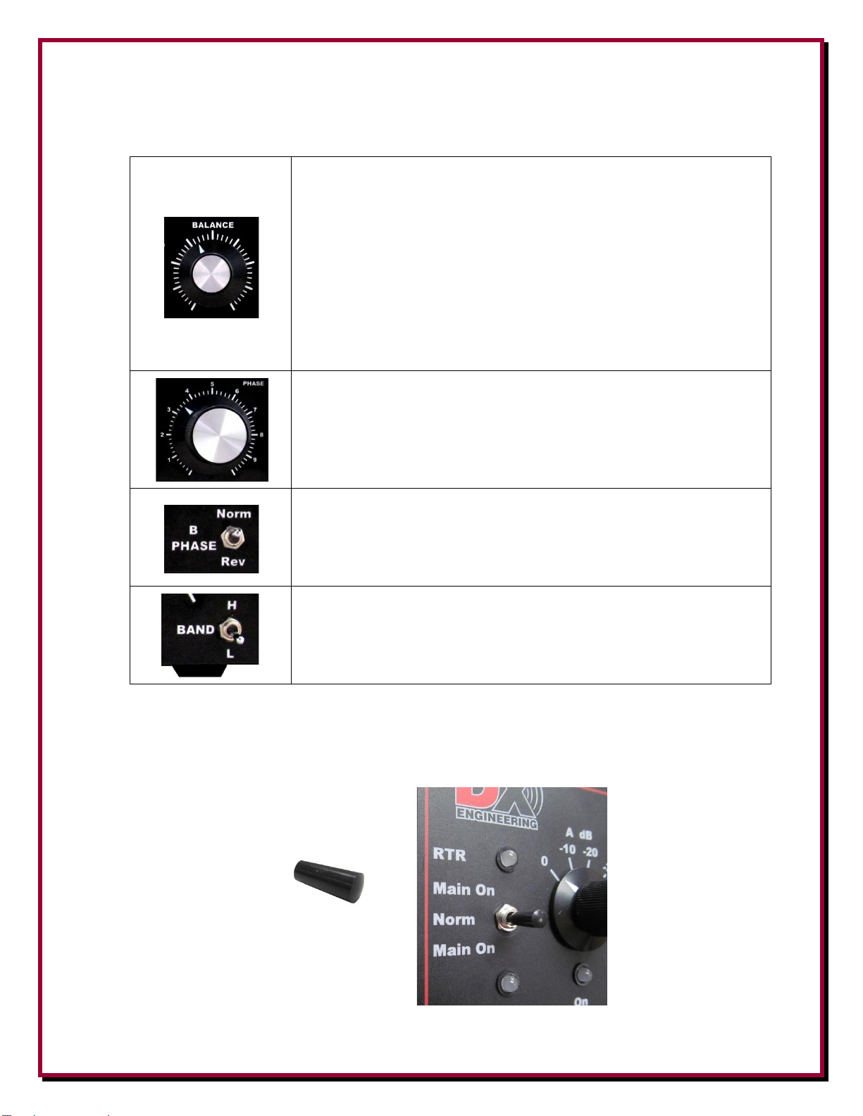
Front Panel Controls and Switches (continued)
BALANCE: Provides fine adjustment of opposite channel
attenuation. It is used to balance or equalize signal levels from CH
A and CH B. The BALANCE control provides anywhere from zero
to 8 dB attenuation on either A or B. This control has the similar
“feel” and operation as the balance controls on conventional stereo
systems. Maximum gain on both channels occurs when the
BALANCE control is positioned in the center of the range, and gain
is reduced as the knob is rotated away from a particular channel. If
you rotate the BALANCE control clockwise, the gain of INPUT A
is reduced. Precise signal or noise level balancing between INPUTS
A and B is required for optimal noise or signal canceling.
PHASE: Changes the phase delay relationship between CH A and
B. The resulting phase shift will change the directional position of
antenna pattern null or peak signal response.
Note: Progressive adjustments of PHASE and BALANCE produce
the best null
B PHASE: Moves B INPUT phase by exactly 180 degrees.
NORM is 180 Degrees or no phase reverse, REV is 0 Degrees.
BAND: Optimizes phase range. "L" selects the low. "H" selects the
high. Use L when operating below 7 MHz. Use H when operating
above 7 MHz.
For those that want a slightly larger switch handle on the RTR switch, a black switch cap has been
included with the NCC-2. Push this cap fully in place as shown below.
Page 17
- 17 -
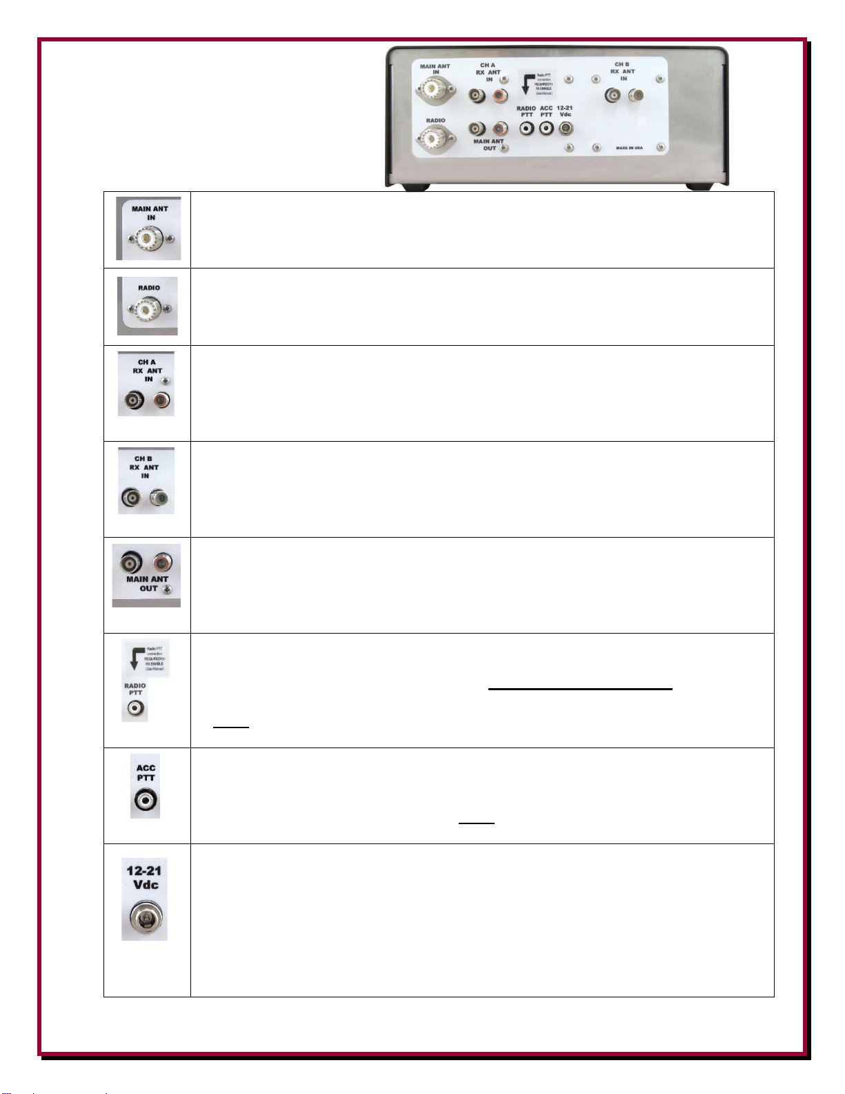
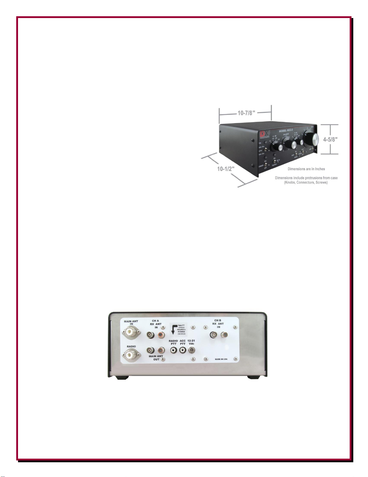
Rear Panel Connections
MAIN ANT IN: SO-239 connector.
Connects to primary transmit antenna. 50 ohm impedance, nominal. This connector
goes to a linear amplifier RF Input, if one is used.
RADIO: SO-239 connector. Connects NCC-2 to Transceiver. 50 ohm impedance,
nominal. Is used for connection to RX ANT INPUT when NCC-2 is not used for
transmit antenna phasing.
CH A RX ANT IN: Primary Receive Antenna – 50 ohm BNC and F style connectors
in parallel. BNC and F style connectors are used to prevent accidental connections to
transmitting equipment. When connecting to a 75 ohm systems, ideally the use of the
optional 50 ohm to 75 ohm transformer plug-in option (DXE-IT-PM) is suggested
for the Channel A Option 1 (top) slot. See appendix A
CH B RX ANT IN: Secondary Receive Antenna – 50 ohm BNC and F style
connectors in parallel. BNC and F style connectors are used to prevent accidental
connections to transmitting equipment. When connecting to a 75 ohm systems,
ideally the use of the optional 50 ohm to 75 ohm transformer plug-in option (DXE-
IT-PM) is suggested for the Channel B Option 1 (top) slot. See appendix A
MAIN ANT OUT: Receive Signal output to second receiver or to CH A RX ANT
IN for RTR phasing of the MAIN ANT. BNC and Type F connector. These types of
connections work well with most transceiver and receiver RX ANT Inputs.
Impedances are not critical. Do not use both connectors at the same time; use a
splitter to share signals - see Diagram 4
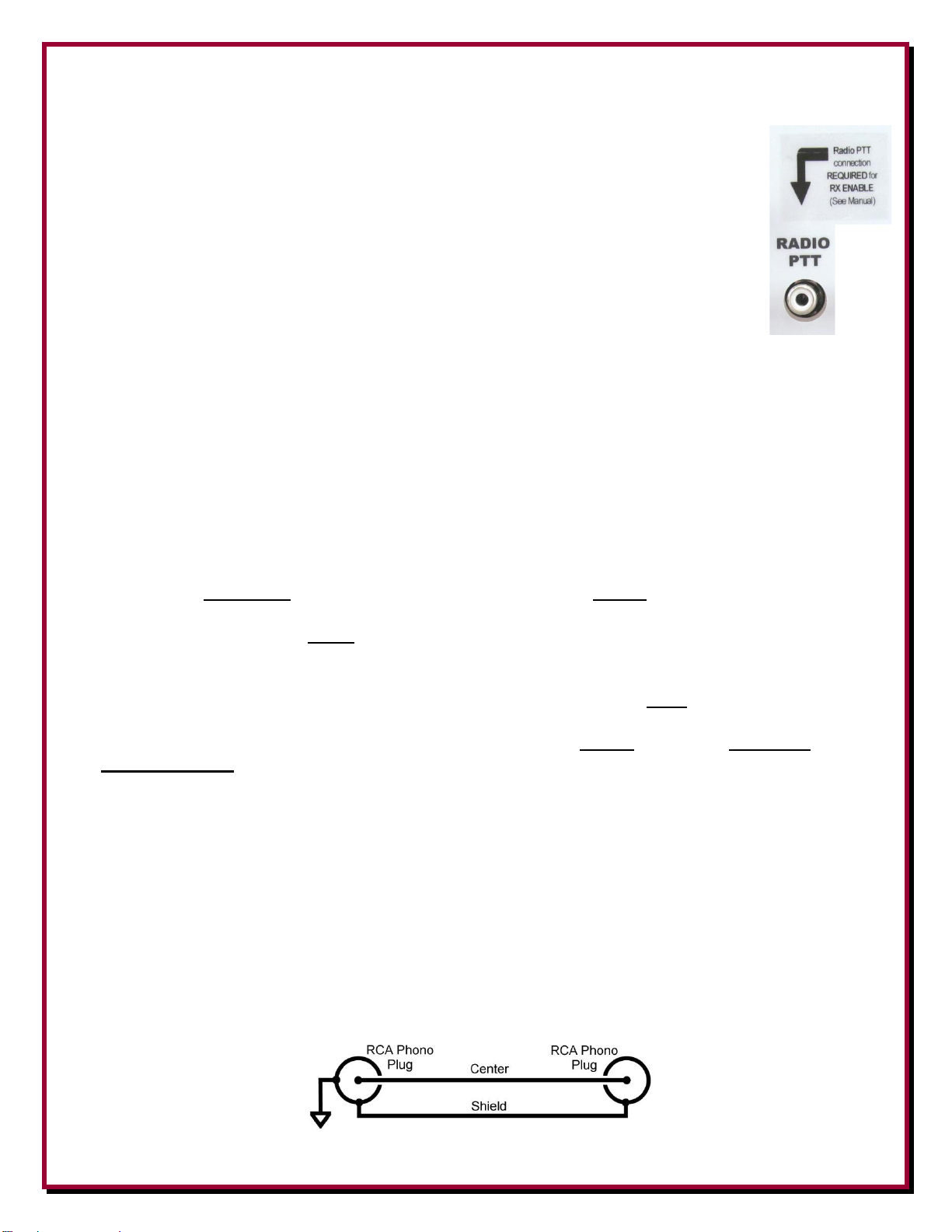
RADIO PTT RX ENABLE: RCA connector - The transmitter amplifier keying line
connection from transceiver or sequencer (ground on transmit). This two-conductor
connection to the transceiver keying output MUST BE CONNECTED to enable
radio reception of phased antennas. This connection is master to the ACC PTT and
is NOT INTERCHANGEABLE with ACC PTT. See section More on Radio PTT-
RX ENABLE
ACC PTT: RCA shielded connector - Keying line pass-through connection for
amplifier or sequencer (grounding keying line only) for automatic relay switching of
an accessory. This connection is a diode protected pass through of the ground on
transmit from the RADIO PTT and is NOT INTERCHANGEABLE with RADIO
PTT. There is no delay in this signal. See section More on Radio PTT-RX ENABLE
12-21 Vdc: The NCC-2 operates on +13.8 Vdc 2A and accepts well-filtered, +13.8
to +21 Vdc for normal NCC-2 operation. Input DC line should be fused at 3 amps to
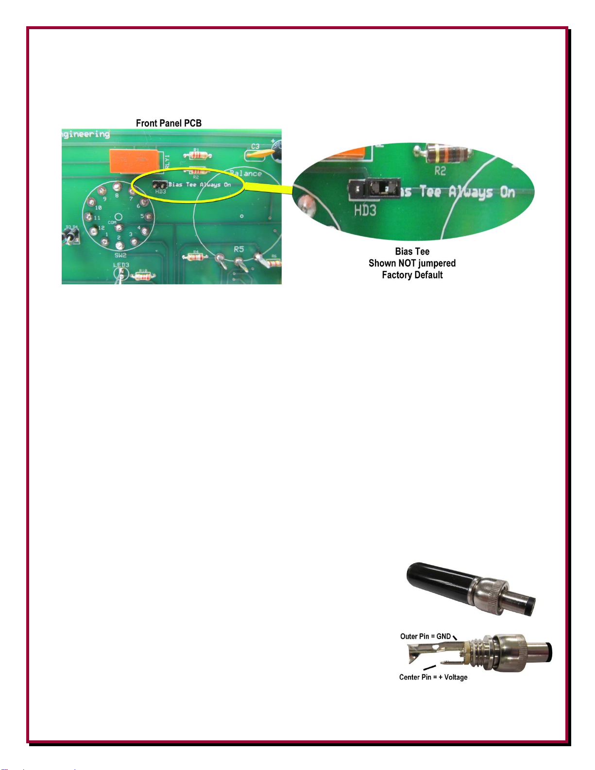
protect circuitry. A 2.1 mm screw on plug, center positive power plug is included
with the NCC-2 which is intended to prevent accidental disconnection (a standard
2.1 mm plug will also work). Most external active antennas are supported with +13.6
Vdc or higher input voltages from the NCC-2 as required. The NCC-2 will accept up
to +21 Vdc input. The use of most switching power supplies is discouraged due to the
presence of noise in their output.
Page 18
- 18 -
More On RADIO PTT – RX ENABLE Failsafe Feature
The proven design of the RADIO PTT-RX ENABLE failsafe feature used in the
RTR-1 is improved for the NCC-2 and the RTR-2.
In the NCC-2, the purpose of the RTR failsafe circuit is to allow phasing of a transmit
antenna and a receive antenna while reducing, to nearly zero, the chances of
accidentally transmitting into the phase combiner (the receive side of the NCC-2).
Therefore, the RTR relay is wired so that when the NCC-2 is turned off, the transceiver
(RADIO) is only connected to the transmit antenna or amplifier (MAIN ANT IN) and
the receive mode is disabled. When the unit is off, you can use your station normally.
See Figure A on page 8.
When the NCC-2 is turned on, RADIO to MAIN ANT IN is the same connection we want when
the transceiver is keyed to transmit, or when we want to listen only to the transmit antenna (MAIN
ON). Okay, let’s tell the NCC-2 when it is safe to switch to receive mode. Well, unfortunately, we
can’t because transceivers don’t put out an “Okay to Receive” signal, they only send out a “Hey,
I’m transmitting signal” on the amplifier keying line (RADIO PTT).
So when we want to switch the NCC-2 to the receive mode (NORM), and RADIO is connected to
the Phase Combiner (Figure B on page 8), we have to be absolutely certain that the transceiver
amplifier keying signal, which automatically switches the RADIO back to the MAIN ANT, is
always there, OR ELSE! That transceiver amplifier keying cable MUST be installed. But, how can
the NCC-2 know that it is safe to go to the receive NORM mode? It does it with the RX ENABLE
signal, which is sent on the shield of the RADIO PTT keying cable to the chassis of the
transceiver, and back on the RF coaxial cable shield. No keying cable? No receive! Only transmit.
How can that work? Simple; the shield of the RADIO PTT connector is NOT at NCC-2 chassis
ground. It carries the RX ENABLE voltage that is looking for the NCC-2 chassis ground. The
keying cable and a coaxial cable from the transceiver to NCC-2 MUST be in place. This is the
failsafe interlock.
Let us say it another way: The RX ENABLE signal travels from the RADIO PTT on the shield of
the keying cable to the transceiver chassis ground. The transceiver amplifier keying signal on the
center conductor takes the NCC-2 out of the receive mode, sending the RADIO back to the MAIN
ANT IN. Of course, the amplifier keying signal is sent on to your amplifier without delay, through
a Schottky-diode for isolation, via the ACC PTT connector. (See the caution on the next page).
The RADIO PTT – RX ENABLE keying cable can be as simple as a common RCA audio patch
cable connection from certain transceivers that have an RCA keying connector that has its shell at
chassis ground. On other transceivers with special connectors it may not be quite so simple, but
normally the amp keying line shield is chassis ground, as shown here.
Transceiver Amplifier NCC-2
Keying Connector Radio PTT
Page 19
- 19 -
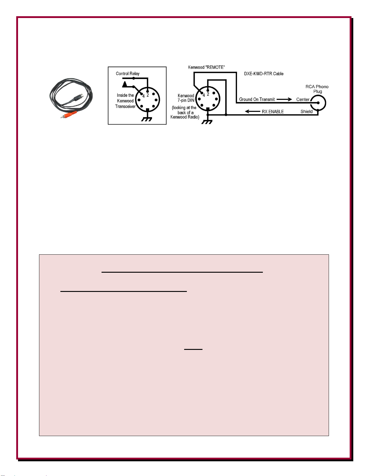
However, on many Kenwood transceivers, the amp keying relay common is not chassis ground. So
you need a special cable that takes the shield to chassis ground. The DXE-KWD-RTR is available
from DX Engineering.
The DX Engineering special RTR to Kenwood cable assembly for Kenwood transceivers adds the
shield to the chassis ground connection on the 7-pin DIN shell. Ground On Transmit and RX
ENABLE are thereby both functional for the NCC-2, RTR-2 and RTR-1 units with the DXE-
KWD-RTR cable. Note: The DXE-KWD-RTR cable does not provide ALC line due to its lack of
need or use.
The following Kenwood radios are known to have the 7-pin DIN REMOTE connector for amplifier
keying line connection and can use the DXE-KWD-RTR cable:
TS-120, TS-130, TS-140S,TS-2000, TS-2000X, TS-B2000,TS-430S, TS-440S, TS-450S,
TS-50S, TS-530S, TS-570D, TS-570DG,TS-570S, TS-570SG, TS-590S, TS-590SG, TS680S, TS-690, TS-690S,TS-850S, TS-870S, TS-930S (Some early unmodified TS-930
models are not supported), TS-950S, TS-950SDX, TS-990S
KEYING LINE CONNECTION WARNING:
MAKE ABSOLUTELY CERTAIN that the KEYING LINE from the
TRANSCEIVER is connected ONLY to the NCC-2 RADIO PTT
connector. The keying line to the amplifier must be connected ONLY
to ACC PTT “pass through”.
Do Not reverse the RADIO PTT and ACC PTT keying line connectors.
These connections are NOT interchangeable.
When the NCC-2 RADIO connector is used to carry transmitted RF, if
these keying connectors are accidently reversed, PERMANENT
INTERNAL DAMAGE will occur to the NCC-2 and potentially to
other receive antenna devices.
INTERNAL DAMAGE TO THE NCC-2 DUE TO REVERSAL OF
KEYING LINES IS NOT COVERED UNDER WARRANTY.
Page 20
- 20 -
Internal Jumpers
The NCC-2 has internal jumpers that configure the placement of DC power onto CH A RX ANT
IN and CH B RX ANT IN independently. As delivered from DX Engineering, the NCC-2 internal
jumpers are positioned for normal operation with no DC power on the antenna input connectors.
With the unit unplugged and no power connected, remove the four screws on each side of the cover
and lift the cover off.
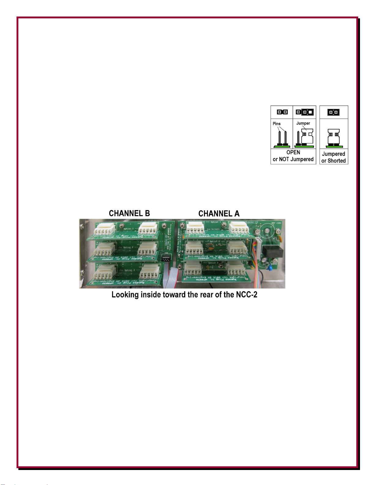
The jumpers are small plugs that fit over and connect two of the pins on the
associated header. The jumper is removed by pulling straight out and
installed by aligning with two pins and pushing straight in to fully seat the
jumper. When a jumper is not used and to avoid losing it, push the jumper
onto one pin on the header.
Looking inside the NCC-2 toward the rear of the unit are two printed circuit boards. The PCB on
the left is sometimes called the RTS Board or Channel B Board. The board on the right is
sometimes called the RTR Board or Channel A Board.
It may be easier to remove the Option 1 and Option 2 By-Pass Plug In boards to have a clear view
and easily check/change the jumpers. Refer to “Appendix A” for removal or installation of these
boards.
Page 21
- 21 -
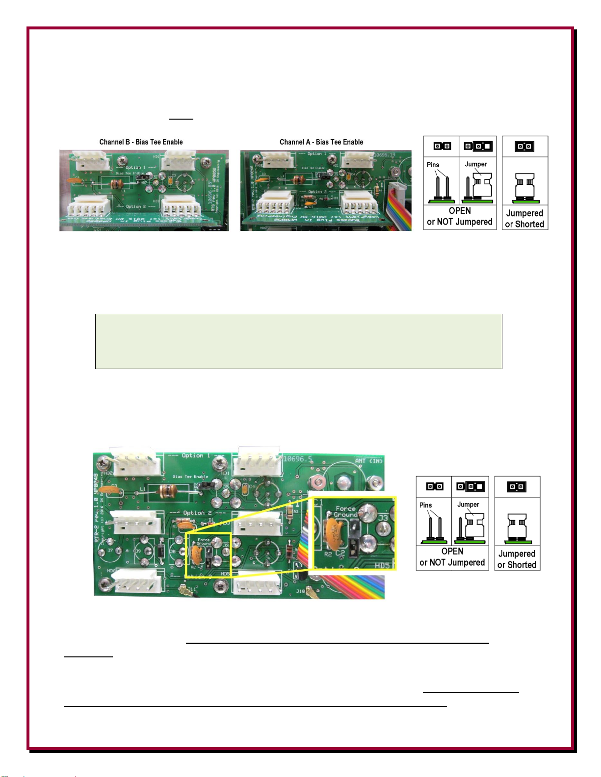
Bias Tee Enable
In between the Option 1 and Option 2 areas of both boards there are headers with jumpers labeled
“Bias Tee Enable” (one on both the Channel B and Channel A boards. The factory default for
these two jumpers is open (NOT jumpered together).
For passive receive antennas both of the “Bias Tee Enable” jumpers are open (factory default).
When both “Bias Tee Enable” jumpers are in place (both pins of the header are connected together
with the jumper), the Bias Tee voltage is connected to the CH A RX ANT IN and CH B RX ANT
IN receiver antenna input connectors (BNC and F).
CAUTION: DO NOT JUMPER the Bias Tee Enable headers on the RTR-2
(Channel A Board) when CH A RX ANT IN is connected to MAIN ANT OUT
for transmit antenna phasing.
If this jumper is connected in error, internal damage will result.
Force Ground
On the Channel A or RTR Board between the Option 2 and Option 3 By-Pass Plug In boards there
is one header with a jumper called “Force Ground”. This jumper is normally left open (factory
default).
NOTE: If this jumper is installed (header pins are connected to each other with a jumper) the
internal safety mechanism is defeated. This safety mechanism is intended to protect the NCC2 from transmit energy. DO NOT use this jumper for typical amateur radio transmit
functions.
This jumper is only used for applications where the NCC-2 is going to be used only with receive
antennas and any transceiver RF output will never connected to the NCC-2. Never use with any
type of TRANSMIT antennas when the “Force Ground” jumper is installed.
Page 22
- 22 -
Bias Tee Always On
The front panel on the NCC-2 has one header with a jumper labeled “Bias Tee Always On” as
shown below. The factory default for this jumper is open - the header pins are NOT connected
together).
When this jumper is connected (both pins on the header are shorted together with the jumper), Bias
Tee voltage is present regardless of transmit and receive keying. This jumper should only be
installed for non-RTR, receive only use of the NCC-2. Conversely, Keyed Bias Tee voltage on the
receive feedlines is normally desired when using any transmitter, unless receive antennas are
located over one wavelength away from transmit antennas.
Installation
Please read the following section carefully.
The best location for this unit is at the operating position with easy access to the controls since you
will be using the S-Meter and listening to your receiver while adjusting the NCC-2.
Connections
Make connections to the NCC-2 as follows:
Connect a fused power source of +13.8 to +21 Vdc 2A
minimum, well filtered and fused to the 2.1 mm center is
positive MAIN PWR jack using the included 2.1 mm
screw-in plug. Well filtered and fused station power is
recommended. For most operations (no loops or special
receive antennas) using your shack power of +13.8 Vdc is
adequate. Input DC line should be fused at 3 amps to
protect circuitry. Be aware that any voltage used as an
input to the NCC-2 (+13.8 to +21 Vdc) will be fed
through the Bias Tee circuitry on both A and B Ports
when individually enabled. Some active antennas may require specific voltage levels to
Page 23

- 23 -
work properly. You may have to account for line loss over long distances as well. Depending
on your installation, you may need external voltage inserters (Bias Tee) externally to provide
different voltage.
Connect a receiving antenna to the CH A RX ANT IN BNC or F Connector. If phasing with
transmit antennas, connect the included BNC patch cable between MAIN ANT OUT and CH
A RX ANT IN.
Connect a second receiving antenna (or local noise source antenna) to the CH RX B ANT IN
BNC or F Connector.
Connect a standard shielded audio style cable between the RADIO PTT Phono connector and
a transceiver.
o The NCC-2 is set to switch the MAIN ANT relay and remove enabled Bias Tee
voltage when the RADIO PTT line is pulled LOW. Some modern transceivers have a
rear panel amplifier control jack typically labeled as "TX", "AMP", "Send”, “Control"
or "TX GND" that pulls low when the transceiver is keyed. (Check the user manual for
your radio).
Note: Kenwood transceivers have a 7-pin DIN labeled “REMOTE”. You must use the
DXE-KWD-RTR cable (see page 20).
o ACC PTT connector on the NCC-2 is a keying pass-through used for keying another
accessory such as an amplifier or sequencer.
o The DX Engineering TVSU-1B programmable sequencer can also be used to provide
the proper transmit/receive switching for an amplifier, transceiver, and the NCC-2.
Refer to Interconnection Diagram 6 for the high power installation connection diagram.
Connect the RADIO jack to a transceiver antenna jack for use on radios that lack a RX ANT
IN or the transceiver receive-only antenna port, or receiver antenna input.
Connect MAIN ANT OUT to CH A RX ANT IN only if phasing the transmit antenna with a
receive antenna.
NEVER connect the MAIN ANT OUT connector of the NCC-2 to a transceiver RF output!
Page 24
- 24 -
Operation
For two antennas with approximately equal desired signal levels, or for two antennas with
approximately equal undesired signals or noise levels.
1. Connect the NCC-2 to your station and a suitable power source.
2. Set the front panel controls as follows:
A. POWER On
B. Both A and B attenuator switches to the 0 dB position, unless one antenna requires more
preset attenuation
C. BALANCE control to top dead center (line pointing straight up)
D. PHASE control rotated to top dead center (#5 on the dial)
E. OPTION switches to ON supplies power to the internal Option 3 slot (bottom slot) - only
for the optional DXE-RPA-2-PM Preamplifier modules.
F. B PHASE NORM-REV switch set to NORM
G. BAND switch to L for operation below 7 MHz or H for operation above 7 MHz.
H. RTR to Norm (center) to phase CH A RX ANT and CH B RX ANT inputs. RTR LED
changes color to Blue when all cables are installed correctly.
To get the best rejection of unwanted signals or noise, rotate the PHASE control until the noise or
interference is at the lowest level. If a null cannot be found, change the PHASE NORM/REV
switch to the REV position. The null might be shallow until levels are balanced.
Adjust the BALANCE control to further reduce noise or interference. It will be necessary to go
back and forth between PHASE and BALANCE controls a few times. If the BALANCE control is
not within 110 degrees of the center position, apply attenuation to the opposite channel that the
BALANCE pointer is on. This should center the BALANCE control indicator line, or it may reset
the balance point to the opposite side of the control if the antenna's signal difference is between 3 to
9 dB. If one antenna is always 3 to 12 dB different than the other, then either the weaker antenna
should be improved, or the stronger antenna may be attenuated with a 3 or 6 dB pad to provide a
better balance between sources. Without precise signal or noise level balancing between antenna
CH A and CH B input nulling will not be as deep as possible.
Often a little experimentation is required to get the best performance using different selections of
available antennas and phase relationships.
Page 25

- 25 -
The PHASE NORM-REV switch will normally turn a NULL point into a PEAK point. Adjust for a
null as above, and then reverse the B PHASE switch. Multiple nulls may be found in either switch
position depending upon antenna combinations and frequency.
Unwanted signals or noise can only be nulled if present on both A and B antennas.
Desired signals can only be peaked if they have about the same S/N ratio on both antennas
and when spacing is correct.
Different fading rates and times between dissimilar or wide spaced antenna can make
control adjustment tedious.
The most stable and reliable nulls occur when antennas are moderately close together
(between 1/10 and 1/4-wavelength apart), oriented in the same direction, and sharing the
same polarization.
Using the NCC-2
The PHASE control changes the phase relationship between INPUT A and B INPUT channels,
effectively changing the received antenna pattern azimuth (compass) direction of a peak or null.
When the phase control is fully counterclockwise, INPUT A has minimum phase shift and INPUT
B has maximum phase shift. As the PHASE control is rotated clockwise phase shift in INPUT A
increases while phase shift in INPUT B decreases.
The PHASE NORM-REV switch inserts zero (REV) or 180-degree (NORM) phase inversion in
INPUT B. This switch has the effect of changing a peak to a null, or a null to a peak. If a signal is
nulled with the NORM-REV switch in one position, changing the position will result in a peak.
It is best to know the approximate level from both antennas. If you are using greatly dissimilar
antenna levels dial in enough attenuation on the stronger antenna to approximately level signals.
If you have a general coverage receiver, select a strong steady signal between 1.5 and 30 MHz. The
ideal signal would be ground wave, although the time and frequency standards on 5 and 10 MHz are
good alternatives. Try to use a signal that does not have excessive or rapid fading.
If you know the signals from two antennas are not the same level:
A. Connect antennas, BALANCE control in center, Set both A dB and B dB attenuators on 0 dB.
B. Tune in a strong clear station
C. Dial -30 dB of attenuation in on B dB. The S meter reading is the level from A dB.
D. Note this level.
E. Before the signal has a chance to fade, remove attenuation from B dB (set to zero dB) and put
select -30 dB of attenuation on A dB.
F. Note level. This is the level from B dB.
G. The higher the S meter reading, more attenuation will be required. One S unit is typically
around 5 dB, although that number can range from 1-8 dB depending on the receiver and the
exact signal level. Set attenuators so the HIGHEST signal level port has the MOST attenuation.
H. Adjust PHASE control for a null or minimum signal.
Page 26

- 26 -
I. Adjust the BALANCE for lowest reading
J. Change PHASE Norm-Rev to opposite position. The signal should now be strong.
Note: Any signal being nulled or peaked must be adjusted to the same level as seen at the receiver
from both channels or the NCC-2 Phase Control will not work as expected.
MAXIMUM Transmit power through the
NCC-2 is 200 watts
Phase Nulling with a Transmit Antenna
As described throughout this manual, the primary advantage of using receiving antennas for phase
nulling of unwanted signals is to enhance the signal to noise ratio (S/N) of the desired weak signal.
Wherever possible, the use of low signal, low noise receiving antennas will generally produce
superior results, especially with the NCC-2.
HF and Low Band (160, 80, 40 meters) transmitting antennas usually receive high levels of noise
and when used for phasing, the result is a noisy signal.
However, there are cases where phasing with a transmit antenna is desired. Some fortunate
Amateur Radio Operators reside in locations where the ambient noise levels on their transmit
antenna is low enough that their benefits from phase nulling and peaking will be maximized.
Many radio enthusiasts live in areas where some type of noise or strong signal interference is
preventing normal or weak signal DX receive operations. Due to space limitations, some Amateur
Radio operators must use a transmit antenna for nulling out undesired signals, especially when
receive only antennas will not 'hear' the desired signal. However the low noise advantages of the
NCC-2 may be hidden by strong ambient noise when a transmit antenna is used as a receive antenna
for the NCC-2.
Normally, a receive antenna cannot be mounted on the same support or tower as the transmit
antenna. If a non-powered, passive receive antenna is used, Bias Tee Enable jumpers should be in
the default (open) position as supplied. When the NCC-2 is keyed, and when the internal Bias Tee
jumpers are in the Bias Tee Enable (Shorted or connected) position, power only the Active Receive
Antenna(s) is turned off. Refer to the section on ‘Internal Jumpers’.
As shown in Diagram 1, for phasing a transmit antenna with a receive antenna, RTR functionality
is enabled by connecting the MAIN ANT IN to the transmit antenna (or amplifier) and connecting
the included BNC Patch Cable from the MAIN ANT OUT to the CH A RX ANT IN. Plus, the
transceiver amplifier keying line (refer to the Connection Diagrams) must be connected to the
RADIO PTT phono jack on the NCC-2. If an HF amplifier is used, connect an RCA patch cord
from ACC PTT to the amplifier RELAY connector. The NCC-2 front panel RTR switch in the
Norm position connects RADIO to phasing result of MAIN ANT with RX ANT. When the NCC2 RTR switch is in the Main On position, this allows listening of the MAIN ANT only.
Page 27
- 27 -
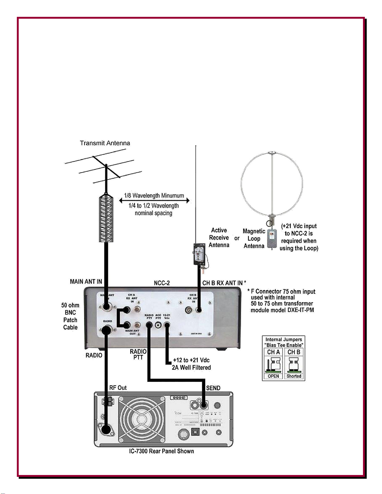
Interconnection Diagrams
Diagram 1 - Phasing a Transmit Antenna with a single Active Receive Antenna
using the RTR function
Diagram 1 shows connections for phasing a Transmit antenna signal with a single Active Receive
Antenna using the RTR function on a transceiver that does not have a RX ANT INPUT. When the
NCC-2 front panel RTR switch is in the Norm position, the RADIO is connected to listen to the
phasing of the MAIN ANT and the RX Antenna. The RTR switch position Main On, allows direct
listening of the MAIN ANT only.
Page 28

- 28 -
Diagram 2 - Phasing a Transmit Antenna with a single Active Receive Antenna
not using the RTR function
Diagram 2 shows connections for phasing a received signal from a transmit antenna signal that is
available at the RX ANT OUT of transceivers so equipped. NCC-2 front panel RTR switch is in the
Norm position for the RADIO to listen to the phased combination of the transmit antenna and the
CH A receive antenna. The RTR Main On is not used. The transceiver antenna switching is used to
change to listening to the transmit antenna.
Page 29

- 29 -
Diagram 3 - Phasing Two Active Receive Antennas not using the RTR function
Diagram 3 shows connections for two Active Receive Antennas not using the RTR Main Ant In.
Connections are direct phased receive antenna only, fed into RX ANT IN on the transceiver so
equipped. NCC-2 front panel switch is Norm position for RADIO to listen to phased combination.
RTR Main On is not used. The transceiver antenna switching is used to listen to the transmit
antenna.
Page 30

- 30 -
Diagram 4 - Phasing a Transmit Antenna with a single Active Receive Antenna
using the RTR function and sharing transmit signals with a SDR
Diagram 4 shows connections for phasing a Transmit Antenna with a single Active Receive
Antenna using the RTR function and sharing transmit signals with a second receiver. RX ANT IN
on transceiver is not used so that an external splitter can share transmit antenna signals with a
second receiver for SDR/panadapter display and NCC-2 CHA A RX ANT for simultaneous phased
reception on RADIO with the RTR switch in the Norm position. Toggling the RTR switch to Main
On cuts off the SDR receive and allows RADIO reception on MAIN ANT only. (DXE-KWD-RTR -
See Page 20)
Page 31

- 31 -
Diagram 5 - Phasing a Two Active Receive Antennas using the RTR function
and Amplifier
Diagram 5 shows the connections for a transceiver without RX ANT INPUT. The NCC-2 front
panel RTR switch is in the Norm position and connects RADIO to the phasing of only the receive
antennas. RTR switch to Main On allows direct listening of MAIN ANT only. Transceiver
amplifier keying line to RADIO PTT - RX ENABLE is passed through to ACC PTT with
Schottky diode protection for amplifier (RLY) relay keying connection.
Page 32
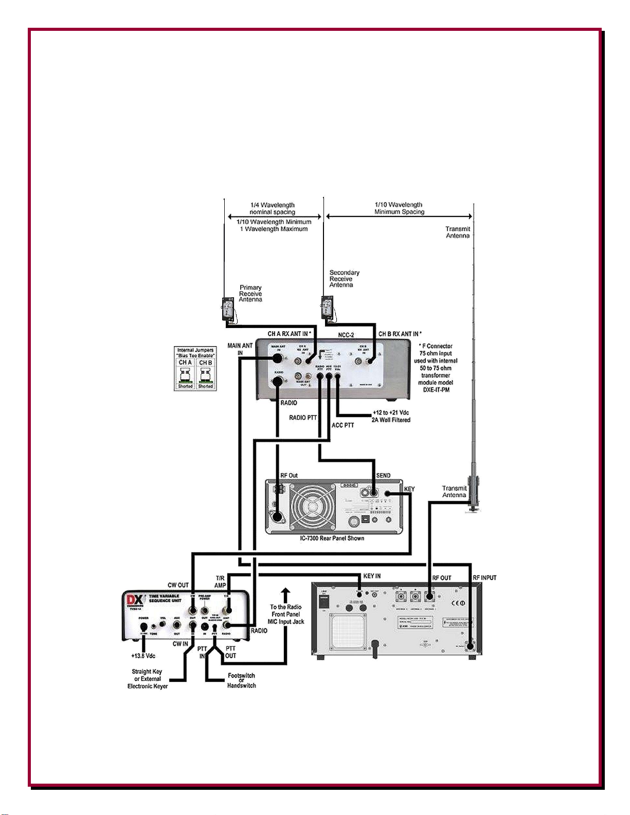
- 32 -
Diagram 6 - Phasing dual Active Receive Antennas on a system with a Transmit
Antenna, Sequencer and an Amplifier
Diagram 6 shows the DXE-NCC-2 for phasing two Active Receive Vertical antennas in a high
power transmit system using the RTR function on a transceiver that does not have an RX ANT
INPUT. The NCC-2 front panel RTR switch in the Norm position connects the RADIO to the
phasing of the two active receive antennas. The RTR switch position Main On allows direct
listening of MAIN ANT only.
Keying by the DXE-TVSU-1B Sequencer of the DXE-NCC-2 and the amplifier before keying the
radio provides appropriate timing delay to prevent the active antennas being damaged from transmit
RF. Refer to the DXE-TVSU-1B for more details.
Page 33
- 33 -
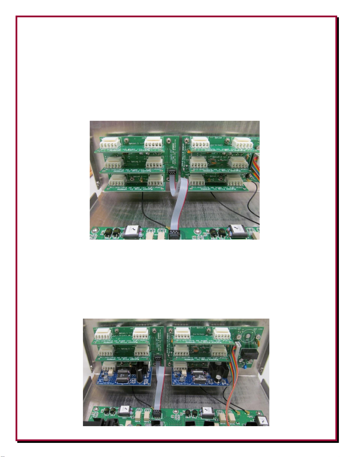
Appendix A
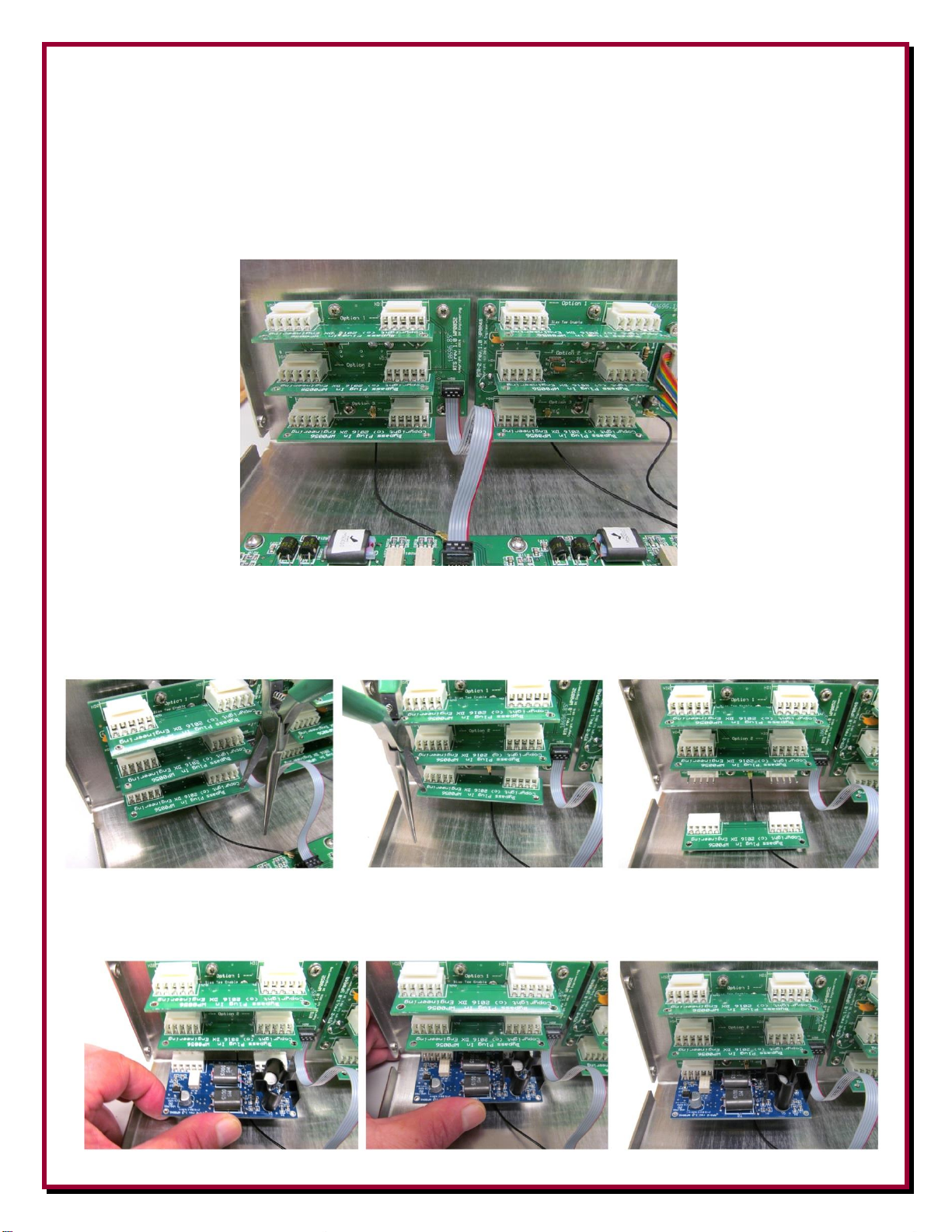
Internal Optional Modules
The NCC-2 has positions for optional modules (Receiver Guard, Pre Amp, 50-75 ohm Transformer)
for each RX ANT CH A and RX ANT CH B. Remove the cover from the NCC-2. Looking at the
rear of the unit from the inside, you will see the three Bypass Plug-In boards installed in each
channel as shown below. When an optional board or boards are not installed, the jumper boards
(labeled as “Bypass Plug In”) must be in place as shown below.
Option 1 - The Top position is where the 50-75 ohm Transformer Module DXE-IT-PM is installed.
Option 2 - The Middle position is where the Receiver Guard DXE-RG5000HD-PM is installed.
Option 3 - The Bottom position is where the Receive Preamplifier DXE-RPA-2-PM is installed.
Note: Because of the power and switching requirements, the Receive Preamplifier DXE-RPA-2-
PM must be installed in only the Bottom position.
The photo shown below shows two of the Receive Preamplifiers (DXE-RPA-2-PM) installed for
Channel A and Channel B.
Page 34
- 34 -
Removing - Installing Optional Modules or Bypass Plug-in Boards
The NCC-2 has Bypass Plug-In Boards installed at the factory. When installing the optional
modules, the Bypass Plug-In boards must be removed.
Remove the cover from the NCC-2. Looking at the rear of the unit from the inside, you will see the
three Bypass Plug-In boards installed in each channel as shown below.
To remove the Bypass Plug-In board, use one prong on a Needle Nose Plier. Put the prong through
the hole on the corner of the board to be removed and gently pry it slightly outward. Move the
prong to the other corner of the board to be removed and repeat the prying action. The board will
come loose from the board connectors and be able to be easily removed. See the photos below.
When installing the optional modules ensure the pins on both connectors are properly aligned and
push the optional module board completely in as shown below.
Page 35
- 35 -
Specifications
Useable Frequency Range: 300 kHz to 30 MHz
The NCC-2 is primarily designed for 500 kHz to 15 MHz use, although useful operating
range extends from below 300 kHz to above 30 MHz.
Third Order Output Intercept: +32 dBm each Input, +38 dBm both inputs combined
Gain Flatness: +/- 1 dB Over Complete Phase Rotation
Gain: Adjustable from 0 dB to –40 dB
Available Phase Rotation: >360 degrees
between 500 kHz and 15 MHz
Power : NCC-2 +13.8 Vdc 2A and accepts
well-filtered, +13.6 to +21 Vdc for normal
NCC-2 operation. Input DC line should be
fused at 3 amps to protect circuitry. (See text
for information about various input voltages
used with some active receive or loop
antennas).
Note: Every radio manufacturer's accessory interconnection scheme is different, you should consult
your radio manufacturer's manual for details and requirements for receive signal inputs/outputs and
switching voltages.
User Diagram
Use this page to draw in your set up for future reference.
Page 36

- 36 -
Technical Support
If you have questions about this product, or if you experience difficulties during the installation,
contact DX Engineering at (330) 572-3200. You can also e-mail us at:
DXEngineering@DXEngineering.com
For best service, please take a few minutes to review this manual before you call.
Manual Updates
Every effort is made to supply the latest manual revision with each product. Occasionally a manual
will be updated between the time your DX Engineering product is shipped and when you receive it.
Please check the DX Engineering web site (www.dxengineering.com) for the latest revision manual.
Warranty
All products manufactured by DX Engineering are warranted to be free from defects in material and workmanship for a
period of one (1) year from date of shipment. DX Engineering’s sole obligation under these warranties shall be to issue
credit, repair or replace any item or part thereof which is proved to be other than as warranted; no allowance shall be made
for any labor charges of Buyer for replacement of parts, adjustment or repairs, or any other work, unless such charges are
authorized in advance by DX Engineering.
If DX Engineering’s products are claimed to be defective in material or workmanship, DX Engineering shall, upon prompt
notice thereof, issue shipping instructions for return to DX Engineering (transportation-charges prepaid by Buyer). Every
such claim for breach of these warranties shall be deemed to be waived by Buyer unless made in writing. The above
warranties shall not extend to any products or parts thereof which have been subjected to any misuse or neglect, damaged
by accident, rendered defective by reason of improper installation, damaged from severe weather including floods, or
abnormal environmental conditions such as prolonged exposure to corrosives or power surges, or by the performance of
repairs or alterations outside of our plant, and shall not apply to any goods or parts thereof furnished by Buyer or acquired
from others at Buyer’s specifications. In addition, DX Engineering’s warranties do not extend to other equipment and
parts manufactured by others except to the extent of the original manufacturer’s warranty to DX Engineering.
The obligations under the foregoing warranties are limited to the precise terms thereof. These warranties provide exclusive
remedies, expressly in lieu of all other remedies including claims for special or consequential damages. SELLER
NEITHER MAKES NOR ASSUMES ANY OTHER WARRANTY WHATSOEVER, WHETHER EXPRESS,
STATUTORY, OR IMPLIED, INCLUDING WARRANTIES OF MERCHANTABILITY AND FITNESS, AND NO
PERSON IS AUTHORIZED TO ASSUME FOR DX ENGINEERING ANY OBLIGATION OR LIABILITY NOT
STRICTLY IN ACCORDANCE WITH THE FOREGOING.
©DX Engineering 2022
DX Engineering®, DXE®, DX Engineering, Inc.®, Hot Rodz®, Maxi-Core®, DX Engineering THUNDERBOLT®, DX
Engineering Yagi Mechanical®, EZ-BUILD®, TELREX®, Gorilla Grip® Stainless Steel Boom Clamps, Butternut®,
SkyHawk™, SkyLark™, SecureMount™, OMNI-TILT™, RF-PRO-1B®, AFHD-4® are trademarks of PDS Electronics,
Inc. No license to use or reproduce any of these trademarks or other trademarks is given or implied. All other brands
and product names are the trademarks of their respective owners.
Specifications subject to change without notice.
 Loading...