


Maxi-Core® 20
Baluns and Chokes
DXE-BAL-INS Rev 9a
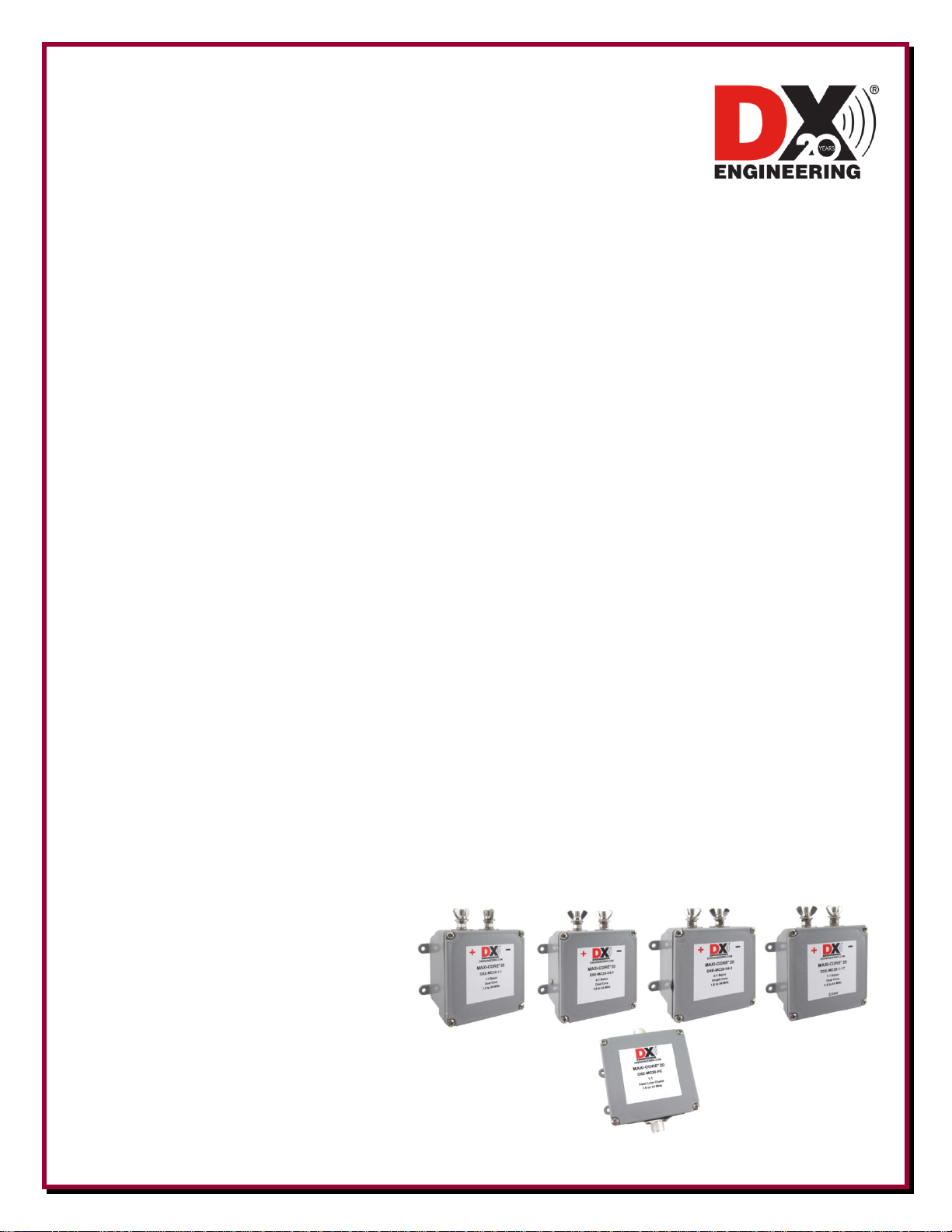
DXE-MC20-1-1 - 1:1 Ratio Current Choke Balun
DXE-MC20-1-1T - 1:1 Ratio Current Tuner Choke Balun
DXE-MC20-C4-1 - 4:1 Ratio Current Choke Balun
DXE-MC20-V4-1 - 1:1 Ratio Voltage Balun
DXE-MC20-FC - 1:1 Ratio Feedline Choke
© DX Engineering 2020
1200 Southeast Ave. - Tallmadge, OH 44278 USA
Phone: (800) 777-0703 ∙ Tech Support and International: (330) 572-3200
Fax: (330) 572-3279 ∙ E-mail: DXEngineering@DXEngineering.com
Introduction
The present-day DX Engineering was launched in the year 2000. To celebrate our
20th Anniversary in the year 2020 we have developed a new line of Baluns and
Feedline Chokes.
Introducing DX Engineering "Maxi-Core® 20" Baluns and Feedline Chokes.
Maxi-Core® 20 Baluns and Feedline Chokes reduce or eliminate currents on the outside of your feedline
allowing you to hear and to be heard much better. They keep more RFI/BCI out of your antenna and receiver
and transfer more of your transmitted signal to the antenna for higher efficiency, the best antenna pattern and
maximum performance.
Signaling a new era of RF performance across the 1.8 to 54 MHz frequency range, DX Engineering Maxi-
Core® 20 Baluns and Feedline Chokes handle full-legal-power-plus and provide higher common mode
impedance (CMI) across a greater frequency range than competing models and even previous DX
Engineering and Comtek models. Years of R&D coupled with major advancements in test equipment and
techniques combined with custom ferrite materials have allowed our engineering team to design the DX
Engineering Maxi-Core® 20 Baluns and Feedline Chokes.
Common mode impedance (CMI), also known as choking impedance, is a measure of how well a Balun or
Feedline Choke reduces exterior RF currents traveling through it and on the outside of the coaxial cable.
Currents that travel on the outside of the coax re-radiate signals directly to your antenna and then travel to
your receiver. Even with a Feedline Isolator (Choke) or Balun at the antenna end of the transmission line,
many times a Feedline Isolator is necessary at the transceiver side in order to squelch the noise currents
picked up by the feedline on the way to the radio.
Modern testing methods clearly show that coiled coax, sometimes known as an “ugly balun,” and
inexpensive baluns provide minimal CMI over just narrow frequency segments of the HF range.
Maxi-Core® 20 Baluns and Feedline Chokes have high CMI across the AM Broadcast band and the HF/6M
spectrum, which is essential to provide sufficient suppression of unwanted transmitted and received RFI/BCI
current on the feedline shield exterior.
Optional mounting brackets are available for use on wire antennas or for verticals, Yagi and beam antennas.
See the Suggested Parts tab after clicking "More Detail" on the DX Engineering web site on the model
Balun/Choke of interest. Each model listing provides additional specific information. Combination packages
that include balun or choke and bracket are also available.
Hear and be heard with DX Engineering Maxi-Core® 20 Baluns and Feedline Chokes!.
Optional mounting brackets are available
for use on wire antennas or for verticals,
Yagi and beam antennas. See the
Suggested Parts tab after clicking "More
Detail" on the DX Engineering web site
on the model Balun/Choke of interest.
Each model listing provides additional
specific information. Combination
packages that include balun or choke and
bracket are also available.
- 2 -

Features and benefits of Maxi-Core® 20 Baluns and Feedline Chokes:
Performance at the highest levels of efficiency in transmit or receive applications
Reduction or elimination of transmit RFI and receive noise
Currents on the feedline or antenna are forced equal for maximum efficiency and more symmetrical
antenna patterns
Weather resistant NEMA enclosure with convenient mounting holes
Four weep holes to help eliminate internal moisture
High Quality PTFE dielectric, Silver Plated SO-239 Connector
1/4-20 Stainless Steel Hardware
Choose superior performance from these models:
DXE-MC20-1-1 Maxi-Core® 20 - 1:1 Current Choke Balun - For all HF-6m balanced antennas with a
50 ohm feedpoint, including resonant dipoles, loops, Yagis, beams, etc.
DXE-MC20-1-1T Maxi-Core® 20 - 1:1 Current Choke Balun – This 1:1 "T" model is for force
feeding antennas with a tuner. Use it at the end of ladder line of any impedance or mounted on a coax fed
non-resonant antenna. This model tolerates operation at high SWR on non-resonant multi-band antennas.
Typically, for higher efficiency, this is the balun to use at the end of any impedance ladder line that is
feeding a non-resonant doublet. If higher losses are acceptable, it may be mounted on a coax fed antenna.
This model tolerates operation at high SWR on non-resonant multi-band antennas. But, in either case, not
all frequencies are available on a single dipole, as this is a choke balun, not a tuner.
DXE-MC20-C4-1 Maxi-Core® 20 - 4:1 Current Choke Balun is for use on antennas with a 200 ohm
feedpoint and on any impedance ladder line, especially antenna systems with higher impedance. This
model tolerates operation at high SWR on non-resonant multi-band antennas.
DXE-MC20-V4-1 Maxi-Core® 20 - 4:1 Voltage Balun is a 200 ohm to 50 ohm transformer for use on
random long-wire and OCF antenna applications. This true voltage balun is intentionally designed with
low CMI for antennas that need a transformer without RF choking for easier antenna tuner operation and
tolerates elevated SWR.
DXE-MC20-FC Maxi-Core® 20 - 1:1 Feedline Choke – This high CMI line isolator is perfect for use
in line on 50 ohm coaxial feedlines, at the antenna, tower or shack end of the feedline.
- 3 -

General Information on Baluns
Balun is an acronym for BALanced to UNbalanced, which describes certain circuit behavior in a
transmission line, source or load. Most communications applications deal with two-terminal sources,
transmission lines, and loads. This includes coaxial cables, open wire lines and systems working against
earth or a ground plane as the "second conductor".
The balun has to do a good job and be reliable. DX Engineering has the expertise to design and build a better
balun that will deliver more power to the antenna, be more reliable, and in many cases cost less than products
made by others.
We also realized that advertising hype over the years had confused the issue of just what type of balun was
appropriate to each antenna. This article is an attempt to define in simple terms how to get the most
performance from your system, both on receiving and transmitting.
There are two types of baluns: Current Baluns and Voltage Baluns.
Current Baluns
Current baluns (also known as choke baluns) allow the output voltage, with respect to "ground" or outside
world, to float to any value required to provide equal currents to each feedline conductor. In essence,
current baluns are a universal device which will be used to drive either balanced or unbalanced lines or
loads equally well. Current baluns isolate the device connected at one end from the device connected at the
other end. The balanced terminals on a current balun can be used to feed unbalanced or balanced loads or
lines equally well. They can also be used as broadband phase-invertors, baluns or ununs.
Voltage Baluns
Voltage baluns force the output terminals to equal voltages, which means currents can be far from even. A
voltage balun may allow feedline radiation (or reception) a good choice for off-center-fed antennas.
For most antennas, we recommend current baluns whenever possible. Current baluns provide better balance,
power handling, often have lower loss, and tolerate load impedance and balance variations.
Resonant Dipole Applications
A resonant dipole is cut for a particular band and its planned use is only within that band or on oddharmonics where the SWR is naturally low. The well known formula for the length of the element is in feet is
468/F. The ultimate length may vary a few percent either shorter or longer so better to make it a little longer
to start. The best balun for this application is the 1:1 ratio current balun, DXE-MC20-1-1 with the DXE-
WA-BMB.
This antenna can use a coax feed and the balun is usually located right at the dipole element to ensure that the
each side of the element receives equal currents and to keep currents off of the feedline. The feedline should
then be led away from the antenna at right angles which will keep the antenna field from introducing current
on the outside of the feedline after it leaves the balun and will keep the feedline from introducing noise onto
the antenna element.
Systems Requiring Antenna Tuners
Antenna systems requiring use of an antenna tuner for matching often have very high voltages or currents on
the transmission lines and baluns, even at modest power. In some cases, coax is used to connect the tuner
directly to the antenna. The feedline is connected to a coaxial connector on the tuner, and the tuner "matches"
the poor SWR of the antenna system to the station equipment. The feedline beyond the tuner still has very
high voltage, current and loss, even if the tuner input is matched to 50 Ω.
- 4 -

In other cases, the antenna feedline is balanced, and the tuner has an internal or external balun.
Unfortunately, most of the internal tuner baluns are 4:1 voltage baluns, which we will see is a poor choice.
Less often, balanced tuners are used. Such tuners, while often better at power handling than the more
common but less robust "T" network tuners, may still not provide the best transmission-line balance. They
would have to be ground independent; otherwise, they are the resonant equivalent of a voltage balun.
There are four areas of concern in such systems:
1. In a multi-band system, the antenna almost never presents a uniform load to the balun. As the
operating frequency changes, the balun load impedance can change from several thousand ohms to a
few ohms.
2. Most antenna tuners work best into high impedances, rather than low impedances. Most baluns inside
antenna tuners step the antenna impedance down. The tuner would actually work better if the balun
simply passed the line impedance through without stepping it down.
3. 4:1 Baluns inside antenna tuners, which are usually voltage-type baluns, are very poor performers
when presented with mismatched loads. 1:1 baluns are generally much more efficient and have a wider
operating impedance range.
4. Voltage baluns have restricted frequency response. The "good performance" frequency range is much
narrower in voltage baluns than in equivalent current-type baluns.
DX Engineering Tuner Balun
DXE-MC20-1-1T Maxi-Core® 20 - 1:1 Current Choke Balun – This 1:1 "T" model is for force feeding
antennas with a tuner. Use it at the end of ladder line of any impedance or mounted on a coax fed nonresonant antenna. This model tolerates operation at high SWR on non-resonant multi-band antennas.
Typically, for higher efficiency, this is the balun to use at the end of any impedance ladder line that is
feeding a non-resonant doublet. If higher losses are acceptable, it may be mounted on a coax fed antenna.
This model tolerates operation at high SWR on non-resonant multi-band antennas. But, in either case, not all
frequencies are available on a single dipole, as this is a choke balun, not a tuner.
DX Engineering Baluns
DX Engineering Maxi-Core® 20 BALUN technology allows your antenna perform to its fullest potential. DX
Engineering Maxi-Core® 20 baluns will deliver the power to your antenna with minimum loss and perform a
perfect transition from balanced to unbalanced. This will provide the strongest signal that your antenna is capable
of producing consistently with the lowest SWR under given conditions. These baluns exhibit a greater CMI over a
wide frequency range than conventional baluns. More energy goes to your antenna and high efficiency is achieved
over the entire frequency range.
- 5 -

Balun / Choke Selection Chart
Antenna Types
Suggested Balun/Choke
MC20-1-1
MC20-1-1T
MC20-C4-1
DXE-MC20-V4-1
MC20-FC
Dipole, coax fed, resonant
X X X
Dipole, double extended
X X
Dipole, folded, 300 ohm feed
X X
Dipole, folded, coax fed, resonant
X X
Dipole, folded, multi-wire
X
Dipole, folded, non-resonant
X X X
Dipole, folded, two-wire
X X
Dipole, inverted “V”, non-resonant
X X
Dipole, inverted “V”, resonant
X X
Dipole, ladder line fed, non-resonant
X X
Dipole, linear load, ladder line fed
X X
Dipole, long, non-resonant
X X
Dipole, multi-band resonant
X X
Dipole, off-center fed (80/20 OCF)
X X
Dipole, snake type, ladder line fed
X X
Dipole, trap
X X X
Doublet, multi-band, ladder line fed
X X
Horizontal “V” doublet
X
Inverted “V”, coax fed, resonant
X X
Log periodic, 150-250 ohm feedpoint
X
Log periodic, 50 ohm, direct coax feed
X
Long wire with ground system
X X
Loop, horizontal, coax fed
X
Loop, horizontal, non-resonant
X X
Loop, vertical, non-resonant
X
Loop, vertical, resonant, coax feed
X X X
Multi-band, ladder line fed
X X
Multi-band, remote balun
X X
Windom, balanced feed
X
Windom, conventional single wire
X
Yagi, 200 ohm feedpoint (KT-34, X-7)
X
Yagi, 50 ohm, direct coax feed
X X
Yagi, gamma matched
X X
Yagi, hairpin/beta matched
X X X
Yagi, trap tri-bander
X X X
Note: A balun mounting bracket is required to take the strain off of the balun terminals.
DX Engineering has various balun mounting brackets available.
- 6 -

Connections
Both balanced terminals are effectively floating, or ground independent, over the operating frequency of
the balun. The balanced terminals do have a phase relationship with the unbalanced coax connector. The
RED “D” in DX Engineering on the balun label is adjacent to the positive phase terminal as shown below. In
some applications, such as resonant or trapped dipoles and Yagis, the phase is not important. Other
applications, such as single-wire-fed antennas, require the antenna system ground to be attached to the
negative phase terminal. When tightening the wing nuts. Use an open end wrench in the hex nut close to the
balun body to endure the terminals do not rotate.
Balun Used With Single-Wire Feed
Note: The RED
terminal is the Negative Phase Terminal. Both terminals must be used for balanced or unbalanced
lines or loads. The BLACK
unbalanced coax connection.
D
in the DX Engineering logo is closest to the Positive Phase Terminal. The other
X
is the Negative Phase Terminal and is on the shield side of the
Installation
While the installation of this balun is a simple process, there are a multitude of factors to consider when
designing and erecting antenna systems. The antenna mounting height, proximity to structures, the feedline
type, length and velocity factor are all factors that affect antenna performance. Note: Balun mounting
brackets are required to help keep the terminals and wire connections from having too much strain on them.
Mounting
All DX Engineering baluns are manufactured with a NEMA standard enclosure. Note: Balun mounting
brackets are required to help keep the connections from getting too much strain on them.
Manual Updates and Information
Every effort is made to supply the latest manual revision with each product. Occasionally a manual will be
updated between the time your DX Engineering product is shipped and when you receive it. Please check the
DX Engineering web site (www.dxengineering.com) for the latest revision manual.
- 7 -

Technical Support
If you have questions about this product, or if you experience difficulties during the installation, contact DX
Engineering at (330) 572-3200.
You can also e-mail DX Engineering at: DXEngineering@DXEngineering.com
For best service, please take a few minutes to review this manual before you call.
Warranty
All products manufactured by DX Engineering are warranted to be free from defects in material and workmanship for a
period of one (1) year from date of shipment. DX Engineering’s sole obligation under these warranties shall be to issue
credit, repair or replace any item or part thereof which is proved to be other than as warranted; no allowance shall be
made for any labor charges of Buyer for replacement of parts, adjustment or repairs, or any other work, unless such
charges are authorized in advance by DX Engineering. If DX Engineering’s products are claimed to be defective in
material or workmanship, DX Engineering shall, upon prompt notice thereof, issue shipping instructions for return to
DX Engineering (transportation-charges prepaid by Buyer). Every such claim for breach of these warranties shall be
deemed to be waived by Buyer unless made in writing. The above warranties shall not extend to any products or parts
thereof which have been subjected to any misuse or neglect, damaged by accident, rendered defective by reason of
improper installation, damaged from severe weather including floods, or abnormal environmental conditions such as
prolonged exposure to corrosives or power surges, or by the performance of repairs or alterations outside of our plant,
and shall not apply to any goods or parts thereof furnished by Buyer or acquired from others at Buyer’s specifications.
In addition, DX Engineering’s warranties do not extend to other equipment and parts manufactured by others except to
the extent of the original manufacturer’s warranty to DX Engineering. The obligations under the foregoing warranties
are limited to the precise terms thereof. These warranties provide exclusive remedies, expressly in lieu of all other
remedies including claims for special or consequential damages. SELLER NEITHER MAKES NOR ASSUMES ANY
OTHER WARRANTY WHATSOEVER, WHETHER EXPRESS, STATUTORY, OR IMPLIED, INCLUDING
WARRANTIES OF MERCHANTABILITY AND FITNESS, AND NO PERSON IS AUTHORIZED TO ASSUME
FOR DX ENGINEERING ANY OBLIGATION OR LIABILITY NOT STRICTLY IN ACCORDANCE WITH THE
FOREGOING.
©DX Engineering 2020
DX Engineering®, DXE®, DX Engineering, Inc.®, Hot Rodz®, Maxi-Core®, DX Engineering THUNDERBOLT®, DX
Engineering Yagi Mechanical®, EZ-BUILD®, TELREX®, Gorilla Grip® Stainless Steel Boom Clamps, Butternut®,
SkyHawk™, SkyLark™, SecureMount™, OMNI-TILT™, RF-PRO-1B®, AFHD-4® are trademarks of PDS Electronics,
Inc. No license to use or reproduce any of these trademarks or other trademarks is given or implied. All other brands
and product names are the trademarks of their respective owners.
Specifications subject to change without notice.
- 8 -
 Loading...