


Remote Tuner Options
for the
DXE-MBVE-5A
Vertical Antenna
DXE-MBVE-5UGBRT3
for the
MFJ-993BRT 300 Watt Remote Tuner
DXE-MBVE-5UGBRT4
for the
MFJ-994BRT 600 Watt Remote Tuner
DXE-MBVE-5UGBRT3-4- INS-Revision 0b
Remote Tuner shown with additional optional parts
© DX Engineering 2017
1200 Southeast Ave. - Tallmadge, OH 44278 USA
Phone: (800) 777-0703 ∙ Tech Support and International: (330) 572-3200
Fax: (330) 572-3279 ∙ E-mail: DXEngineering@DXEngineering.com
Introduction
DX Engineering
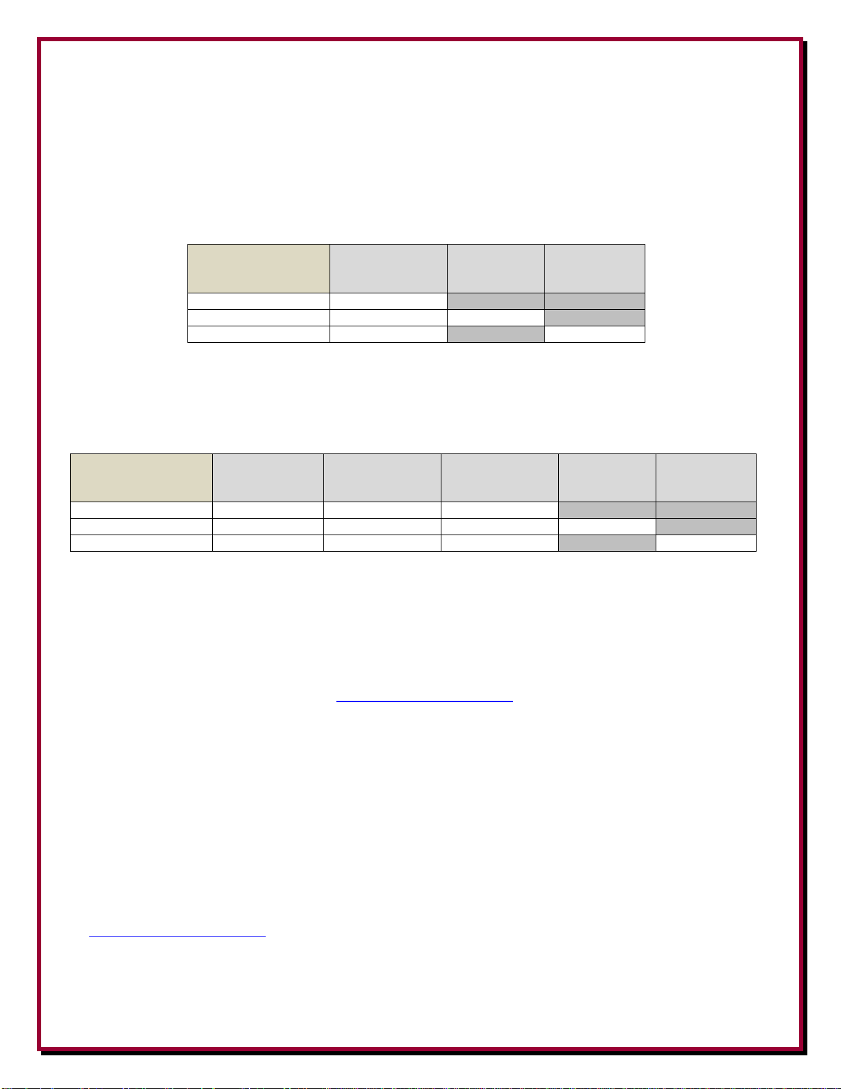
Antenna Model
Numbers
MFJ-993/4BRT -
Brackets
MFJ-993BRT -
Tuner
300 Watt
MFJ-994BRT -
Tuner
600 Watt
DXE-MBVE-5AE-BRT
X
DXE-MBVE-5AEBRT3
X X
DXE-MBVE-5AEBRT4
X X
DX Engineering
Upgrade Model
Numbers
DXE-MBVE-THW
Hardware Kit
DXE-MBVE-5A-
UGHW
Hardware Kit
MFJ-993/4BRT -
Brackets
MFJ-993BRT -
Tuner
300 Watt
MFJ-994BRT -
Tuner
600 Watt
DXE-MBVE-5UG-BRT
X X X
DXE-MBVE-5UGBRT3
X X X X
DXE-MBVE-5UGBRT4
X X X X
This instruction manual describes three of the optional remote tuner upgrade packages available for
the DXE-MBVE-5A multi-band vertical antenna system.
There are 3 complete DXE-MBVE-5A antenna systems for use with either the MFJ-993BRT or
MFJ-994BRT Remote Tuner. These packages include the DXE-MBVE-5A antenna.
X = Included
There are two upgrade retrofit kits for existing DXE-MBVE-5/5A systems for use with either the
MFJ-993BRT or MFJ-994BRT Remote Tuner. There is also one upgrade kit that has the hardware
needed to mount the MFJ-998RT Remote Tuner that the customer already has.
X = Included
There are also options available for other MFJ remote tuners allowing operation at 200, 300, 600 or
1500 Watt power levels. See the DX Engineering web site for complete details.
A complete manual including the assembly of the DXE-MBVE-5A antenna system that also
includes the information in this manual is available from DX Engineering and can be downloaded
from the DX Engineering web site at www.DXEngineering.com
Additional Material Needed but not Supplied:
JTL-12555 Jet-Lube™ SS-30 Pure Copper Anti-Seize 12555 - To ensure good electrical
and RF connection for Aluminum Element Sections and also used on the threads of Stainless
Steel Hardware to prevent galling (seizing) and aid in proper tightening.
The assemblies or upgrades that use the extended base tube and new base tube insulator are
basically built the same as the standard DXE-MBVE-5A which is described in greater detail in the
DXE-MBVE-5A manual which is available on-line from the DX Engineering web site at
www.DXEngineering.com. The Saf-T-Tilt™ base and the aluminum vertical elements are all the
same for all of the DXE-MBVE-5A models. The only difference is the base tube length (Short Base
tube is 14”, Long Base Tube required for the remote tuners is 36”) new base tube insulator and
associated hardware.
- 1 -

Upgrade Hardware for the
SAF-T-Tilt™ Base Assembly Upgrade Hardware Kit
DXE-MBVE-5A-UGHW for the extended base tube option
Qty
Drawing
Ref.
Number
1/4”-20 x 3/4” long Hex Head Bolt, Stainless Steel
1 18
1/4”-20 x 2-3/4” long Hex Head Cap Screw, Stainless Steel
1
23
1/4”-20 x 3-1/4” long Hex Head Cap Screw, Stainless Steel
2
17
1/4” Flat Washer, Stainless Steel
11
19
1/4” Split Lock Washer, Stainless Steel
6
20
1/4" External Tooth Washer, Stainless Steel
3
21
1/4”-20 Hex Nut, Stainless Steel
6
22
1/4”-20 x 3” long Hex Head Cap Screw, Stainless Steel
2
25
1/2”-13 Hex Nut, Stainless Steel
1
11
1/2”-13 x 4-1/2” long, Hex Head Bolt, Stainless Steel
2
12
1/2” Flat Washer, Stainless Steel, Thick
1
13
1/2” External Tooth Washer, Stainless Steel
2
14
1/2” Split Lock Washer, Stainless Steel
1
15
1/2”-13 Flanged Nut, Stainless Steel
1
16
7” Wire, 14 ga PVC insulated, two 1/4” Ring Terminals
1
24
Extended Base Tube Drawing
This drawing shows
the Upgrade
Hardware Kit that
includes the associated
hardware.
For existing systems,
the new hardware is
supplied with the
upgrade kits to make
installation easier.
NOTE: The Upgrade
Kits also include an
extended (36”) Base
Tube and a new
Drilled Insulator
- 2 -

DXE-MBVE-THW Parts Listing
DXE-MBVE-THW Mounting Hardware Kit
For the MFJ-993BRT/MFJ-994BRT Tuner mounting option
Qty
U-Bolt, Stainless Steel, 2.5”, 4” long, 5/16”-18 threads
2
Aluminum Saddle, V-Block
2
5/16”-18 Hex Nut, Stainless Steel
9
5/16”-18 x 5/8” long, Hex Head Cap Bolt, Stainless Steel
1
5/16” Washer, Flat, Stainless Steel
9
5/16” Washer, External Tooth, Stainless Steel
5
5/16” Washer, Split Lock, Stainless Steel
9
2” Element Clamp with Threaded Stud, Stainless Steel
1
10-24, Hex Nut, Stainless Steel
1
#10 Washer, Split Lock, Stainless Steel
1
#10 Washer, Flat, Stainless Steel, Thick
2
#10 Washer, External Tooth, Stainless Steel
1
3” Wire Assembly, 12 ga, Black Insulated, two ring terminals
1
10” Wire Assembly, 12 ga, Black Insulated, two #10 ring terminals
1
Installing the MFJ-993BRT or MFJ-994BRT option
1. Install the short ground wire in the corner hole
on the tuner mounting flange using the 5/16”-18
Hex Nut, 5/16”-18 x 5/8” long Hex Head Cap
Bolt, 5/16” Flat Washer, 5/16” External Tooth
Washer, 5/16” Split Lock Washer and 3” Wire
Assembly. The other end of the short 3” tuner
wire goes to the tuner ground wing nut
connection on the tuner as shown.
2. Position one of the tuner mounting aluminum V-saddle
clamps 3/4” below the top of the thick wall tube as
shown. Refer to the photos on Page 36 for the positioning
of the clamps in as compared to the antenna base.
Use two 5/16”-18 Hex Nuts, two 5/16” Flat Washers, two
5/16” Split Lock Washers and one 5/16”-18 x 4” long UBolt. Do not over tighten the U-Bolt Hex Nuts which can
break or bend the aluminum V-saddle clamp. Evenly
tighten each side of the U-bolt until the split lock washer
is seated properly.
- 3 -

3. Loosely mount the bottom aluminum saddle clamp
assembly approximately 13-1/4” below the previously
(upper) mounted saddle clamp using the same hardware
described for the upper clamp. Ensure both clamps are
facing the same direction.
(This installation method works well since the MFJ
tuner mounting flanges can be in slightly different
positions on the tuners.)
4. Place on 5/16” External Tooth Washer on each leg of the upper saddle clamp U-bolt and then
position the MFJ-993BRT or MFJ-994BRT tuner in place on the upper U-bolt that protrudes
from the saddle clamp. Once in place, loosely install the two 5/16” Flat Washers, two 5/16” Split
Lock Washers and two 5/16”-18 Hex Nuts to hold the tuner in place on the upper clamp as
shown. You want the tuner to be able to move a bit for final positioning.
5. Position the lower saddle clamp (with the external tooth
washers on each leg) so the U-bolt will pass through the
bottom mounting flange on the tuner as shown. Once the
tuner is positioned in place and straight - use the two 5/16”
Flat Washers, two 5/16” Split Lock Washers and two 5/16”18 Hex Nuts to hold the bottom of the tuner in place.
Tighten all of the tuner mounting hardware (top and
bottom).
- 4 -

6. When the upper antenna parts are mounted to the base assembly (see previous installation
instructions), install the Studded Band Clamp on the first element just above the black insulator
with the stud facing the side nearest the tuner connections. Install the 10” long tuner wire on the
studded band clamp using the #10 hardware as shown. The other end of the 10” wire is
connected to the tuner output wing nut connection on the tuner as shown.
The feedline coaxial cable connects from the Antenna Tuner to the Bias-T in the radio room.
Two views showing the
MFJ-993BRT or MFJ-994BRT
installed on the
DXE-MBVE-5A antenna
- 5 -

Bias Tee Information
The MFJ-4117 Bias Tee is included with the MFJ Remote Tuner. Since the
coaxial cable is supplying the DC voltage to the remote tuner (injected in the
coaxial cable by the Bias Tee), the coaxial cable used must have a good DC
path. Lightning protectors that block DC cannot be used.
Follow the instructions provided by MFJ for both the Tuner and the Bias
Tee.
Make certain the coaxial cables are properly connected to the Bias "T" as shown. Ensure the
ON/OFF switch on the Bias "T" is turned ON when using the system.
NOTE: Review the MFJ Remote IntelliTuner™ manual for a detailed
explanation of the Remote IntelliTuner™ and the Bias Tee operation.
Installing the Bias Tee incorrectly may cause damage to your radio.
- 6 -

Technical Support
If you have questions about this product, or if you experience difficulties during the installation,
contact DX Engineering at (330) 572-3200. You can also e-mail us at:
DXEngineering@DXEngineering.com
For best service, please take a few minutes to review this manual before you call.
Manual Updates
Every effort is made to supply the latest manual revision with each product. Occasionally a manual
will be updated between the time your DX Engineering product is shipped and when you receive it.
Please check the DX Engineering web site (www.dxengineering.com) for the latest revision manual.
Warranty
All products manufactured by DX Engineering are warranted to be free from defects in material and workmanship for a
period of one (1) year from date of shipment. DX Engineering’s sole obligation under these warranties shall be to issue
credit, repair or replace any item or part thereof which is proved to be other than as warranted; no allowance shall be
made for any labor charges of Buyer for replacement of parts, adjustment or repairs, or any other work, unless such
charges are authorized in advance by DX Engineering. If DX Engineering’s products are claimed to be defective in
material or workmanship, DX Engineering shall, upon prompt notice thereof, issue shipping instructions for return to
DX Engineering (transportation-charges prepaid by Buyer). Every such claim for breach of these warranties shall be
deemed to be waived by Buyer unless made in writing. The above warranties shall not extend to any products or parts
thereof which have been subjected to any misuse or neglect, damaged by accident, rendered defective by reason of
improper installation, damaged from severe weather including floods, or abnormal environmental conditions such as
prolonged exposure to corrosives or power surges, or by the performance of repairs or alterations outside of our plant,
and shall not apply to any goods or parts thereof furnished by Buyer or acquired from others at Buyer’s specifications.
In addition, DX Engineering’s warranties do not extend to other equipment and parts manufactured by others except to
the extent of the original manufacturer’s warranty to DX Engineering. The obligations under the foregoing warranties
are limited to the precise terms thereof. These warranties provide exclusive remedies, expressly in lieu of all other
remedies including claims for special or consequential damages. SELLER NEITHER MAKES NOR ASSUMES ANY
OTHER WARRANTY WHATSOEVER, WHETHER EXPRESS, STATUTORY, OR IMPLIED, INCLUDING
WARRANTIES OF MERCHANTABILITY AND FITNESS, AND NO PERSON IS AUTHORIZED TO ASSUME
FOR DX ENGINEERING ANY OBLIGATION OR LIABILITY NOT STRICTLY IN ACCORDANCE WITH THE
FOREGOING.
©DX Engineering 2017
DX Engineering®, DXE®, DX Engineering, Inc.®, Hot Rodz®, Maxi-Core®, DX Engineering THUNDERBOLT®, DX
Engineering Yagi Mechanical®, EZ-BUILD®, TELREX®, Gorilla Grip® Stainless Steel Boom Clamps, Butternut®,
SkyHawk™, SkyLark™, SecureMount™, OMNI-TILT™, RF-PRO-1B®, AFHD-4® are trademarks of PDS Electronics,
Inc. No license to use or reproduce any of these trademarks or other trademarks is given or implied. All other brands
and product names are the trademarks of their respective owners.
Specifications subject to change without notice.
- 7 -
 Loading...