

Page 1

Feedline Voltage Coupler
DXE-FVC-1
DXE-FVC-1-INS Rev. 5b
© DX Engineering 2017
1200 Southeast Ave. - Tallmadge, OH USA
Phone: (800) 777-0703 ∙ Tech Support and International: (330) 572-3200
Fax: (330) 572-3279 ∙ E-mail: DXEngineering@DXEngineering.com
Page 2

Introduction
The DXE-FVC-1 Feedpoint Voltage Coupler is a versatile receive feedline or control cable voltage
injector and switching interface. It is used to control receive antenna switching devices through the
feedline or on a two conductor control cable.
The DXE-FVC-1 converts 12 Vac voltage input to fuse-protected 0V, +12 Vdc, −12 Vdc and 12
Vac output voltages. The voltage output of the DXE-FVC-1 is simultaneously sent on the receive
feedline through the ANT port F connector and on the OUT pin of the removable 5-terminal rearpanel connector for use with a two-conductor control cable. This voltage sequence can be used to
provide 4-direction switching of an antenna array or selection of four different antennas.
Connection of the DXE-FVC-1 to the radio equipment receive antenna input may be made using
either the standard RCA phono -or- the type F connector. This allows use of readily available RF
compatible RCA phono patch cords or 75 Ω coaxial cable and connectors, and protects the receive
system from accidental connection to transmitting equipment.
As supplied, the DXE-FVC-1 input is ready to be voltage switched using the DX Engineering
DXE-CC-8A Control Console, 8 Position Switch. Alternatively, the user may choose to use a rotary
switch by changing an internal jumper in the DXE-FVC-1 to use input grounding switching control.
Features
External 12 Vac heavy duty power transformer included
Metal housing – superior shielding, rugged, easy mounting
Convenient installation – mounts anywhere in your shack
Rugged control connector – removable, reliable solder-less connections
Receive only connectors, Type F and RCA phono - used to protect receive equipment
Internal thermal reset fuse − full protection against accidental shorts
Flexible input − BCD voltage or 1-of-4 ground switching
Dual LEDs − show control voltage output, used for directional indicators
2
Page 3

Connections & LEDs
#
Label Designation
Description
1
12 VAC IN
Standard 2.1 mm connector for 12 Vac input
Included with the DXE-FVC-1 is a 12 Vac wall transformer
2
OUT-AC-NEG-POS-GND
Removable control cable input connector
3
ANT
F Connector for 75-ohm coaxial cable from the
DXE-FVC-1 connection to receive antenna system
4
RADIO
F connector for connection of 75-ohm coaxial cable from the
DXE-FVC-1 to the customer's Radio Receive Input
5
RCA phono plug for connection from DXE-FVC-1 to the
customer's Radio Receive Input
6 & 7
- AC +
●●
Red LED - when lit it indicates that +12 Vdc is being sent
out through the ANT connection
Green LED - when lit it indicates that -12 Vdc is being sent
out through the ANT connection
Red and Green LED - when both are lit, they indicate 12
Vac is being sent out through the ANT connection
When both the Red and Green LED's are not lit, 0 v is
applied to the ANT connector
●●
●●
●●
3
Page 4

NOTE: The DXE-FVC-1 uses 1/2-wave rectification for the DC control voltages. When
measuring the output using an RMS or average reading DVM, the normal DC output of
the DXE-FVC-1 will indicate a nominal +/– 6 Volts. The AC voltage will measure 12 Vac.
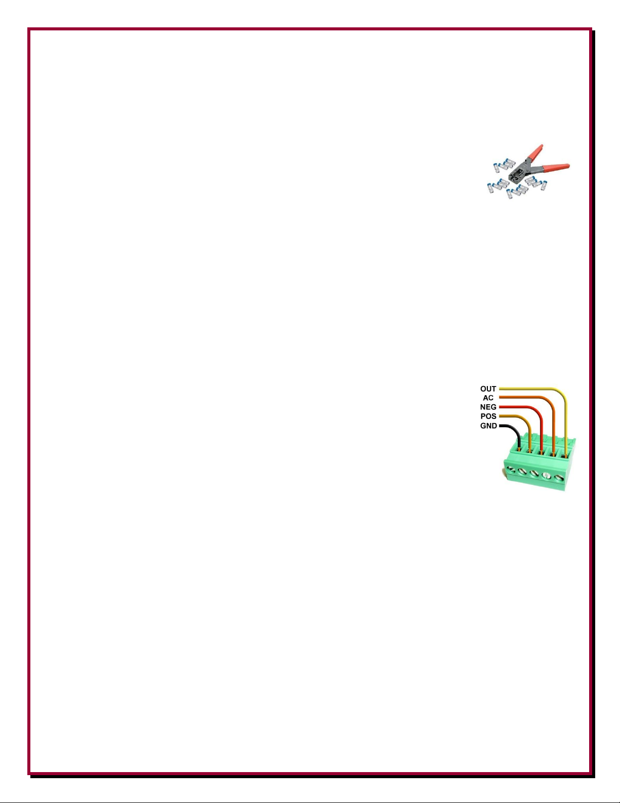
Figure 1 - DXE-FVC-1 removable connector
The green connector on the rear of the DXE-FVC-1 is a two part polarized connector. This
connector, for the control wires, is removed by pulling it straight off. This will allow easy wire
placement or servicing as needed. When pushing the connector back in place, ensure you press
straight inward. Refer to Figure 1.
Connections are made with a screwdriver; no soldering is required. Do not attempt to solder wires
to the connector, and do not over-tighten the screws. Remove 1/4 inch of insulation from each
control wire so the screw terminals tighten on the wire and not the insulation. This will also protect
adjacent wires from the potential of shorting together. Stranded wire should be tightly twisted or
very lightly tinned before insertion. Open terminal slots by turning the screws CCW (counter clockwise) before wire ends are inserted. Do not force the screw beyond the stop.
Connecting the DXE-FVC-1 to a receive antenna system uses a standard type F connector. This
allows use of readily available 75-ohm coaxial cable and connectors, and protects the receive
system from accidental connection to transmitting equipment.
Installation
The DXE-FVC-1 is typically mounted near the operating position so the LEDs are visible, but any
protected location with ambient temperatures below 150° F non-condensing (65° C) is acceptable.
The DXE-FVC-1 unit requires 12 Volts AC power. The unit will not
function properly if 12 Vdc is used on the input. The included wall
transformer will provide 12 Volts AC power for the DXE-FVC-1.
A malfunction will occur if 12 Vdc is used to power the DXE-FVC-1.
Figure 2 - Transformer Label
The switched output voltages appear simultaneously on both the ANT feedline connector and the
rear panel OUT terminal on the 5 position green connector. The OUT terminal is used for
supplemental switching control output only and cannot be used to provide power to any unit.
4
Page 5

Internal Jumper Settings
Note: The DXE-FVC-1 must be powered by 12 Vac in order to operate no matter which
way JMP1 is set.
Internal jumper JMP1 is used to select the input control function that controls the DXE-FVC-1.
Remove the four screws holding the cover to the base to gain access to the internal jumper.
Figure 3 - 4 screws that hold the DXE-FVC-1 case together
The factory default setting has the jumper JMP1 connecting
to the two pins below EXT.
Figure 4 - Factory default setting for JMP1
When JMP1 is set to EXT, external +12 Vdc (nominal) is required for BCD input switching control.
The default jumper position, EXT, sets the DXE-FVC-1 to respond to external source voltages of
+9 to +15 Vdc in order to control the output voltages. The DXE-CC-8A Control Console provides
these voltages.
If you wish to use a simple switch closure to ground on the input in order to control the output, then
change the jumper setting to INT. Control current is low (less than 100 mA). With JMP1 set to INT,
the DXE-FVC-1 internally sources the control voltage. This allows using a 1-of-4 input switching
control scheme by grounding the appropriate input pin, which selects the desired output. Switching
can be accomplished with a simple, inexpensive SP4T rotary switch or a push-button switch
arrangement.
BCD control interface systems require a 3-conductor control cable. 1-of-4 logic requires a 4conductor control cable. Use of the supplemental control OUT output would require a 2-conductor
cable. These conductor counts include the ground return.
5
Page 6
Connections
DXE-F6-SPL or DXE-F6-1000 high quality 75-ohm “flooded” RG-6 type coaxial cable is
recommended. Flooded style cables have the distinct advantage of automatically sealing small
accidental cuts or lacerations on the jacket. Flooding also prevents shield contamination and the
coaxial cable can be direct-buried. Moisture coming into the shield often occurs at
the connector and can cause increased system noise. For superior watertight
connections, use DXE-SNS6-25 Snap-N-Seal connectors. Weather-tight Snap-NSeal connectors CANNOT be installed with normal crimping tools or pliers. The use
of the DXE-SNS-CT1 installation tool is available from DX Engineering.
The F type ANT connector on the DXE-FVC-1 is used to connect the receiving antenna feedline.
The appropriate switching voltage is applied through the feedline by the DXE-FVC-1. It is critical
that the feedline connectors remain dry and you do not place any intentional DC shorts or opens on
the feedline between the DXE-FVC-1 and anything being controlled. This includes lightning
arrestors, splitters or any other accessory not intended for feedlines carrying power or control
voltages. The radio connections go to the receiver using either the type F or RCA phono connector.
The DXE-FVC-1 requires 12 Vac to operate. Connect the included wall transformer to the 2.1 mm
barrel plug on the DXE-FVC-1 labeled "12 VAC IN" .
Control connections for the DXE-FVC-1 labeled AC, NEG, POS and GND as well as the
supplemental output labeled OUT are made at the removable, green 5-terminal
screw-type connector. Do not attempt to solder wires to this connector. Remove
1/4 inch of insulation from each 16 to 24 gauge control wire, insert the wires in the
appropriate screw terminal. When tightening ensure the connection is secure
against the wire and not the insulation. Be certain that adjacent wires are
positioned to eliminate the possibility of shorting. Stranded wire should be tightly
twisted or very lightly tinned before insertion. Open terminal slots on the
removable green connector by turning the screws counter clock-wise before the
wire ends are inserted. Do not force the screw beyond the stop. Tighten each
screw securely clock-wise without over-tightening.
The example above
Note: The ground connection (GND) uses color coded
should be connected to your station ground buss. wire. Your wire
may not look the same
Input/Output Logic and Connection Examples
The DXE-CC-8A Control Console may be used to provide the voltage or a user supplied switch
may be used to provide the voltage or grounding, required by the DXE-FVC-1 input in order to
control the output. The following tables show the input and output combinations for both schemes.
Each input state results in a different output voltage thru the ANT type F-connector and on the OUT
supplemental terminal per Table 1. Note the LED indications.
6
Page 7

Application Notes
NOTE: The DXE-FVC-1 uses 1/2-wave rectification for the DC control voltages. When
measuring the output using an RMS or average reading DVM, the normal DC output of
the DXE-FVC-1 will indicate a nominal +/– 6 Volts. The AC voltage will measure 12 Vac.
DXE-CC-8A
or user +12
Vdc switch
position
+ 12 Vdc
applied to
DXE-FVC-1
POS terminal
+ 12 Vdc
applied to
DXE-FVC-1
NEG terminal
DXE-FVC-1
Voltage
Output
LED On
1 0 0
0 V
●
Neither
●
2
0
+12 Vdc
-12 Vdc
●
Green
●
3
+12 Vdc
0
+12 Vdc
●
Red
●
4
+12 Vdc
+12 Vdc
12 Vac
●
Both
●
The following tables and diagrams depict the wiring logic of the most common use of the DXEFVC-1 Feedline Voltage Coupler controlling the DXE-RBS-1P Reversible Beverage System.
These connections apply to the configurations examples in Figures 5, 6, 9, and 10.
When using the DXE-FVC-1 Feedline Voltage Coupler with the DXE-RFS-2P Receive Four
Square System and some DXE-RLS-2 Two Port Receive Antenna Switch configurations, a polarity
reversal is required. This is accomplished by swapping the POSitive and NEGative wires on the
DXE-FVC-1 unit for the configuration examples in Figures 7, 8 and 11. The polarity information is
clearly noted on each diagram in the small tables labeled "Control Cable Wiring".
BCD Logic
As shipped, with the internal JMP1 set to EXT, a BCD logic uses an external +12 Vdc to switch the
DXE-FVC-1 input in order to control the output. The DXE-CC-8A Control Console supplies the
external voltage, referenced to the GND terminal. The wiring from the DXE-CC-8A to the DXE-
FVC-1 input according to Table 1 is shown below using COM-CW3 three conductor cable.
BCD input voltage control uses only the terminals labeled POS, NEG and GND. There are four
possible states for switching. Note: Logic zero is all terminals open or floating.
Table 1 Default BCD Logic Input and
Resulting Output
The above diagram is the most
common hook up scheme.
Refer to Figures 5, 6, 9 and 10
7
Page 8
One of Four Grounding Logic
User
switch
position
Ground
applied to
DXE-FVC-1
POS terminal
Ground
applied to
DXE-FVC-1
NEG terminal
Ground
applied to
DXE-FVC-1
AC terminal
DXE-FVC-1
Voltage
Output
LED On
1
N/C
N/C
N/C
0 V
●
Neither
●
2
N/C
GND
N/C
-12 Vdc
●
Green
●
3
GND
N/C
N/C
+12 Vdc
●
Red
●
4
N/C
N/C
GND
12 Vac
●
Both
●
NOTE: The DXE-FVC-1 uses 1/2-wave rectification for the DC control voltages. When
measuring the output using an RMS or average reading DVM, the normal DC output of
the DXE-FVC-1 will indicate a nominal +/– 6 Volts. The AC voltage will measure 12 Vac.
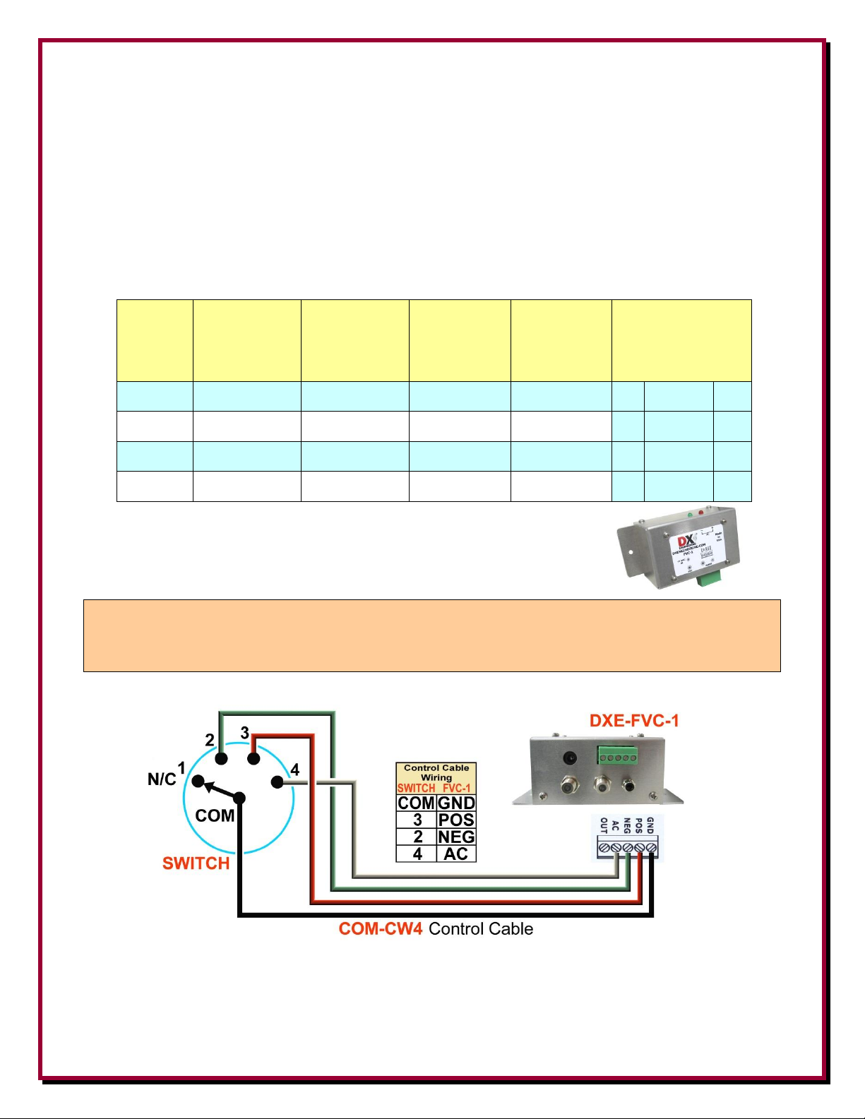
Alternatively, after changing the internal jumper JMP1 to INT, a customer supplied 1-of-4
grounding switch may be wired to the DXE-FVC-1 input according to Table 3. Grounding the
appropriate terminal(s) results in a different output voltage through the ANT type F-connector and
on the green connector OUT terminal. Control using a 1-of-4 grounding control uses terminals POS,
NEG, AC and GND
Note the LED indications. GND signifies a grounding of the respective terminal. N/C is No
Connection or floating. COM is the common terminal on the 4 position switch.
Table 3 1-of-4 Grounding
Logic and Resulting Output
The above diagram is the 1 of 4 grounding logic hook up scheme using
a customer supplied 4 position switch.
8
Page 9

Maintenance
Figure
Description
5
Depicts a typical DXE-RBSA-1P Reversible Beverage System layout
6
Shows a Four-Direction Beverage System using two DXE-RBSA-1P Reversible
Beverage Systems.
7
Describes a DXE-RFS-TS2P Complete Receive Four Square Array Package.
8
Uses a DXE-FVC-1 Feedline Voltage Coupler to supply the switching voltages for a
system that has four different receive inputs using the DXE-RLS-2 Two Port Receive
Antenna Switches.
9
Has the DXE-FVC-1 Feedline Voltage Coupler providing the control voltages for a
Single Transmit Antenna System using a DXE-RBS-1 Reversible Beverage Antenna
System with the DXE-RTR-1 Receive Antenna Interface for transceivers which lack a
receive antenna input.
10
Uses the DXE-FVC-1 Feedline Voltage Coupler to control two Single Direction
Beverage Antenna Systems.
11
Uses the DXE-FVC-1 Feedline Voltage Coupler to control a Two Element Dual
Direction Offset Beverage Phased Array.
The DXE-FVC-1 requires no maintenance when installed properly. The included wall transformer
power supply uses an automatic thermal reset fuse that does not need to be replaced.
Manual Updates
Every effort is made to supply the latest manual revision with each product. Occasionally a manual
will be updated between the time your DX Engineering product is shipped and when you receive it.
Please check the DX Engineering web site (www.dxengineering.com) for the latest revision manual.
Configuration Examples
The following examples show the DXE-FVC-1 Feedline Voltage Coupler being used in various
controlling configurations. These are only suggestions. Amateur Radio Operators are using the
DXE-FVC-1 for many applications in controlling remote equipment, you are only limited by your
Amateur Radio imagination.
For more information on the products shown in the following examples,
please refer to the DX Engineering manuals for the individual products.
www.dxengineering.com
9
Page 10

Figure 5 depicts a typical DXE-RBSA-1P Reversible Beverage System layout. A DX Engineering
DXE-FVC-1 Feedline Voltage Coupler is used to provide the switching voltage on the feedline
required for the DXE-RBSA-1P system to reverse directions.
Figure 5 - Typical Reverse Beverage System Layout
10
Page 11
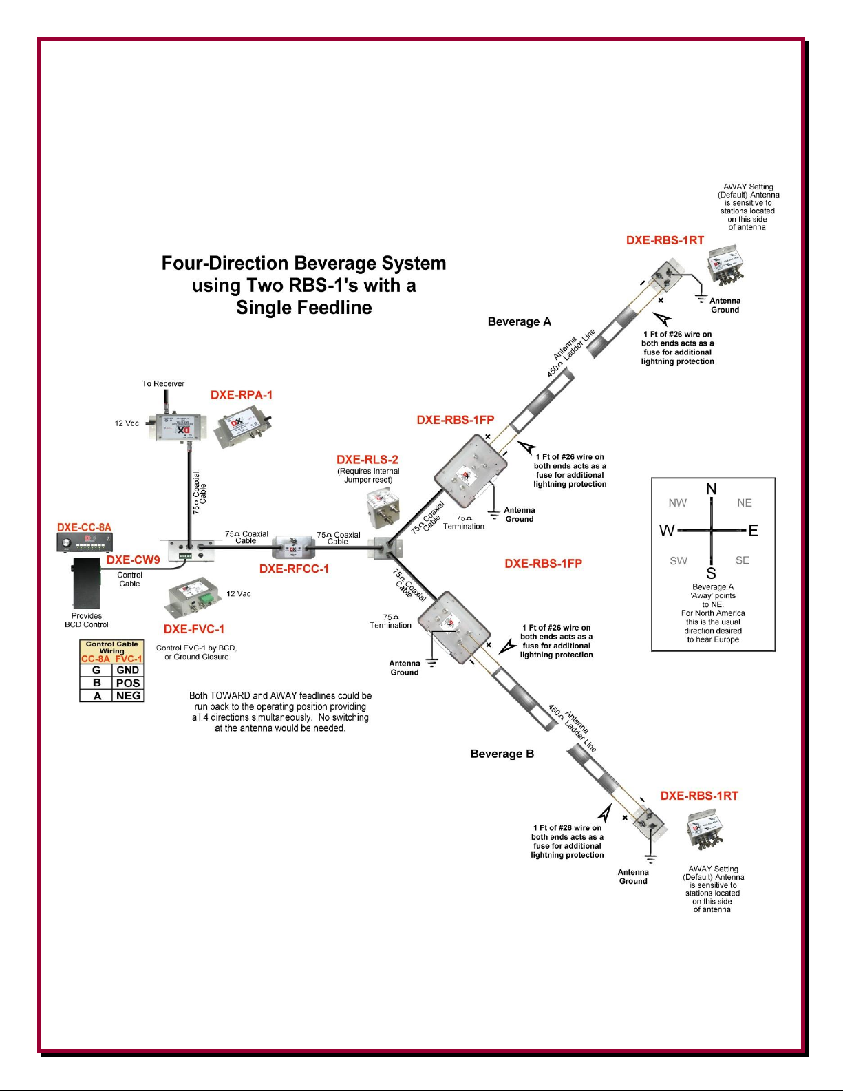
Figure 6 shows a DXE-FVC-1 Feedline Voltage Coupler used to supply controlling voltages for a
Four-Direction Beverage System using two DXE-RBSA-1P Reversible Beverage Systems, along
with a DX Engineering DXE-RLS-2, 2-port receiving antenna switch, to build a four direction
Beverage system using a single feedline. One or more DXE-RLS-2’s can be used to expand larger
Beverage arrays and share the feedline back to the operating position.
Figure 6 - Four-Direction Beverage System
11
Page 12

Figure 7 has the DXE-FVC-1 Feedline Voltage Coupler used for controlling a DXE-RFS-TS2P
Complete Receive Four Square Array Package.
Figure 7
12
Page 13

Figure 8 uses a DXE-FVC-1 Feedline Voltage Coupler to supply the switching voltages for a
Voltage Applied
only to Feedline
not to Ports
Selected Port
0 Vdc
Port A
+12 Vdc
Port B
-12 Vdc
Port C
12 Vac
Port D
system that has four different receive ports using three DXE-RLS-2 Two Port Receive Antenna
Switches, one modified internally (refer to the DXE-RLS-2 manual).
This four position switching system may be used for four antennas or four radio receivers.
Figure 8 - DXE-RLS-2 Configured to Switch 4 Ports
13
Page 14

Figure 9 has the DXE-FVC-1 Feedline Voltage Coupler providing the control voltages for a
Single Transmit Antenna System using a DXE-RBS-1 Reversible Beverage Antenna System with
the DXE-RTR-1 Receive Antenna Interface for transceivers which lack a receive antenna input.
Figure 9
14
Page 15

Figure 10 uses the
DXE-FVC-1 Feedline
Voltage Coupler to control
two Single Direction
Beverage Antenna Systems.
Figure 10
15
Page 16

Figure 11 uses the DXE-FVC-1
Feedline Voltage Coupler to control
a Two Element Dual Direction Offset
Beverage Phased Array.
Figure 11
16
Page 17

Optional Items
DXE-RFS-TS2P - Complete Receive Four Square Array Package for Close Spacing to Transmit Antennas
Complete Receive Four Square Array package for Close Spacing to Transmit Antenna
W8JI design
Operates from 100 kHz to 30 MHz
Excellent directivity in a small space for better signal-to noise ratio
Switchable in four 90 degree spaced directions
Reduced susceptibility to high angle signals compared to EWE, Flag, Pennant, or K9AY arrays
Complete Receive Four Square Array Package for Close spacing to transmit antenna includes:
(1) DXE-ARAV2-4P Package of 4 Active Receive Vertical Antennas w/ Internal Antenna Disconnect Relays
(1) DXE-RFS-2 Receiving Four Square Antenna Switch
(1) DXE-CC-8A 8 Position Control Console
(1) DXE-TVSU-1 Time Variable Sequence Unit
(1) DXE-F6-1000 CATV F-6 Style Coax, 75-ohm, F6 Flooded for Direct Burial, 1000' Spool
(25) DXE-SNS6-25 Snap-N-Seal 75-ohm Coax Connectors for CATV F-6 Cable
(1) DXE-SNS-CT1 Crimp Tool for Snap-N-Seal 75-ohm Coax Connectors
(1) DXE-CPT-659 CATV F-6, RG-6 and RG-59 Coax Cable Stripper, Includes 1 Replacement Blade
DXE-CC-8A Control Console, 8 Position
The CC-8A Control Console is a flexible, 8-position controller used to control the DX Engineering RR8 series antenna switches, the
RFS-2P Receive Four Square controller or any product that uses a 12 or 24* Vdc 1-of-8 or BCD control format. The attractive metal
housing is powder-coated and features an ON/OFF switch, ergonomic selector knob and eight front-panel LED's, with adjustable
brightness, to indicate switch position.
The rear panel external plug allows the control cable to be easily unplugged during weather events or if the shack needs to be
rearranged. We suggest unplugging the CC-8A control leads when severe weather is expected. The use of a lightning protector on the
control lines, such as the PolyPhaser PPC-IS-RCT, available from DX Engineering, is prudent as well.
Shielded CAT-5 type cable can be used for the control cable. (8 conductors plus ground). DXE-CW9S is a top quality 9-conductor
stranded, shielded cable for best results.
For most applications requiring 12 vdc switching, your existing transceiver power supply or the accessory DXE-PSW-12D1A can be
used.
Features
Switching positions: 8
Input voltage: 12/24 Vdc, user supplied
Output voltage: 12/24 Vdc * Dependent on user-supplied dc input power source.
Protection: Dual internal automatic reset fuses
Output format: 3-bit BCD or standard 1-of-8
Dimensions: 8 x 5 x 2.75'' (203.2 x 127 x 69.85 mm) (WxDxH)
DXE-RLS-2 - Two Port Receive Antenna Switch
The DX Engineering 2-Port Receiving Antenna Switch RLS-2 is designed to allow selection of one of two output ports (generally
connected to different receiving antennas) from one feedline. Transfer activates with application of a +10-15 Vdc or 9-12 Vac control
voltage through the feedline.
Features
Metal housing for superior shielding and long life
High quality components
Reliable F-type connectors
Operating range from 300 kHz to 30 MHz with 75 Ω systems
Jumper-selectable, control voltage pass-thru to the selected port
When used with two DX Engineering RBS-1 Reversible Beverage Systems, the RLS-2 will allow selection of four directions using a
single main feedline. Install one or more RLS-2’s to expand larger Beverage arrays and share the feedline back to the operating
position. The DX Engineering FVC-1 Voltage Coupler can be used to supply the control voltages through the feedline to control 4direction switching of an receiving array (using two RLS-2's) or selection of four different receiving antennas.
17
Page 18

DXE-CW9S - Shielded Control Wire, 9 conductor stranded, per foot
DXE-CW9S is a high quality shielded outdoor cable. It features 9 #24 AWG stranded conductors with
aluminum foil shielding plus a #24 stranded tinned copper drain wire. This gives you 8 switch positions plus
common ground - plus the separate shield. It has a gray PVC jacket. This cable is ideal for DX Engineering
Remote Antenna Switches and Four Square arrays, and should be considered for any low-current custom
remote switching application you have - such as receiving antenna arrays. Order by the foot in the length you
require. Price shown is per foot. A nice feature is the "rip cord", which allows for easy stripping of the heavy
jacket without worry about nicking or accidentally cutting the conductors.
COMTEK Control Wire, 3 Conductor, Sold per Foot - COM-CW3
A high quality, PVC jacketed 3-wire control cable, COM-CW3 consists of 3 #20 AWG conductors. It may be used in a
multitude of control cable applications, such as remote switching and antenna rotators.
Sold by the foot - order the length you need.
COMTEK Control Wire, 4 Conductor, Sold per Foot - COM-CW4
A high quality, PVC jacketed 4-wire control cable, COM-CW4 consists of 4 #20 AWG conductors. It may be used in a
mulititude of control cable applications, such as remote switching and antenna rotators.
Sold by the foot - order the length you need.
DXE-F6-1000 - 75-ohm F-6 Style Direct Bury Coax, 1000 ft. Spool Hi Quality, 75-ohm F6 type "Flooded" Coax Sold by
the spool, or as Custom Cable Assemblies
Center Conductor: 18 AWG Copper-Clad Steel , Nominal Diameter: 0.040 in.
Dielectric: Gas Expanded Polyethylene, Nominal Diameter Over Dielectric: 0.180 in.
Shield: 1st Shield: Aluminum-Polypropylene-Aluminum, Laminated Tape with overlap Bonded to the Dielectric,
Nominal Diameter Over Tape: 0.187 in. 2nd Shield: 34 AWG Aluminum Braid Wire, 60% Coverage
Jacket: PE (Flooded for Underground), Nominal Diameter Over Jacket: 0.272 in. , Nominal Jacket Thickness: 0.030 in.
Electrical Properties: Impedance: 75.0 +/- 3.0-ohms, Velocity of Propagation: 85.0% Nominal
We recommend the use of Snap-N-Seal connectors to ensure a high quality and weather resistant feedline connection. The
proper tool must be used to install these connectors.
DXE-CPT-659 - oax Cable Stripper for CATV F-6, RG-6 and RG-59 coax
Prepares CATV F-6, RG-6 and RG-59 coax cable for the installation of an "F" type connector.
One-step cutting motion
Precision cut
No nicks or scratches to conductor
Includes 1 replacement blade
DXE-RTV598335 - Permatex Black RTV Sealant, Non-Acetic - 3.3 oz Tube, Black
DX Engineering Approved RTV Sealant - We have all used RTV to seal water out of things, right? Have you ever sealed a piece of
electronic gear with it -- then opened it some time later to find that it had still managed to become corroded inside?
Guess what? It's not the rain that corroded it - It's the RTV! Normal RTV gives off acetic acid when it cures. That's
the vinegar smell. The acetic acid causes the corrosion.
DX Engineering has located a Neutral Cure RTV made right here in Ohio that is non-corrosive and is safe for sealing
those baluns and other electronic gear that are going to be out in the weather.
Applies just like "normal" RTV, dries in one hour and cures in 24 hours at 70 degrees F.
And it doesn't smell like vinegar!
3.3 oz. Tube - Black
*This part is classified hazardous and is limited to domestic UPS Ground shipping only
18
Page 19
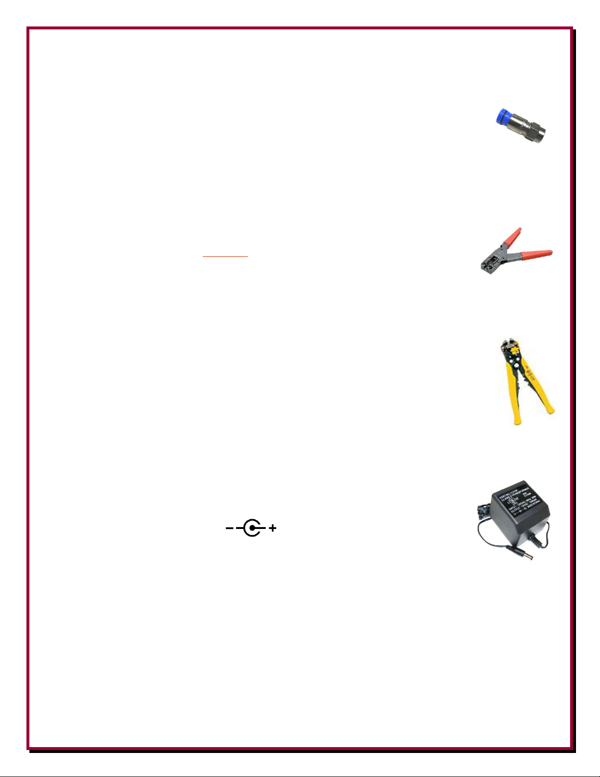
DXE-SNS6-25 - Watertight Coax Connector, Snap-N-Seal for CATV F-6 Cable, 25 pieces
Snap-N-Seal is an environmentally sealed CATV F coax connector system for harsh environments. The connectors have a unique,
360 degree radial compression system that offers the signal leakage protection required for high performance receive systems.
Quad sealed system prevents moisture from migrating into the connection
360 degree radial compression provides superior RF integrity (-95dB typical, 60% bonded foil cable)
Easy cable preparation
Connector to cable retention of 40 lbs minimum
Superb impedance match to 1 GHz
Manufactured of high quality 360 brass, cadmium plated with yellow chromate coating for maximum corrosion resistance
UV-resistant plastic and O-rings provide a reliable environmentally sealed connector
An installation tool, such as the DXE-SNS-CT1, is required to install the connectors. Normal crimping tools or pliers will not work.
DXE-SNS-CT1 - Compression Tool for Snap-N-Seal 75-ohm Coax Connectors
Ratchet compression tool for installing Snap-N-Seal 75-ohm Coax connectors. Ordinary pliers will not install these
connectors properly.
DXE-900031 - Automatic Wire Stripper/Crimper/Cutter, 24-10 Ga.
Our DX Engineering wire stripper uses a spring-loaded design to make quick work of wires ranging from 24 to 10
gauge. Just insert the wire, squeeze the handle, and listen for the click. That’s the sound of another perfect wire
stripping job performed in about 2 seconds- a fraction of the time it takes your pocket knife to do the same job.
An adjustable wire length guide helps you make uniform strips, and a built-in wire cutter and crimper helps you
complete your wiring job.
Spring-loaded design - Strips wires ranging from 24 to 10 gauge - built-in wire cutter and crimper
DXE-PSW-12D1A - AC Adapter 12 Volt DC 1000 mA Wall Transformer
120 Vac 60 Hz input - 12 Vdc, 1 Amp, Fused output. A standard 2.1 mm plug connection for 12 Vdc.
Outer connection is GROUND Center Pin is input for +12 VDC.
19
Page 20

Technical Support
If you have questions about this product, or if you experience difficulties during the installation,
contact DX Engineering at (330) 572-3200. You can also e-mail us at:
DXEngineering@DXEngineering.com
For best service, please take a few minutes to review this manual before you call.
Warranty
All products manufactured by DX Engineering are warranted to be free from defects in material and workmanship for a
period of one (1) year from date of shipment. DX Engineering’s sole obligation under these warranties shall be to issue
credit, repair or replace any item or part thereof which is proved to be other than as warranted; no allowance shall be
made for any labor charges of Buyer for replacement of parts, adjustment or repairs, or any other work, unless such
charges are authorized in advance by DX Engineering. If DX Engineering’s products are claimed to be defective in
material or workmanship, DX Engineering shall, upon prompt notice thereof, issue shipping instructions for return to
DX Engineering (transportation-charges prepaid by Buyer). Every such claim for breach of these warranties shall be
deemed to be waived by Buyer unless made in writing. The above warranties shall not extend to any products or parts
thereof which have been subjected to any misuse or neglect, damaged by accident, rendered defective by reason of
improper installation, damaged from severe weather including floods, or abnormal environmental conditions such as
prolonged exposure to corrosives or power surges, or by the performance of repairs or alterations outside of our plant,
and shall not apply to any goods or parts thereof furnished by Buyer or acquired from others at Buyer’s specifications.
In addition, DX Engineering’s warranties do not extend to other equipment and parts manufactured by others except to
the extent of the original manufacturer’s warranty to DX Engineering. The obligations under the foregoing warranties
are limited to the precise terms thereof. These warranties provide exclusive remedies, expressly in lieu of all other
remedies including claims for special or consequential damages. SELLER NEITHER MAKES NOR ASSUMES ANY
OTHER WARRANTY WHATSOEVER, WHETHER EXPRESS, STATUTORY, OR IMPLIED, INCLUDING
WARRANTIES OF MERCHANTABILITY AND FITNESS, AND NO PERSON IS AUTHORIZED TO ASSUME
FOR DX ENGINEERING ANY OBLIGATION OR LIABILITY NOT STRICTLY IN ACCORDANCE WITH THE
FOREGOING.
©DX Engineering 2017
DX Engineering®, DXE®, DX Engineering, Inc.®, Hot Rodz®, Maxi-Core®, DX Engineering THUNDERBOLT®, DX
Engineering Yagi Mechanical®, EZ-BUILD®, TELREX®, Gorilla Grip® Stainless Steel Boom Clamps, Butternut®,
SkyHawk™, SkyLark™, SecureMount™, OMNI-TILT™, RF-PRO-1B®, AFHD-4® are trademarks of PDS Electronics,
Inc. No license to use or reproduce any of these trademarks or other trademarks is given or implied. All other brands
and product names are the trademarks of their respective owners.
Specifications subject to change without notice.
20
 Loading...