

Page 1

CC-8A Control Console
DXE-CC-8A
DXE-CC-8A-INS Revision 1c
© DX Engineering 2017
1200 Southeast Ave. - Tallmadge, OH 44278 USA
Phone: (800) 777-0703 ∙ Tech Support and International: (330) 572-3200
Fax: (330) 572-3279 ∙ E-mail: DXEngineering@DXEngineering.com
Page 2
Table of Contents
Introduction
2
Specifications
2
Theory of Operation
3
Installation
3
Front Panel
3
Rear Panel
4
Relay (1 of 8) and BCD Output Voltage
6
Maintenance
7
Lightning Protection
7
Technical Support
8
Warranty
8
Switching Positions
Eight
Power Required
+ 12 Vdc (nominal) 1 to 1.5 A
Output Control Voltage
+ 12 Vdc (nominal)
LED (Light Emitting Diode) Brightness
Fully Adjustable
DC Output Protection
Internal automatic reset fuse
Output format
Standard 1-of-8 and BCD
Introduction
Congratulations on your purchase of the CC-8A Control Console. Its unique design features both 1of-8 and BCD control. This allows it to be used with existing 1-of-8 systems like the DX
Engineering DXE-RR8-HP remote 8 port RF switch, or BCD systems like the DXE-RFS-2P and
DXE-FVC-1. Its universal nature allows operation with any 1-of-8 or BCD system of compatible
voltage. We know you are anxious to get started but before you install the CC-8A, take a few
minutes to read this brief user guide and familiarize yourself with the installation, operation and
safety procedures. We are confident that you will find this control console easy to use and that it
will reward you with years of faithful service.
This unit is RoHS (Reduction of Hazardous Substances) compliant. The components, including the
solder used are all lead free. If you decide to do any modifications or internal repairs, you
should use only lead free solder and lead free soldering tools. Lead free solder melts
approximately 100 degrees (F) higher than the old leaded solder, so you may need to
upgrade your current soldering system.
Specifications
2
Page 3

Theory of Operation
The DXE-CC-8A has two easy to use rear panel connector plugs and sockets for control line
connections plus one connection for +12 Vdc. The two green plugs are easy to wire. Connections
are made with a screwdriver; no soldering is required. Not only does this make the CC-8A easy to
install, it also allows easy quick disconnect during periods of extended non-use for lightning
protection or if the CC-8A is relocated to another area of your operating position. The brightness
adjustment for the front antenna switch LED (Light Emitting Diode) indicators is also located on
the rear panel. The CC-8A has an attractive wear resistant laminated front panel to maintain
appearance even with constant use.
Installation
The CC-8A is designed for indoor use only. Mount the CC-8A at any convenient location but avoid
condensation, exposure to heat from amplifiers or other high power equipment. Constant exposure
to temperatures above 150 degrees F (65C) will shorten the life of the CC-8A, and should be
avoided.
Front Panel
Eight Position Knob Eight Green LEDs Power On/Off Toggle Switch
Figure 1 - Front Panel
3
Page 4

Rear Panel
DC Input LED Brightness Knob J1 - 1 of 8 Connector J2 - BCD Connector
Figure 2 - Rear Panel
The CC-8A has two removable plug and socket connectors for control line connections on the rear
panel. Connections are made with a screwdriver; no soldering is required. Do not attempt to solder
wires to the connector, and do not over-tighten the screws. Remove 1/4 inch of insulation from each
control wire so the screw terminals tighten on the wire and not the insulation. This will also protect
adjacent wires from the potential of shorting together. Stranded wire should be tightly twisted or
very lightly tinned before insertion. Open terminal slots by turning the screws CCW before wire
ends are inserted. Do not force the screw beyond the stop.
Figure 3 - CC-8A Rear Connectors
The green connector plugs/sockets on the rear of the DXE-CC-8A are in two parts. The top
connector part can be removed by pulling it straight off. This will allow easier wire replacement or
servicing as needed. When pushing the connector top back in place, ensure you press straight
inward.
A Cable P-Clamp is provided to run the control cable through for strain relief. A 9-wire (including
ground) control cable with minimum 24 AWG size conductors should provide satisfactory results
for runs to approximately 1000 feet when used with the DX Engineering DXE-RR8-HP series
switches or 500 feet when used with the DXE-RR8-SD switch (use 1 of 8 type connections). A
good quality, shielded CAT5 cable such as DXE-CW9 Shielded Control Wire can be used provided
4
Page 5
the shield ground wire is used for the GND connection. The feedline shield can also be used for the
Minimum Copper Wire
Gage (AWG)
Length
24
1,000 feet
22
1,500 feet
20
2,000 feet
ground path if the shield is attached to the GND on the CC-8A and to the station ground.
Note: The total loop resistance of the control cable path must be under 30 ohms for
reliable operation.
The brightness for the front panel indicator LED’s is fully adjustable by the potentiometer on the
rear panel. Select the relay control voltage before adjusting LED Brightness.
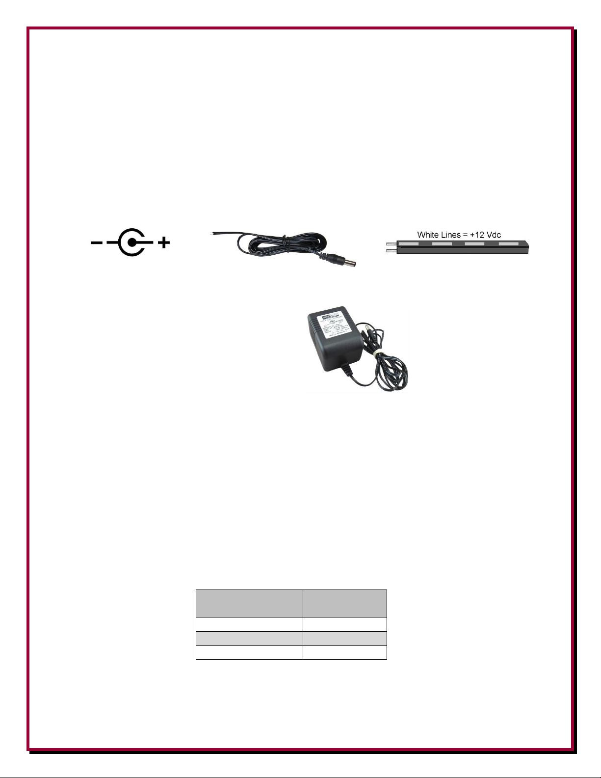
The DC Input requires 12 Vdc (nominal). One 2.1 mm power cable is included.
An optional wall transformer is available from DX Engineering that supplies 12 Vdc @ 1 amp.
Optional DXE-PSW-12D1A
AC Adapter +12 Volt DC, 1000 mA
Wall Transformer
Control lines can normally use good quality CAT5e cable (4 twisted pairs of 24 AWG wire) for
runs up to 1000 feet. Typical DX Engineering BCD control lines requirements are +12 VDC at 25
milliamps.
Depending on the number of control lines needed (usually 3 or 4) you can double up the twisted
pairs of CAT5e cable, or use control wire that is at least 22 AWG, allowing runs up to 1500 feet. If
you use a cable with more conductors, it is a good idea to tie the unused conductors to ground.
For longer runs of control cable, use a line loss calculator to ensure you supply the proper control
levels needed.
Approximate BCD Control Line Lengths (can use this also for 1 of 8 control wires).
5
Page 6

BCD and 1 of 8 Output Voltages
LED ON
G A B C G
1
GND 0 0 0 GND
2
GND 1 0 0 GND
3
GND
0 1 0
GND
4
GND
1
1
0
GND
5
GND 0 0 1 GND
6
GND 1 0 1 GND
7
GND
0
1
1
GND
8
GND
1 1 1
GND
LED
ON
G 1 2 3 4 5 6 7 8
G
1
GND
1
0 0 0 0 0 0 0
GND
2
GND
0 1 0 0 0 0 0 0 GND
3
GND
0
0 1 0 0 0 0 0
GND
4
GND
0 0 0 1 0 0 0 0 GND
5
GND
0 0 0
0 1 0 0 0
GND
6
GND
0 0 0 0 0 1 0 0 GND
7
GND
0 0 0 0 0
0 1 0
GND
8
GND
0 0 0 0 0 0 0 1 GND
The CC-8A supplies a 12 Vdc BCD or 1-of-8 control voltage to external devices.
The DX Engineering RR8 remote 8-port RF switch requires a nominal 12 Vdc relay control
voltage. If you are using another switch, ensure the proper control voltage is selected before you
power-on the Control Console.
The relay control voltage in BCD format is present on the 5 terminal, BCD connector corresponding
to the front panel LED indicators as depicted in Table 1. The “1” signifies the output voltage
present between that terminal and either pin G (Ground).
Table 1 - BCD Output Truth Table
The brightness for the front panel indicator LED’s is fully adjustable by the potentiometer on the
rear panel.
The relay control voltage in 1-of-8 format is present on the 10 terminal, 1-of-8 connector,
corresponding to the front panel LED indicator as depicted in Table 2. The “1” signifies the output
voltage present between that terminal and either pin G (Ground).
Table 2 - 1-of-8 Output Truth Table
6
Page 7

Maintenance
The CC-8A requires virtually no maintenance as long as the unit is not exposed to direct sunlight,
moisture, voltage or current overloads, or extreme temperatures.
The CC-8A has high-friction rubber feet. These feet are soft, and should not be exposed to
petroleum based cleaners or solvents. They can, on occasion, leave a black mark on a cabinet or
desk like any soft rubber might do. Avoid stacking this unit on any cabinets where appearance is a
major concern.
A thermal, automatically-resetting fuse also protects the CC-8A and is located internally on the dc
output leads. The DC output fuse usually never needs to be replaced since the internal thermal fuse
resets in just a few seconds.
Clean the CC-8A with Windex® or other mild cleaners suitable for use on plastics. Avoid petroleum
products.
Lightning Protection
As with any electrical device, lightning is a concern. The robust construction and sturdy parts used
in the CC-8A offers a great deal of lightning and surge protection. The best protection is to
disconnect electrical devices during storms, and we have taken the unique step of providing
connectors on the rear of the CC-8A that unplug. We suggest unplugging the CC-8A control leads
when severe weather is expected. The use of a lightning protector, such as the DXE-IS-RCT - DC
Shunt Control Line Protector, available from DX Engineering, is prudent as well.
Proper grounding of feedlines and equipment and maintaining integrity of shield connections is
paramount to avoiding severe lightning damage. Consult lightning protection and station grounding
information in the ARRL handbooks, NAB Broadcast Handbook or other reliable sources. Always
remember good grounds and proper feedline connections improve lightning protection and
transmitting and receiving performance.
7
Page 8

DXE-IS-RCT DC Shunt Control Line Protector
DX Engineering Rotator Control Line Protector is a custom made surge protector designed for use on rotator cables - up to 8
conductors. Also ideal for control lines of remote antenna switches and any low voltage control system where voltages are normally
below 60 Vdc or ac.
DXE-IS-RCT features include:
* Weatherproof metal enclosure with cover, mounting stud and terminal gaskets to deter water from
entering the enclosure.
* Terminal strips to connect up to eight rotator control wires
* 1/4 in. x 20 mounting stud allowing multiple mounting configurations
* Each line connection has an individual shunt MOV for maximum surge protection
* Voltage spikes exceeding 82 Vdc (in either polarity) will be shunted to ground
* RoHS compliant construction
DXE-CW9S - Shielded Control Wire, 9 conductor stranded, per foot
DXE-CW9S is a high quality shielded outdoor cable. It features 9 #24 AWG stranded conductors with aluminum
foil shielding plus a #24 stranded tinned copper drain wire. This gives you 8 switch positions plus common ground plus the separate shield. It has a gray PVC jacket. This cable is ideal for DX Engineering Remote Antenna Switches
and Four Square arrays, and should be considered for any low-current custom remote switching application you have
- such as receiving antenna arrays. Order by the foot in the length you require. Price shown is per foot.
A nice feature is the "rip cord", which allows for easy stripping of the heavy jacket without worry about nicking or accidentally
cutting the conductors.
DXE-CW9-1K - Shielded Control Wire, 9 conductor, 1000 ft reel
DXE-CW9 - Shielded Control Wire, 9 conductor, per foot
DXE-CW9-1K is a 1000 foot box of high quality shielded outdoor FTP (Foil Twisted Pair) Cat5e cable. It features 4
Twisted pairs of 24 AWG solid wire with Al foil shielding plus a solid tinned copper drain wire - providing a total of 9
conductors for DC switching applications. It has a polyethylene jacket and is rated for direct burial. This cable is ideal for DX
Engineering Remote Antenna Switches and Four Square arrays, and should be considered for any low-current custom remote
switching application you have - such as receiving antenna arrays. A nice feature is the "rip cord", which allows for easy
stripping of the heavy jacket without worry about nicking or accidentally cutting the conductors. Excellent for use in all
outdoor applications of switching, networking, data transfer and phone lines. As a data transfer line, it supports
10/100/1000Mbps.
DXE-PSW-12D1A - AC Adapter 12 Volt DC 1000 mA Wall Transformer
120 Vac 60 Hz input - 12 Vdc, 1 Amp, Fused output. A standard 2.1 mm plug connection for 12 Vdc.
Outer connection is GROUND Center Pin is input for +12 VDC.
Technical Support
If you have questions about this product, or if you experience difficulties during the installation, contact DX Engineering at (330)
572-3200. You can also e-mail us at:
DXEngineering@DXEngineering.com
For best service, please take a few minutes to review this manual before you call.
This unit is RoHS (Reduction of Hazardous Substances) compliant. The components, including the solder used are all lead free. If you decide
to do any modifications or internal repairs, you should use only lead free solder and lead free soldering tools. Lead free solder melts
approximately 100 degrees (F) higher than the old leaded solder, so you may need to upgrade your current soldering system.
Warranty
All products manufactured by DX Engineering are warranted to be free from defects in material and workmanship for a period of one (1) year from date of shipment. DX Engineering’s sole obligation
under these warranties shall be to issue credit, repair or replace any item or part thereof which is proved to be other than as warranted; no allowance shall be made for any labor charges of Buyer for
replacement of parts, adjustment or repairs, or any other work, unless such charges are authorized in advance by DX Engineering. If DX Engineering’s products are cl aimed to be defective in material
or workmanship, DX Engineering shall, upon prompt notice thereof, issue shipping instructions for return to DX Engineering (transportation-charges prepaid by Buyer). Every such claim for breach of
these warranties shall be deemed to be waived by Buyer unless made in writing. The above warranties shall not extend to any products or parts thereof which have been subjected to any misuse or
neglect, damaged by accident, rendered defective by reason of improper installation, damaged from severe weather including floods, or abnormal environmental conditions such as prolonged exposure
to corrosives or power surges, or by the performance of repairs or alterations outside of our plant, and shall not apply to any goods or parts thereof furnished by Buyer or acquired from others at
Buyer’s specifications. In addition, DX Engineering’s warranties do not extend to other equipment and parts manufactured by others except to the extent of the original manufacturer’s warranty to DX
Engineering. The obligations under the foregoing warranties are limited to the precise terms thereof. These warranties provide exclusive remedies, expressly in lieu of all other remedies including
claims for special or consequential damages. SELLER NEITHER MAKES NOR ASSUMES ANY OTHER WARRANTY WHATSOEVER, WHETHER EXPRESS, STATUTORY, OR IMPLIED,
INCLUDING WARRANTIES OF MERCHANTABILITY AND FITNESS, AND NO PERSON IS AUTHORIZED TO ASSUME FOR DX ENGINEERING ANY OBLIGATION OR LIABILITY
NOT STRICTLY IN ACCORDANCE WITH THE FOREGOING.
©DX Engineering 2017
DX Engineering®, DXE®, DX Engineering, Inc.®, Hot Rodz®, Maxi-Core®, DX Engineering THUNDERBOLT®, DX Engineering Yagi Mechanical®, EZ-BUILD®, TELREX®, Gorilla Grip® Stainless
Steel Boom Clamps, Butternut®, SkyHawk™, SkyLark™, SecureMount™, OMNI-TILT™, RF-PRO-1B®, AFHD-4® are trademarks of PDS Electronics, Inc. No license to use or reproduce any of
these trademarks or other trademarks is given or implied. All other brands and product names are the trademarks of their respective owners.
Specifications subject to change without notice.
8
 Loading...