

Page 1

65 Foot Telescoping
Aluminum Antenna Tubing Kit
with Guy Rings
DXE-ATK65A
DXE-ATK65A-INS-Rev 1a
© DX Engineering 2018
1200 Southeast Ave. - Tallmadge, OH 44278 USA
Phone: (800) 777-0703 ∙ Tech Support and International: (330) 572-3200
Fax: (330) 572-3279 ∙ E-mail: DXEngineering@DXEngineering.com
- 1 -
Page 2

Introduction
Quantity
DX Engineering
Part Number
Size
Wall
Thickness
Slit
Element
Length
1
DXE-AT1244
0.875"
7/8"
.058"
One End
36"
1
DXE-AT1209
1.000"
1"
.058"
One End
72"
1
DXE-AT1210
1.125"
1-1/8"
.058"
One End
72"
1
DXE-AT1211
1.250"
1-1/4"
.058"
One End
72"
1
DXE-AT1212
1.375"
1-3/8"
.058"
One End
72"
1
DXE-AT1213
1.500"
1-1/2"
.058"
One End
72"
1
DXE-AT1214
1.625"
1-5/8"
.058"
One End
72"
1
DXE-AT1215
1.750"
1-3/4"
.058"
One End
72"
1
DXE-AT1216
1.875"
1-7/8"
.058"
One End
72"
1
DXE-AT1217
2.000"
2"
.058"
One End
72"
1
DXE-AT1222
2.125"
2-1/8"
.058"
Both Ends
72"
1
DXE-AT1313
2.000"
2"
.120"
none
72"
2
DXE-ECL-2250
Stainless Steel Clamp for 2.125” and 2.25" with Straight Slot or 5/16” Drive Nut
2
DXE-ECL-2000
Stainless Steel Clamp for 1.875” and 2" with Straight Slot or 5/16” Drive Nut
2
DXE-ECL-1750
Stainless Steel Clamp for 1.625” and 1.75" with Straight Slot or 5/16” Drive Nut
2
DXE-ECL-1500
Stainless Steel Clamp for 1.375” and 1.5" with Straight Slot or 5/16” Drive Nut
2
DXE-ECL-1250
Stainless Steel Clamp for 1.125” and 1.25" with Straight Slot or 5/16” Drive Nut
1
DXE-ECL-1000
Stainless Steel Clamp for 1" with Straight Slot or 5/16” Drive Nut
1
DXE-GR-5P
DX Engineering Guy Ring, set of 5: 2”, 1-1/2”, 1-1/4”, 1” and 3/4”
The DXE-ATK65A Aluminum Antenna Tubing Kit is constructed of twelve pieces of high quality
aluminum tubing with eleven Stainless Steel clamps and one set of DX Engineering DXE-GR-5P Guy
Rings. When fully assembled, the overall length is 65 feet. Depending on your application, the length can
easily be made shorter by telescoping the elements inward, or removing element sections.
The Aluminum Antenna Tubing Kit is used to make various vertical antennas, or the basics for heavy duty
dipoles. Amateur Radio Operators love to experiment and this antenna element stack is an ideal starting
point. The telescoping aluminum tubing sizes allow adjustment by the addition or removal of tubing
sections as length requirements dictate. Smaller diameter sizes are available from DX Engineering to make
a longer assembly. The Aluminum Antenna Tubing Kit is not designed to support other antennas, nor
should it be treated as if it were a tower support.
DX Engineering Type 6063-T832 drawn - not extruded - aluminum tubing in three foot and six foot
lengths with four slits at one end for fast reliable assembly. In this kit, the 2.125" OD tubing section has
slits at both ends and the 2" OD heavy wall (.120") section has no slits.
Rugged aluminum alloy 6063 is most commonly used for seamless structural tube and pipe. It is popular
in structural use for both its high strength and great, long lasting appearance. Alloy 6063 provides great
resistance to general corrosion, including resistance to stress-corrosion cracking.
Eleven of the aluminum tubes in this kit are six feet in length. The top tube in this kit is three feet in length.
Parts Included:
- 2 -
Page 3

WARNING!
INSTALLATION OF ANY ANTENNA NEAR POWER LINES IS DANGEROUS
Warning: Do not locate any of the aluminum tubing near overhead power lines or other electric
light or power circuits, or where it can come into contact with such circuits. When installing any
antenna or aluminum tubing, take extreme care not to come into contact with such circuits, because
they may cause serious injury or death.
Overhead Power Line Safety
Before you begin working, check carefully for overhead power lines in the area you will be
working. Don't assume that wires are telephone or cable lines: check with your electric utility for
advice. Although overhead power lines may appear to be insulated, often these coverings are
intended only to protect metal wires from weather conditions and may not protect you from electric
shock
Keep your distance! Remember the 10-foot rule: When carrying and using ladders and other long
tools, keep them at least 10 feet away from all overhead lines - including any lines from the power
pole to your home.
Guy Rings
The included DXE-GR-5P - DX Engineering Guy Rings advance the art of
stabilizing vertical rigid telescopic tubing. These engineered and incredibly
strong Guy Rings are intended for rope guying DX Engineering, Hustler, and all
brands of aluminum tubing vertical antennas, as well as the DX Engineering
Telescoping Fiberglass and Aluminum Tubing Kits. DX Engineering Guy Rings
are made from the super strong, black UV resistant, glass-reinforced poly-resin
material. They are virtually impervious to extreme outdoor conditions and mechanical stress. With
their 1/2 in. thick center hole shoulder, these Guy Rings simply slide over their respective tubing
size and seat firmly against the top of the larger tubing section below. 5 Rings per set: Fits tubing
sizes 2”, 1-1/5”, 1-1/4”, 1” and 3/4”. The 3/4” Guy Ring will not be used with the DXE-ATK65A.
Assembly
For a full 65 foot length, the aluminum tubing sections are assembled starting at the bottom 2" OD,
heavy wall (.120") aluminum tube and working upward.
Note: Jet-Lube SS-30 (JTL-12555) should be used between all antenna element sections. Jet
Lube SS-30 is an electrical joint compound to affect a substantial electrical connection
between metal parts such as telescoping aluminum tubing or other antenna pieces. It
ensures high conductivity at all voltage levels by displacing moisture and preventing
corrosion or oxidation. Jet-Lube should also be used on all clamps, bolts and stainless
steel threaded hardware to prevent galling and to ensure proper tightening.
- 3 -
Page 4

When assembling any telescoping aluminum tubing sections you should take the following steps:
Caution
Aluminum tubing edges can be very sharp.
Take precautions to ensure you do not get accidentally cut.
1. Make sure the edges are smooth and not sharp. Deburring may be necessary, since burrs and
shavings can occur on seams as well as edges. All surfaces need to be completely smooth to
allow easy assembly of tubing sections.
The raised particles and shavings that appear when the aluminum tubing is machined are
referred to as burrs, and the process by which they are removed is known as deburring.
Deburring is a finishing method used in manufacturing. Our aluminum tubing is machine cut on
both ends and machine slit on one end. Although DX Engineering manufactured
aluminum tubing is deburred, you should further assure
that there are no ragged edges or protrusions.
Use the DXE-UT-KIT-DBR Tube Deburring Tools,
DXE-22166 Slim Grip Deburring Tool, or the DXE22600 Deburring Tool with Extending Handle and
Extra Blades for this operation.
2. Clean the inside of the aluminum tubing to clear out any dirt or foreign material that would
cause the aluminum tubing sections to bind during assembly. Do not use any type of oil or
general lubricant between the aluminum tubing sections. Oils or general lubricants can cause
poor electrical connections for radio frequencies.
3. Clean the outside of the aluminum tubing to clear any dirt or foreign material that would cause
the clamps to malfunction during assembly.
4. The use of JTL-12555 Jet-Lube SS-30 is highly recommended as an electrical joint
compound which effects a substantial electrical connection between metal parts such as
telescoping aluminum tubing or other antenna pieces. Using Jet-Lube assures high conductivity
at all voltage levels by displacing moisture and preventing corrosion or oxidation.
5. When assembling the aluminum tubing sections, ensure the area is clear of grass, dirt or other
foreign material that could cause problems during assembly of the closely fitted telescoping
sections.
Assemble the aluminum tubing sections in an area that is flat and has sufficient room for the length
of the assembly. Lay the aluminum tubing out in the order shown in Figure 1. Orient the slits in the
tubes toward the top. The bottom 2" OD section is thick walled and has no slits. The second section
is 2.125" and has slits at both ends. The rest of the tubing sections have 4 slits at one end. The first
11 aluminum sections in this kit are 72" long and the top aluminum section is 36" long.
Each aluminum tubing section is inserted into the next section as shown in Figure 1. Assembly is
easier if the overlaps in the tubing sections are pre-marked. A dark color felt-tip marker works well.
- 4 -
Page 5

Mark each aluminum section as shown in Figure 1 from the end of each aluminum section without
the slit using a marker so it will be clearly visible. If you are clamping the completed aluminum
tubing kit to a mounting plate (example: making a vertical antenna), apply clamps only to this lower
thick walled (.120") section. DXE-SAD-200A 2 inch U-Bolt Saddle Clamps are strongly
recommended for secure clamping without crushing the element tubing.
Figure 1
Locate the hardware pack containing the eleven stainless steel clamps. Also locate the Guy Ring Set
- You can use 4 of the guy rings from the Guy Ring kit with the DXE-ATK65A (3/4” Guy Ring is
not used). Slide the Guy Rings over the tubes along with the clamps
over each aluminum section as shown in Figure 2 before putting the
tubing sections together. You can lightly tighten the clamps just below
the slits in each section to hold them until needed. Align the clamp
screws on each section to face the same direction. At final assembly, the
body of the clamp should be positioned between the slits in the
aluminum tubes and 1/8" from the edge of each aluminum tube as shown
in Figure 2a. Figure 2a
Figure - 2 - Clamp & Guy Rings - Sizes and Locations
Making sure dirt or grass does not adhere to the aluminum tubing to be joined, insert the marked
end of the tube into the next tube allowing for the overlap as shown in Figure 1. Position the
stainless steel clamp. Make sure the body of the clamp is positioned between the slits and tighten
securely. Continue mating aluminum tubes. The guy rings are slipped over the appropriate sized
tubing and will rest on the lip of the tube as shown in the example to the right. Double-check the
tubing sections you have just assembled. Total length should measure 65 feet (780 inches).
- 5 -
Page 6

You may elect to have the tubing in a shorter length. The
aluminum tubing may be telescoped inward, outward, or removed
depending on your application. Keep in mind you want a minimum
of 2 to 8 inches of overlap between tubing sections dependant on
location and overall strength.
Guying and Raising
Some vertical antenna manufacturers indicate their antennas do not
need guying. During times of high winds or ice loading, some of
these verticals may sustain damage or fail altogether. With the
small amount of effort needed to install a four point guying system,
the risk hardly seems worth taking. A three level, four point guying
scheme provides the best mechanical advantage to prevent wind stress, regardless of direction. The
guy lines should be used during raising or lowering to minimize stress on the lower tube sections.
When using an optional DXE-VA-BASE Tilt Base, a three level, four point guying system is
recommended for use when the DX-ATK65A is used as a vertical antenna because just one set of
the guy ropes has to be loosened when you tilt the vertical antenna element downward. The
remaining guys help stabilize the vertical antenna in three directions when being raised by pulling
on the loose guys.
The DXE-GUY1000-KIT has been designed to be used with the DXE-ATK65A or other similar
vertical antennas. The guying kit is ideal for fixed or portable installations.
Figure 3 shows the suggested guying scheme for the DXE-ATK65A assembly when used as a
vertical antenna. Your results may vary since it depends on the length (height) of your particular
installation.
Guying of vertical masts or antennas is always recommended for stability. However, if your area
encounters severe wind velocities or icing conditions, simple additional guying will help prevent the
possibility of failure.
With the DXE-GUY1000-KIT, you can install four sets of guy ropes. Use the suggested no slip
knot placing the loop just above the element clamps shown in Figure 3. Guying should be tightened
just enough to permit the antenna to swing a few inches. The ends of the ropes are tied to the earth
anchors that are screwed into the ground at about the same angle as the ropes will be.
When using the optional DXE-VA-BASE Tilt Base, position the guy ropes as shown in Figure 4.
This will make it easy to raise or lower the vertical antenna and only one set of guy ropes needs to
be loosened. The other guy rope sets will help guide the vertical antenna on the way up by pulling
on the loose guys.
- 6 -
Page 7

Figure 3 - Suggested Guying
- 7 -
Page 8
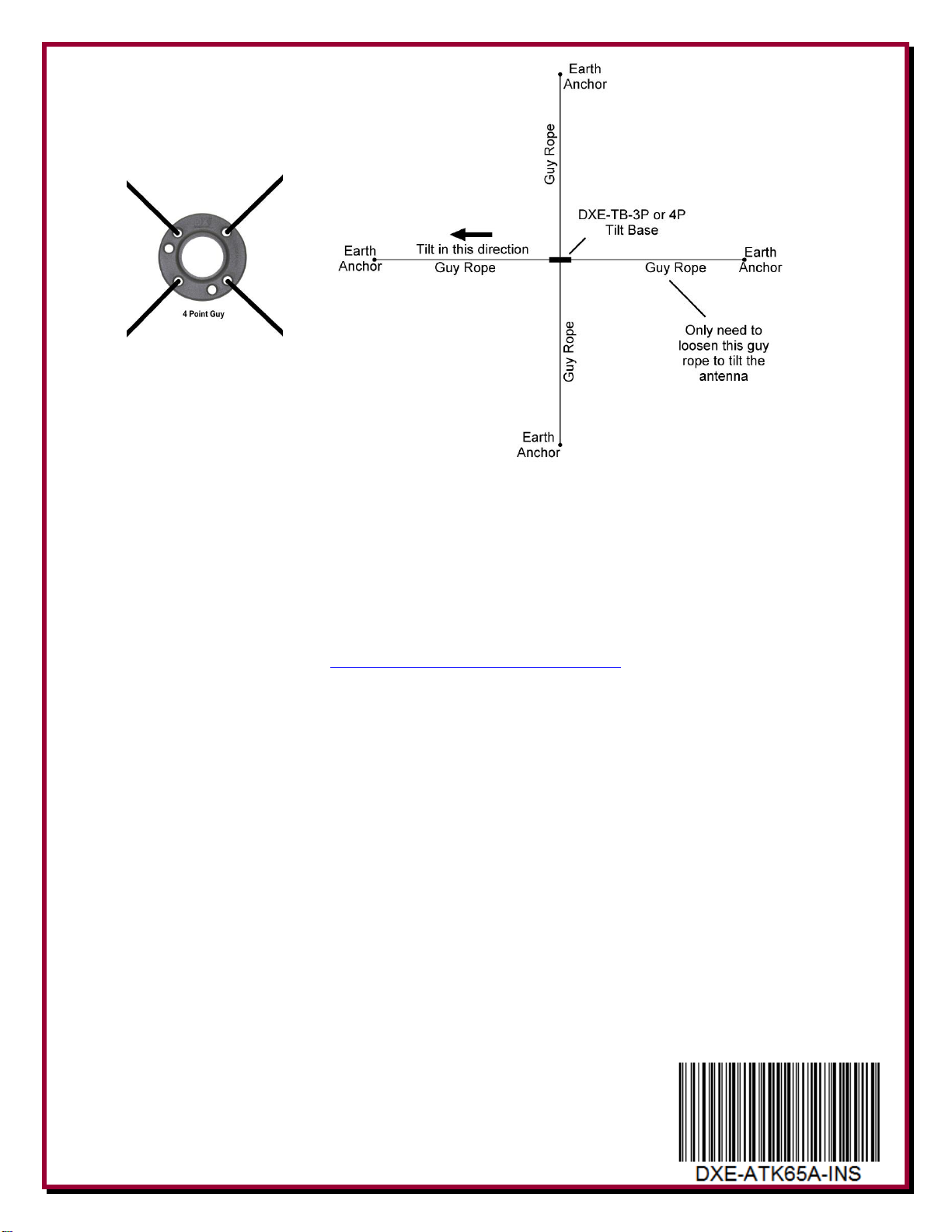
Figure 4 - Four Point Guy Ropes - Overhead View
Depending on your system, additional or varied guying may be required.
Technical Support
If you have questions about this product, or if you experience difficulties during the installation,
contact DX Engineering at (330) 572-3200. You can also e-mail us at:
DXEngineering@DXEngineering.com
For best service, please take a few minutes to review this manual before you call.
Warranty
All products manufactured by DX Engineering are warranted to be free from defects in material and workmanship for a period of one (1) year from
date of shipment. DX Engineering’s sole obligation under these warranties shall be to issue credit, repair or replace any item or part thereof which is
proved to be other than as warranted; no allowance shall be made for any labor charges of Buyer for replacement of parts, adjustment or repairs, or
any other work, unless such charges are authorized in advance by DX Engineering. If DX Engineering’s products are claimed to be defective in
material or workmanship, DX Engineering shall, upon prompt notice thereof, issue shipping instructions for return to DX Engineering (transportationcharges prepaid by Buyer). Every such claim for breach of these warranties shall be deemed to be waived by Buyer unless made in writing. The above
warranties shall not extend to any products or parts thereof which have been subjected to any misuse or neglect, damaged by accident, rendered
defective by reason of improper installation, damaged from severe weather including floods, or abnormal environmental conditions such as prolonged
exposure to corrosives or power surges, or by the performance of repairs or alterations outside of our plant, and shall not apply to any goods or parts
thereof furnished by Buyer or acquired from others at Buyer’s specifications. In addition, DX Engineering’s warranties do not extend to other
equipment and parts manufactured by others except to the extent of the original manufacturer’s warranty to DX Engineering. The obligations under
the foregoing warranties are limited to the precise terms thereof. These warranties provide exclusive remedies, expressly in lieu of all other remedies
including claims for special or consequential damages. SELLER NEITHER MAKES NOR ASSUMES ANY OTHER WARRANTY
WHATSOEVER, WHETHER EXPRESS, STATUTORY, OR IMPLIED, INCLUDING WARRANTIES OF MERCHANTABILITY AND
FITNESS, AND NO PERSON IS AUTHORIZED TO ASSUME FOR DX ENGINEERING ANY OBLIGATION OR LIABILITY NOT STRICTLY
IN ACCORDANCE WITH THE FOREGOING.
©DX Engineering 2019
DX Engineering®, DXE®, DX Engineering, Inc.®, Hot Rodz®, Maxi-Core®, DX Engineering THUNDERBOLT®, DX Engineering Yagi Mechanical®,
EZ-BUILD®, TELREX®, Gorilla Grip® Stainless Steel Boom Clamps, Butternut®, SkyHawk™, SkyLark™, SecureMount™, OMNI-TILT™, RFPRO-1B®, AFHD-4® are trademarks of PDS Electronics, Inc. No license to use or reproduce any of these trademarks or other trademarks is given or
implied. All other brands and product names are the trademarks of their respective owners
Specifications subject to change without notice.
- 8 -
 Loading...