


30 Meter
Add-On Kit
for the
DXE-8040VA-1
Vertical Antenna
DXE-8040-30AOK
DXE-8040-30AOK-INS Revision 0d
DX Engineering 2017
1200 Southeast Ave. - Tallmadge, OH 44278 ∙ Phone: (800) 777-0703
Tech Support and International: (330) 572-3200 ∙ Fax: (330) 572-3279
E-mail: DXEngineering@DXEngineering.com

The DX Engineering DXE-8040-30AOK kit adds 30 meter coverage to the DX Engineering 80/40
Quantity
Description
3
Stainless Steel Laser Cut 30 Meter AOK Mounting Arm
1
30 Meter AOK Hot Rodz Bracket.
1
30 Meter AOK Insulated Bracket # 1
1
31 Meter AOK Insulated Bracket # 2
3
End Insulator - Polyamide Wire/rope connection (US Patent No. D534,905)
1
Flex-Weave™ 30 Meter Wire Assembly, 233.00" with Soldered Ring Terminals
1
Wire Assembly, 23.50" Black PVC Insulated with #10 and 1/4" Soldered Ring Terminals
2
Stainless Steel Hot Rodz™, 12"
2
3.00" Studded Element Clamp w/ Stainless Steel Hardware
2
2.500" Studded Element Clamp w/ Stainless Steel Hardware
2
2.25" Studded Element Clamp w/ Stainless Steel Hardware
1
Stainless Steel Spring, 1.75"
2
Black Plastic End Cap for Hot Rodz™
10
# 10-24 x 3/4" Stainless Steel Carriage Bolt
2
# 10-24 x 1" Stainless Steel Carriage Bolt
3
# 10-24 x 5/8" Stainless Steel Hex Bolt
15
# 10 Stainless Steel Flat Washer
1
# 10 x 1" x 0.62" thick Stainless Steel Fender washer
15
# 10 Stainless Steel Split Washer
2
# 10 Stainless Steel External Star Washer
14
# 10-24 Stainless Steel Hex Nut
2
# 10-24 Stainless Steel Nyloc Hex Nut
1
# 10-24 Stainless Steel Wing Nut
dual band vertical antenna without giving up any existing band coverage.
This kit will operate across the entire 30 meter band at full legal limit with an SWR of 1.5:1 or less
and adds negligible wind loading to the antenna.
No disassembly of the existing antenna is required.
Simply install this kit, check the tuning (if needed, make some minimal tuning adjustments) and
you're on the air with an additional band.
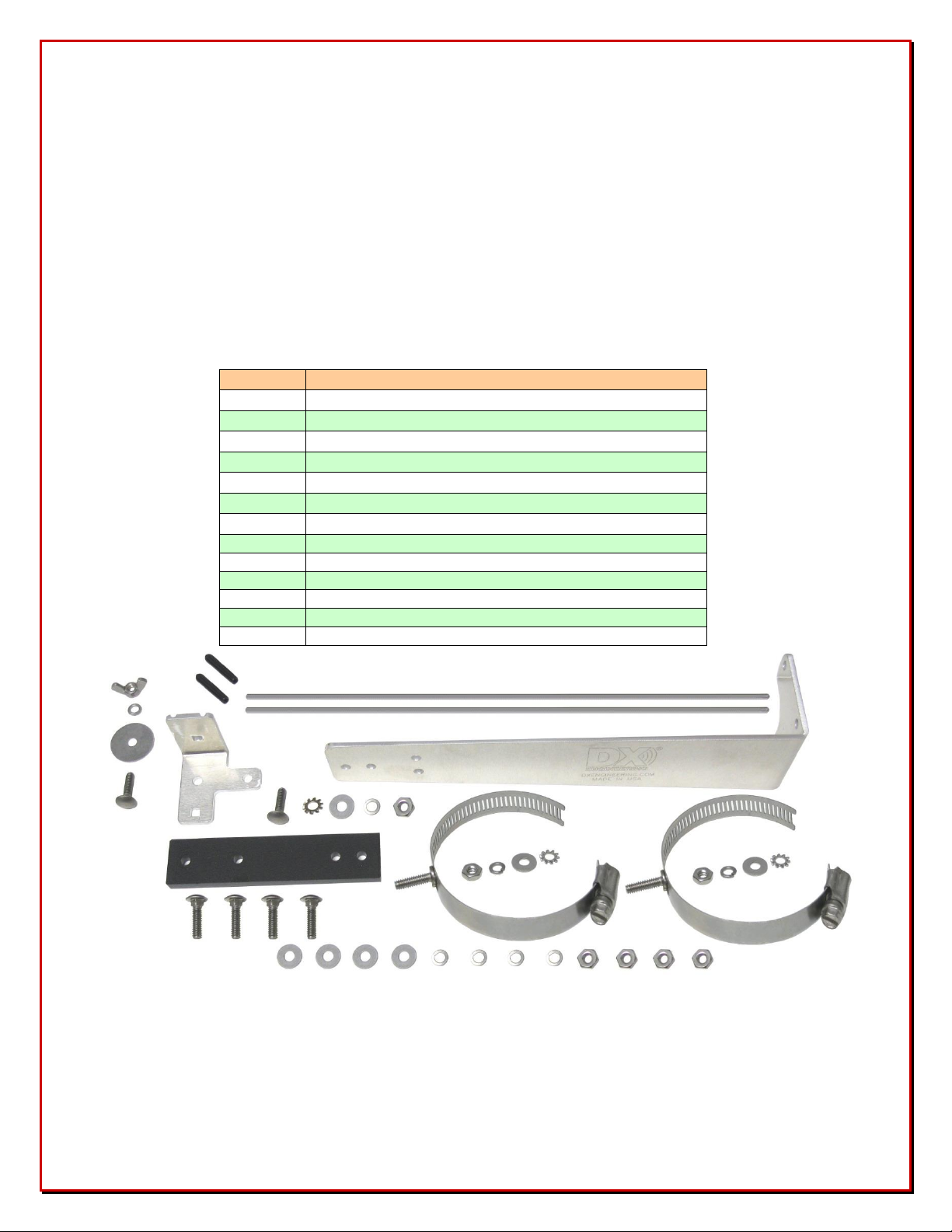
Included Materials
Pre-assembled 14 ga stranded, tin coated, FLEX-WEAVE™ 30 Meter element wire with
soldered ring terminals
Six Stainless Steel Band Clamps with Threaded Studs
Lower, Middle and Upper Laser Cut Stainless Steel Mounting Arms
Two 12 inch Hot Roz™ with Black Vinyl Covers for one end
Patented Serpentine Insulators (US Patent No. D534,905)
All Stainless Steel Hardware
Parts List
- 2 -
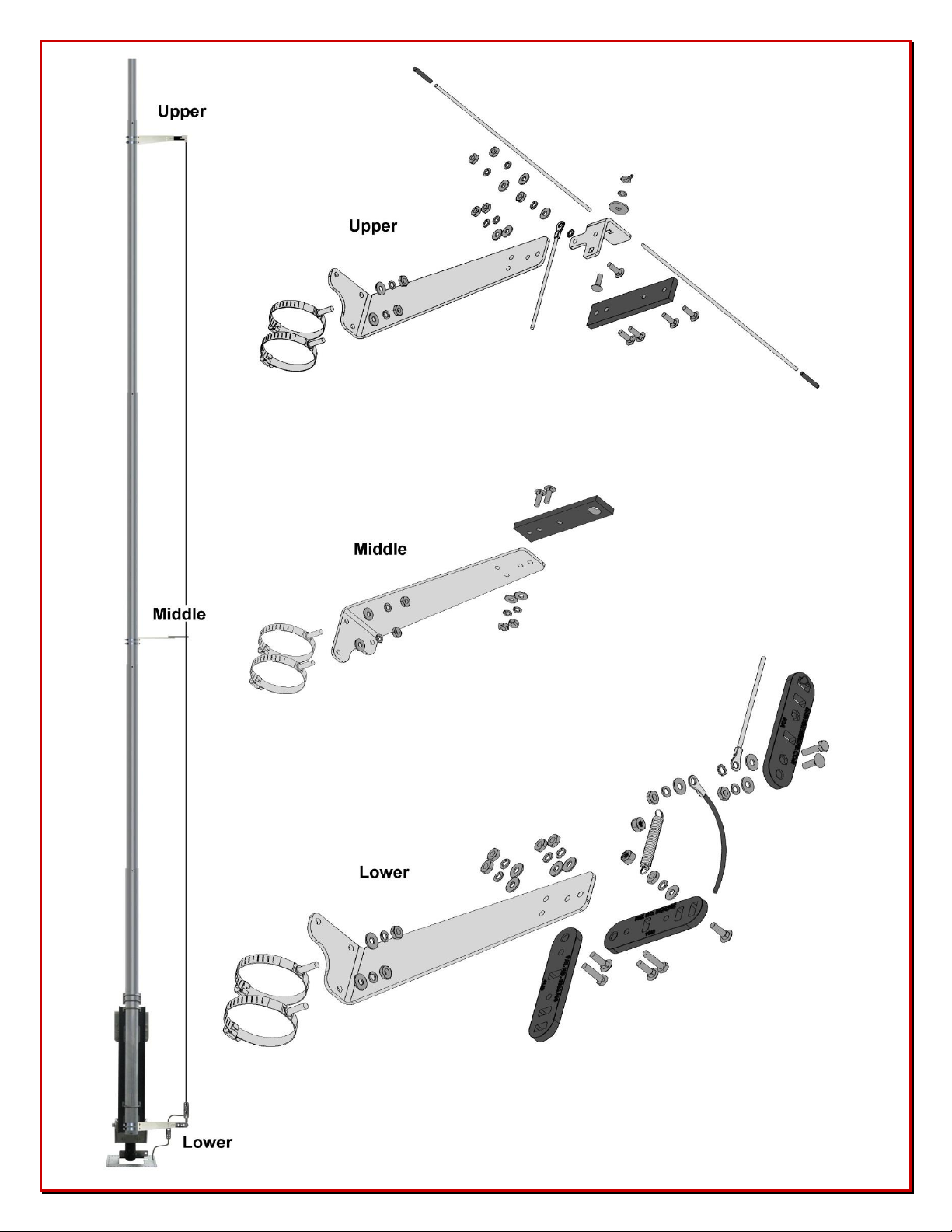
- Figure 1 -
Overall Exploded
Parts Drawing
- 3 -
Tools Required
Quantity
Upper Assembly Parts Description
1
Stainless Steel Laser Cut 30 Meter AOK Mounting Arm
1
30 Meter AOK Hot Rodz Bracket.
1
30 Meter AOK Insulated Bracket # 1 (4 holes all same size)
2
Stainless Steel Hot Rodz™, 12"
2
2.25" Studded Element Clamp w/ Stainless Steel Hardware
2
Black Plastic End Cap for Hot Rodz™
6
# 10-24 x 3/4" Stainless Steel Carriage Bolt
4
# 10 Stainless Steel Flat Washer
1
# 10 x 1" x 0.62" thick Stainless Steel Fender washer
6
# 10 Stainless Steel Split Washer
1
# 10 Stainless Steel External Star Washer
5
# 10-24 Stainless Steel Hex Nut
1
# 10-24 Stainless Steel Wing Nut
3/8" Nut Driver
5/16" Nut Driver
When installing stainless steel hardware, it is suggested that UMI-81343, UMI-81464, DXE-
NSBT8 or DXE-NMBT8 - Never-Seez or Anti-Seize be used to prevent thread galling.
Upper Assembly
1. The Upper assembly uses the following parts. Refer to Figure 1 for an exploded view.
Upper Assembly Parts
- 4 -
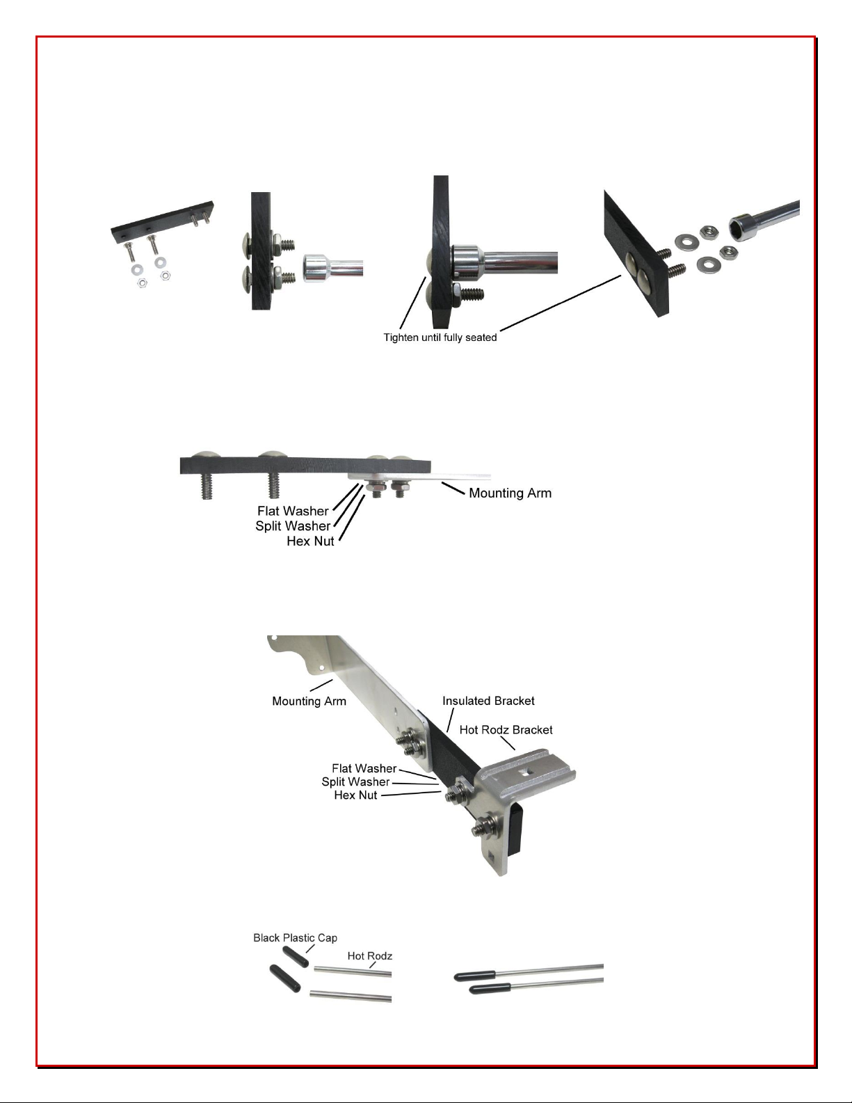
2. To install the four 3/4" carriage bolts into the 30 Meter AOK insulated bracket, use a flat washer
and hex nut. Tighten the nut until the carriage bolt is fully seated on the insulator. Once fully
seated, remove the hex head nut and washer. Install all four carriage bolts from the same side on
the insulator as shown in Figure 2.
Figure 2
3. Install the 30 Meter AOK insulated bracket onto the stainless steel laser cut 30 Meter AOK
mounting arm using two flat washers, split washers and hex nuts as shown in Figure 3.
Figure 3
4. Install the 30 Meter AOK Hot Rodz™ Bracket to the 30 Meter AOK insulated bracket as shown
in Figure 4 using two flat washers, split washers and hex nuts.
Figure 4
5. Install the black plastic end caps on the end of the 12" stainless steel Hot Rodz™ as shown in
Figure 5.
Figure 5
- 5 -

6. Install one 3/4" carriage bolt into the Hot Rodz™ bracket as shown in Figure 6 using one fender
washer, one split washer and one wing nut. Do not tighten.
Figure 6
7. Install the 12" Hot Rodz™ into the Hot Rodz™ bracket by loosening the wing nut, sliding the
Hot Rodz™ in place in the grooved areas. As shown in Figure 7, adjust the Hot Rodz™ so you
have each one extending approximately eight inches on either side. Tighten the wing nut. Do not
over tighten. During the tuning, the Hot Rodz™ will be adjusted equally either inward or
outward.
Figure 7
8. Install the two 2.25" studded band clamps to the stainless steel laser cut 30 Meter AOK
mounting arm as shown in Figure 8.
Figure 8
- 6 -

Middle Assembly
Quantity
Middle Assembly Parts Description
1
Stainless Steel Laser Cut 30 Meter AOK Mounting Arm
1
31 Meter AOK Insulated Bracket # 2
2
2.500" Studded Element Clamp w/ Stainless Steel Hardware
2
# 10-24 x 3/4" Stainless Steel Carriage Bolt
2
# 10 Stainless Steel Flat Washer
2
# 10 Stainless Steel Split Washer
2
# 10-24 Stainless Steel Hex Nut
1. The Middle assembly uses the following parts. Refer to Figure 1 for an exploded view.
Middle Assembly Parts
2. To install the two 3/4" carriage bolts into the 30 Meter AOK insulated bracket, use a flat washer
and hex nut. Tighten the nut until the carriage bolt is fully seated on the insulator. Once
fully seated, remove the hex head nut and washer. Install both carriage bolts from the same side
on the insulator as shown in Figure 9.
Figure 9
- 7 -

3. Install the 30 Meter AOK insulated bracket onto the stainless steel laser cut 30 Meter AOK
mounting arm using two flat washers, split washers and hex nuts as shown in Figure 10.
Figure 10
4. Install the two 2.5" studded band clamps to the stainless steel laser cut 30 Meter AOK mounting
arm as shown in Figure 11. (Note - This bracket is mounted to the studded band clamps
differently than the upper and lower brackets).
Figure 11
- 8 -

Lower Assembly
Quantity
Description
1
Stainless Steel Laser Cut 30 Meter AOK Mounting Arm
3
End Insulator - Polyamide Wire/rope connection (US Patent No. D534905)
1
Flex-Weave 30 Meter Wire Assembly, 233.00" with Soldered Ring Terminals
1
Wire Assembly, 23.50" Black PVC Insulated with #10 and 1/4" Soldered Ring Terminals
2
3.00" Studded Element Clamp w/ Stainless Steel Hardware
1
Stainless Steel Spring, 1.75"
2
# 10-24 x 3/4" Stainless Steel Carriage Bolt
2
# 10-24 x 1" Stainless Steel Carriage Bolt
3
# 10-24 x 5/8" Stainless Steel Hex Bolt
8
# 10 Stainless Steel Flat Washer
7
# 10 Stainless Steel Split Washer
1
# 10 Stainless Steel External Star Washer
6
# 10-24 Stainless Steel Hex Nut
2
# 10-24 Stainless Steel Nyloc Hex Nut
1. The Lower assembly uses the following parts. Refer to Figure 1 for an exploded view.
Lower Assembly Parts
2. Attach two end insulators to the mounting arm. Use one 3/4" carriage bolt and one 5/8" hex
head bolt along with a flat washer, split washer and hex nut for each end insulator as shown in
Figure 12.
Figure 12
- 9 -

3. The black wire (23.5") has two different sized ring terminals. Take the smaller ring terminal end
and loosely weave the wire through the second hole of end insulator as shown in Figure 13.
Figure 13
4. Assemble the last end insulator as shown in Figure 14 using the Flex-Weave (233") wire, the
black wire (#10 ring terminal end) and the stainless steel hardware Note the hex head bolt has a
recessed area the head fits slightly in during assembly. Note, when putting the stainless steel
spring on, use the Nyloc hex nut only tightened as shown in Figure 14. This allows the spring to
move, but not come off.
Figure 14
- 10 -

5. Connect the assembly from Step 4 to the lower assembly as shown in Figure 15. Install the 1"
carriage bolt, flat washer, split washer and hex nut. Then slide the spring in place and use the
Nyloc nut to hold the spring in place as shown.
Figure 15
6. Install the two 3" studded band clamps to the lower assembly as shown in Figure 16. Note the
orientation of the band clamp adjustment screws.
Figure 16
- 11 -

Attaching the 30 meter assemblies to the DXE-8040VA-1 vertical antenna
Before you start installation, measure the low SWR frequencies of your DXE-80/40VA-1 vertical
antenna on each band and record those measurements. This will assure your antenna is working
properly before adding the 30 meter kit and aid in making minor adjustments afterwards, if needed.
The orientation of the 30 meter kit on the DXE-8040VA-1 is important. The positioning of the 30
meter kit must be such that it does not interfere with the tilting of the antenna.
1. The lower 30 meter assembly is installed first while the DXE-8040VA-1 antenna is in the
upright position. The lower mounting bracket is attached to the base section using the stainless
steel studded band clamps as shown in Figure 16. With the clamps open, you can insert them
around the bottom aluminum element. Position the clamps just above the feedpoint as shown
and tighten in place.
Figure 16
2. Connect the black wire to the radial plate as shown in Figure 17. Adjust the black wire length
through the insulator to allow lowering the antenna and not interfering.
Figure 17
- 12 -

3. Lower the antenna (use a support so the antenna is not laying on the ground) and loosely install
Final positioning of the upper bracket should be done so the FLEX-WEAVE™ 30
meter wire is parallel to the DXE-8040VA-1. The spring should have tension to allow it
to keep the 30 meter wire taught when the antenna flexes in the wind.
Ensure the lower, middle and upper assemblies are in line and the 30 meter FlexWeave wire running between the lower and upper assemblies is snug, but not so tight
that it puts strain on the antenna element.
the middle assembly 12-1/2" above the junction of the 2.75" and 2.5" elements as shown in
Figure 18.
Figure 18
4. Loosely install the upper assembly 10-1/2" below the junction of the 2.25" and 2" elements as
shown in Figure 18.
5. Run the FLEX-WEAVE™ 30 meter wire attached to the lower assembly through the middle
assembly insulator large hole and attach it to the top bracket using the carriage bolt, flat
washers, star washer, split washer and nut as shown in Figure 19.
Figure 19
6. Once positioned properly, tighten the middle and upper assembly element clamps in place.
- 13 -
Tuning
An antenna analyzer is the best way to measure the SWR of the 30 meter assembly. The antenna
measurements should be made at the antenna base using a short (5 or 6 foot) piece of 50Ω coax
between the antenna and the analyzer. If you are too close to the antenna your presence can affect
the tuning, if you are too far, the coax length may act as a radial and resonate.
Raise the DXE-8040VA-1 to the full vertical position. Taking readings close to the antenna also
eliminates the possibility of a long or marginal feedline influencing the tuning or causing erratic
readings.
The 30 meter add-on kit electrically couples to the rest of the vertical but should not have influence
on the tuning of the 80 and 40 meter bands.
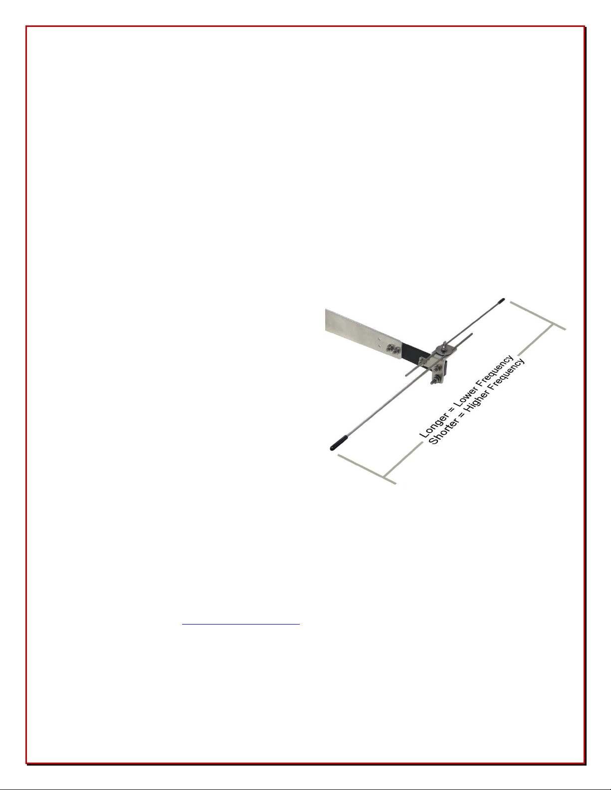
Adjustment of the 30 meter add-on kit SWR is done
by slightly loosening the wing nut holding the Hot
Rodz™ and adjusting the length of the Hot Rodz™.
Adjust both Hot Rodz™ equally longer to go lower
in frequency or equally shorter to go higher in
frequency.
Make adjustments in small steps.
Once tuning is complete, firmly tighten the Hot
Rodz™ in place using the wing nut.
Manual Updates
Every effort is made to supply the latest manual revision with each product. Occasionally a manual will be
updated between the time your DX Engineering product is shipped and when you receive it. Please check the
DX Engineering web site (www.DXEngineering.com) for the latest revision manual.
- 14 -

Notes:
- 15 -

Technical Support
If you have questions about this product, or if you experience difficulties during the installation, contact DX
Engineering at (330) 572-3200. You can also e-mail us at:
DXEngineering@DXEngineering.com
For best service, please take a few minutes to review this manual before you call.
Warranty
All products manufactured by DX Engineering are warranted to be free from defects in material and workmanship for a
period of one (1) year from date of shipment. DX Engineering’s sole obligation under these warranties shall be to issue
credit, repair or replace any item or part thereof which is proved to be other than as warranted; no allowance shall be
made for any labor charges of Buyer for replacement of parts, adjustment or repairs, or any other work, unless such
charges are authorized in advance by DX Engineering. If DX Engineering’s products are claimed to be defective in
material or workmanship, DX Engineering shall, upon prompt notice thereof, issue shipping instructions for return to
DX Engineering (transportation-charges prepaid by Buyer). Every such claim for breach of these warranties shall be
deemed to be waived by Buyer unless made in writing. The above warranties shall not extend to any products or parts
thereof which have been subjected to any misuse or neglect, damaged by accident, rendered defective by reason of
improper installation, damaged from severe weather including floods, or abnormal environmental conditions such as
prolonged exposure to corrosives or power surges, or by the performance of repairs or alterations outside of our plant,
and shall not apply to any goods or parts thereof furnished by Buyer or acquired from others at Buyer’s specifications.
In addition, DX Engineering’s warranties do not extend to other equipment and parts manufactured by others except to
the extent of the original manufacturer’s warranty to DX Engineering. The obligations under the foregoing warranties
are limited to the precise terms thereof. These warranties provide exclusive remedies, expressly in lieu of all other
remedies including claims for special or consequential damages. SELLER NEITHER MAKES NOR ASSUMES ANY
OTHER WARRANTY WHATSOEVER, WHETHER EXPRESS, STATUTORY, OR IMPLIED, INCLUDING
WARRANTIES OF MERCHANTABILITY AND FITNESS, AND NO PERSON IS AUTHORIZED TO ASSUME
FOR DX ENGINEERING ANY OBLIGATION OR LIABILITY NOT STRICTLY IN ACCORDANCE WITH THE
FOREGOING.
©DX Engineering 2017
DX Engineering®, DXE®, DX Engineering, Inc.®, Hot Rodz®, Maxi-Core®, DX Engineering THUNDERBOLT®, DX
Engineering Yagi Mechanical®, EZ-BUILD®, TELREX®, Gorilla Grip® Stainless Steel Boom Clamps, Butternut®,
SkyHawk™, SkyLark™, SecureMount™, OMNI-TILT™, RF-PRO-1B®, AFHD-4® are trademarks of PDS Electronics,
Inc. No license to use or reproduce any of these trademarks or other trademarks is given or implied. All other brands
and product names are the trademarks of their respective owners.
Specifications subject to change without notice.
- 16 -
 Loading...