

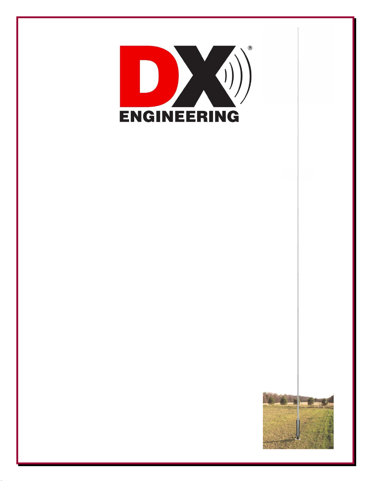
75/80 Meter
Full Size
Quarter-Wave
Vertical Antenna
DXE-7580FS-VA-2
US Patent No. 8,130,168
DXE-7580FS-VA-2-INS Revision 6e
© DX Engineering 2022
1200 Southeast Ave. - Tallmadge, OH 44278 USA
Phone: (800) 777-0703 ∙ Tech Support and International: (330) 572-3200
Fax: (330) 572-3279 ∙ E-mail: DXEngineering@DXEngineering.com

- 1 -
Table of Contents
Introduction
2
Features
2
Warning
3
Overhead Power Line Safety
3
Tools Required
3
Manual Updates and Information
3
Installation Sequence
4
Site Selection
4
Mounting Pipe
4
Coaxial Cable to Mounting Pipe
5
Radial System
5
Assembly Notes
6
Radial Plate to Mounting Pipe
6
Attaching Ground Radial Wires to the Radial Plate
7
Overall Pivot and Antenna Base Assembly Reference Drawing
8
Pivot Base and Lower Antenna Assembly
9
Mounting and using the Optional DXE-VRW-1 Manual Winch
16
General Information about Aluminum Tubing
19
Assembling the Vertical Sections
20
Mating the Vertical Elements to the Pivot Base Assembly
26
Feedline Connection
27
Optional Guy Rope and Anchor Installation
28
Tuning the Vertical
29
Optional DXE-VMN-1 Vertical Antenna Matching Network
29
Locking the Pivot Base
30
DXE-7580FS-VA-2 Part Lists
30
Pivot Base Assembly
30
Optional DXE-VRW-1 Manual Winch Assembly
31
Feedpoint Hardware
31
Vertical Elements Assembly
31
Additional Material Required but not Supplied
32
Suggested Parts Not Included
32
Optional Accessory Items
33
Technical Support
35
Warranty
35

- 2 -
Introduction
Congratulations on obtaining your DX Engineering DXE-7580FS-VA-2 Full size 75/80 Meter
Quarter-Wave Vertical Antenna. With this antenna you will have a high-performance vertical
antenna specifically for the 75/80 meter bands. The DX Engineering 68 foot vertical antenna
supplies the highest possible performance to achieve the strongest possible presence at your power
level and be competitive.
A FULL SIZE quarter-wave high-performance antenna that provides all the important design
details. The thick-wall 6061 sections provide you with a very stout antenna that can stay up with no
guying necessary and no worry on your part. When expecting a big storm the antenna can easily be
lowered with the supplied Heavy Duty Plus Stainless Steel Pivot Base (US Patent 8, 130,168) with
the optional hand winch.
A 2:1 SWR Bandwidth of 466 to 557 kHz depending on your radial field. Your internal tuner can
get SWR down to 1:1 on any DXing Frequency for maximum power transfer.
The DX Engineering DXE-7580FS-VA-2 is a slow taper 68 foot high vertical antenna system. The
vertical antenna is specifically designed to operate on 75/80 meters. Included with this antenna
system is a rugged heavy duty stainless steel pivot fixture for ease of assembly and adjustments.
Engineered with 6063 corrosion-resistant aluminum tubing, stainless steel mounting brackets and
stainless steel hardware, this antenna is very durable and attractive.
Features
Ultra-WIDE SWR Bandwidth and Unbeaten Gain
Highest Wind Ratings - High Strength 6063/6061 Tubing Manufactured to DX Engineering
Specifications
Easy Tilt Up and Down - Specially Manufactured Heavy Duty Stainless Steel Pivot Base
High Power Handling Capacity
No Rust - 100% Stainless Steel Tubing Clamps and Hardware
Reliability Second to None - Specially Manufactured Stainless and Aluminum Saddle
Clamps, Stainless Bolts and Precision Machining on each antenna
5 kW SSB and CW rated - unparalleled reliability
High Strength Heavy Duty Pivoting Base - US Patent No. 8,130,168
Ultra-rugged construction starts with 3 inch OD Aircraft Grade heavy wall tubing
Self supporting - will withstand steady-state winds in excess of 90 mph without guying
(guying required under extreme wind speed or ice conditions)
Massive Extren® channel insulator
Laser-cut high strength Stainless Steel brackets
The optional DXE-VRW-1 Manual Winch for easy one-person raising and lowering of the antenna
is available from DX Engineering. The DXE-VRW-1 winch can be moved between similar
antennas in a multi-antenna installation.

- 3 -
This antenna system requires the installation of a heavy duty mounting pipe set in concrete.
Specifically, 3" OD (max) high strength galvanized steel tubing with 0.250” minimum wall
thickness and 7’ minimum length, which is available from DX Engineering; part number DXE-
VGMT-3CG. A customer supplied 2-1/2" Schedule 80 pipe that has an outside diameter of 2.875"
is also suitable. Thirty seven inches of the mounting pipe should extend above ground level. Depth
of the mounting hole and amount of concrete is dependent on local soil type, condition and
antenna guying.
WARNING!
INSTALLATION OF ANY ANTENNA NEAR POWER LINES IS DANGEROUS
Warning: Do not locate the antenna near overhead power lines or other electric light or power
circuits, or where it can come into contact with such circuits. When installing the antenna, take
extreme care not to come into contact with such circuits, because they may cause serious injury or
death.
Overhead Power Line Safety
Before you begin working, check carefully for overhead power lines in the area you will be
working. Don't assume that wires are telephone or cable lines: check with your electric utility for
advice. Although overhead power lines may appear to be insulated, often these coverings are
intended only to protect metal wires from weather conditions and may not protect you from electric
shock
Keep your distance! Remember the 10-foot rule: When carrying and using ladders and other long
tools, keep them at least 10 feet away from all overhead lines - including any lines from the power
pole to your home.
Tools Required
Two 9/16" wrenches, (one of them should be open-end)
One 7/16" open end wrench
Two 3/4" wrenches
Medium size flat blade screwdriver or 5/16" & 1/4” nut drivers for the element clamps
Tape measure
Black Felt Tip marker
Manual Updates and Information
Every effort is made to supply the latest manual revision with each product. Occasionally a manual
will be updated between the time your DX Engineering product is shipped and when you receive it.
Please check the DX Engineering web site (www.dxengineering.com) for the latest revision manual.

- 4 -
Please - Take the time to read the entire manual before you start assembly. There are plenty of
pictures and drawings to see, and if you read the entire manual first, you'll get a better feel for the
overall construction methods described. Assembly is not difficult, but there are a number of parts
that must go together in a certain sequence to make assembly easier.
Installation Sequence
1. Site Selection
2. Mounting Pipe
3. Coaxial Cable to Mounting Pipe
4. Radial System
5. Pivot Base Assembly (US Patent No. 8,130,168)
6. Mounting Pivot Base to Mounting Pipe
7. Antenna Assembly
8. Tuning
Site Selection
Select a mounting location clear from power lines, structures and other antennas by a minimum of
78 feet (68 + 10 ft safety rule). Consider overhead power lines, utility cables and wires. The
further away the vertical is mounted from local noise sources or other metallic objects, which can
re-radiate noise and affect the tuning, radiation pattern and SWR, the better. Determine the direction
you want the antenna to pivot and make sure there is adequate clearance (at least 80 feet).
Mounting Pipe
DX Engineering has a galvanized Chromoly Steel mounting mast available - Part Number DXEVGMT-3CG is 3 inches OD, Chrome-Moly 4130 Steel Tubing, 100K PSI Min. Yield, 3 in. OD,
0.250 in. Wall, 7 ft. Length,

- 5 -
This mounting pipe must be permanently mounted in the ground, preferably in a concrete base 2
feet by 2 feet by 4 feet deep (with gravel below for drainage). The antenna system requires this type
of mounting to help withstand the lateral forces present on the
antenna during wind conditions and when operating the pivot
function. Make the hole deep enough to accommodate at least 4
feet of pipe and 4 to 6 inches of gravel at the bottom for drainage.
Set the mounting pipe on the gravel, use the concrete to fill
around the pipe per the concrete instructions. Fill the hole until
the concrete is level with the ground around it. Use a level on the
mounting pipe as you fill the hole to be sure the mounting pipe is
vertically straight.
Your location, landscape and ground conditions may require
different mounting solutions in order to have the steel
mounting pipe and the vertical antenna in a secure position.
Note: Galvanized steel, rather than aluminum, is much more
suitable for mounting in concrete. Aluminum will
quickly corrode due to incompatibility with the
materials used to make concrete.
Coaxial Cable to Mounting Pipe
The coaxial cable should be routed to the base of the antenna system and be buried below the radial
system. PVC Conduit pipe may be used to house the coaxial cable. Bury the cable 6" to 12" below
ground level.
Radial System
The use of a radial system is a key requirement for a high performance
quarter wave vertical antenna system. With a vertical antenna system,
the radials are the second half of the antenna. The radials contribute to
the radiation efficiency of the entire vertical antenna system.
At a minimum, 32 radials, each 65 feet long, should be used with this
antenna. DXE-RADW Radial Wire, a 14 gauge stranded copper with a
black relaxed PVC insulation wire is suggested for the best results.
The wire radials should placed as symmetrically as possible straight
from the feedpoint around the vertical antenna and spaced evenly,
regardless of how many radials are used. Do not cross or bunch any radial wires as this nullifies
their effectiveness. If you have limited space, put in as many straight radials as you can. The radials
must be connected to the shield of your feedline. The DXE-RADP-3 Stainless Steel Radial Plate is
an ideal optional item which provides an excellent system for attaching radial wires to your vertical
antenna system feedpoint.

- 6 -
Radial wires can be laid on the roots of the grass using DXE-STPL Radial Wire Anchor Pins to
hold them down. Using enough staples will ensure the wires will not be snagged by mowers,
people, or animals. Grass will quickly overgrow the radials and it will be virtually impossible to see
them. An article describing this process is available on the DX Engineering website in the Tech
Info section. Radials can also be buried just under the surface by using a power edger to make a slit
in the soil.
Assembly Notes
Note: JTL-12555 Jet-Lube™ SS-30 Anti-Oxidant must be used between all antenna
element sections. Jet-Lube™ SS-30 is an electrical joint compound to affect a substantial
electrical connection between metal parts such as telescoping aluminum tubing or other
antenna pieces. It ensures high conductivity at all voltage levels by displacing moisture and
preventing corrosion or oxidation.
Jet-Lube™ SS-30 must be used on all element clamps and stainless steel threaded hardware
to provide good electrical contact, prevent galling, allowing easier disassembly and to ensure
proper tightening.
Note: The following assembly instructions are based on using an optional DXE-
VGMT-3GC Mounting Pipe (referred to as 3” OD), with the optional DXEVR-1 Manual Winch, optional DXE-RADP-3 Radial Plate with one optional
DXE-SSVC-3P V Clamp, one optional DXE-UHF-FDFB-KIT SecureMount™ dual SO-239 Bulkhead Connector and one DXE-FP-WIREP Feedpoint Wire and Connector Assembly.
Radial Plate to Mounting Pipe
Place the optional DXE-RADP-3 Radial Plate over the 3" OD (maximum) mounting pipe. Attach
the Radial Plate to the mounting pipe using one DXE-SSVC-3P stainless steel V-Clamp. Allow
approximately one inch clearance between the bottom of the Radial Plate and the ground to allow
access to the radial wire mounting hardware (see Figure 1). Connections to the antenna will be
made via the optional DXE-UHF-FDFB-KIT SecureMount™ dual SO-239 bulkhead connector.
The DXE-RADP-3 Radial Plate comes with 20 sets of stainless steel hardware for mounting the
radial wires. It is suggested that 32 radial each 65 feet long be used, therefore additional DXE-
RADP-1HWK Radial Plate Wire Attachment Hardware Kits will be required.

- 7 -
Figure 1 - Optional DXE-RADP-3 Radial Plate Mounted to a 3" OD Mounting Pipe
Attaching Ground Radial Wires to the Radial Plate
Using the 20 sets of supplied 1/4" stainless steel hardware (Bolt, Star Washer, Flat Washer, Split
Washer, Nut) connect the optional ground radial wires to the DXE-RADP-3 Radial Plate as shown
below. Additional hardware kits are available (DXE-RADP-1HWK) that contain 20 sets of Radial
Plate Hardware.
There are optional DX Engineering Radial Wire Kits available. DXE-RADW-500K/BD contains a
500 foot spool of 14 gauge copper stranded wire with black PVC insulation, 20 Terminal Lugs and
100 Steel or Biodegradable Lawn Staples. The DXE-RADW-1000K/BD Radial Wire Kit contains
a 1,000 foot spool of 14 gauge copper stranded wire with black PVC insulation, 40 Terminal Lugs
and 200 Steel or Biodegradable Lawn Staples. RADW-20RT, -32RT or -65RT contain 20 each
radial wires with 1/4" terminal attached. These kits come in 20 Ft, 32 Ft or 65 Ft lengths.
Depending on the number of radial wires used, space them out evenly around the Radial Plate. The
Radial Plate will accommodate up to 60 radial wires (60 laser drilled holes), or up to 120 radials if
doubled up.
Radial Wire Pattern
Radial Wire Hardware Installation

- 8 -
Overall Heavy Duty
Pivot Base (US Patent No. 8,130,168)
Assembly Reference Drawing
The exploded view drawing
is for reference and shows
the overall Pivot Base
Assembly.

- 9 -
Pivot Base and Lower Antenna Assembly
1. Locate the heavy duty Extren® insulated channel.
There are 12 holes drilled in the insulated channel.
The top of the insulated channel is identified by two
holes located very near the top end.
2. Locate the stainless steel bottom hinge plate, backing plate, four carriage bolts, four 3/8" flat
washers, four 3/8" split lock washers and four 3/8" hex nuts. Assemble the bottom hinge to the
bottom of the heavy duty Extren® insulated channel as shown below.
3. Locate the stainless steel pivot base locking plate, backing plate, four carriage bolts, four 3/8"
flat washers, four 3/8" split lock washers and four 3/8" hex nuts. Assemble the pivot base
locking plate to the top of the heavy duty Extren® insulated channel as shown below.

- 10 -
4. Locate the stainless steel base side bottom hinge, two 1/2-13 x 1-1/4" long stainless steel hex
head bolts, two pivot bushings, four 1/2" x 1/4" stainless steel flat washers, two 1/2" stainless
steel split lock washers, and two 1/2-13 stainless steel hex nuts. Assemble the base side hinge
plate to the bottom hinge plate as shown below.
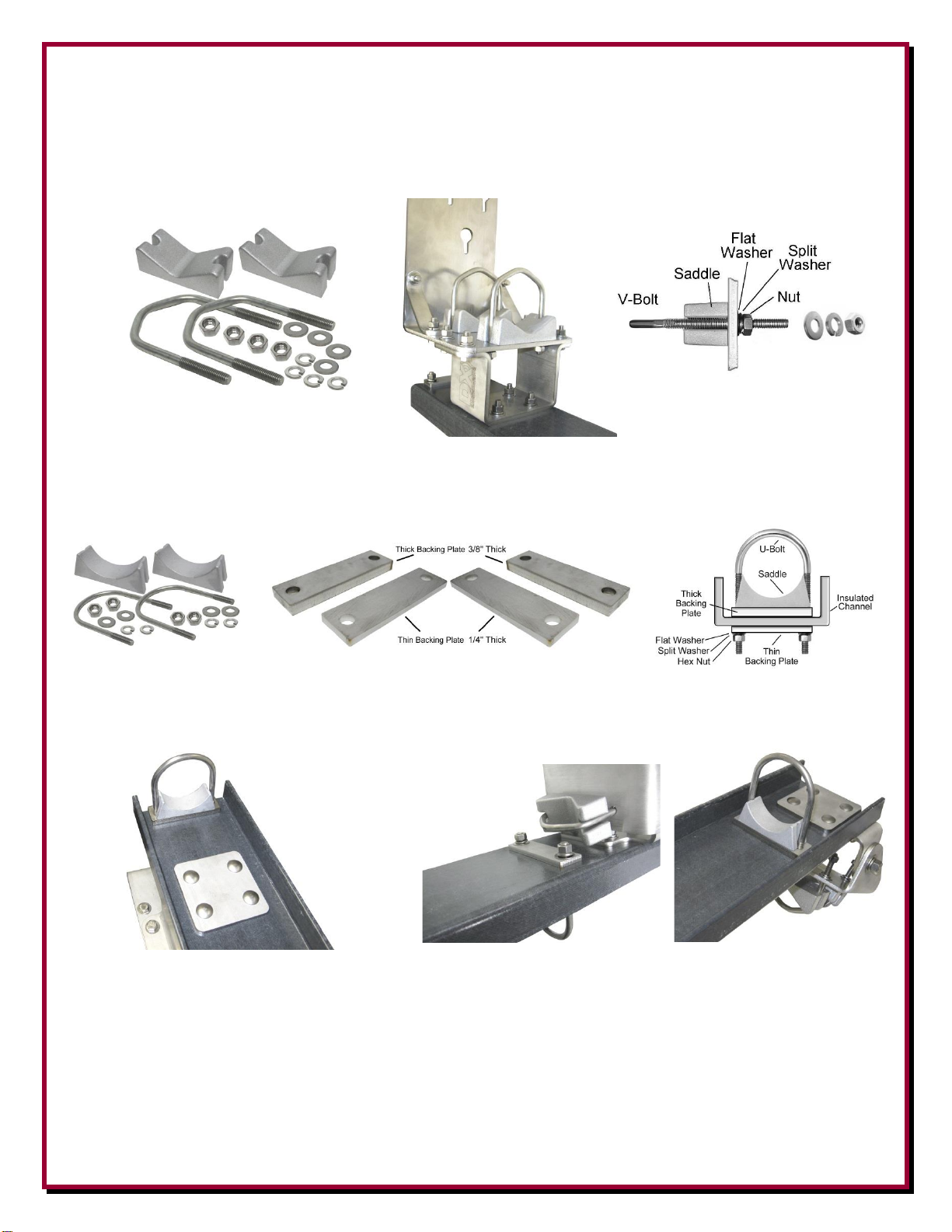
5. Locate two V-Saddle blocks, two stainless steel V-Bolts, four stainless steel 3/8" flat washers,
four stainless steel 3/8" split lock washers and four stainless steel 3/8-16 hex head nuts. Loosely
assemble (one or two threads beyond the end of the hex nuts) the two V-Bolts to the stainless
steel base side bottom hinge as shown below. The V-Bolts will be tightened in a later assembly
step.

- 11 -
6. Locate the stainless steel Pivot Base Winch Mount, two stainless steel Pivot Base Plate
Brackets, four 3/8-16 x 1-1/4" long stainless steel hex bolts, eight stainless steel 3/8" flat
washers, four stainless steel 3/8" split lock washers and four stainless steel 3/8-16 hex nuts.
Assemble the Pivot Base Plate Brackets to the Pivot Base Winch Mount as shown below.
7. Locate four 3/8-16 x 1-1/4" long stainless steel hex bolts, eight stainless steel 3/8" flat washers,
four stainless steel 3/8" split lock washers and four stainless steel 3/8-16 hex nuts. Mount the
Pivot Base Winch Mount assembly to the stainless steel Pivot Base Locking Plate.
Note: These four bolts are removed when using the pivoting function as described later in this
manual.
- 12 -
8. Locate two V-Saddle blocks, two stainless steel V-Bolts, four stainless steel 3/8" flat washers,
four stainless steel 3/8" split lock washers and four stainless steel 3/8-16 hex head nuts. Loosely
assemble (one or two threads beyond the end of the hex nuts) the two V-Bolts to the stainless
steel Pivot Base Winch Mount as shown below. The V-Bolts will be tightened in a later
assembly step.
9. Locate two thick stainless steel Backing Plates, two thin stainless steel Backing Plates, two
U-Bolt Saddle blocks, two stainless steel U-Bolts, four stainless steel 3/8" flat washers, four
stainless steel 3/8" split lock washers and four stainless steel 3/8-16 hex head nuts.
The two Thick Backing Plates (3/8”) are located next to the U-Bolt Saddles on the inside of the
insulated channel. The two Thin Backing Plates (1/4”) are used on the rear side of the insulated
channel.
Top of Insulated Channel Rear and Front views showing the U-Bolt located
Showing U-Bolt installed at the Bottom of the Insulated Channel
The Thick Spacer is on the front side The Thick Spacer is on the front side, the
The Thin Spacer is on the rear side Thin Spacer is on the rear side
Loosely assemble (one or two threads beyond the end of the hex nuts) the two U-Bolts and
associated hardware to the insulated mounting channel as shown above. The U-Bolts will be
tightened in a later assembly step.

- 13 -
10. Move the four V-Bolts out as far as they will go (these were put on loosely in steps 2 and 8).
Slide the entire assembly onto your mounting pipe. You want approximately 1 inch clearance
from the top of your mounting pipe to the bottom side of the winch mounting plate.
Position the base fixture in the position you pre-selected for the pivoting direction.
Tighten the V-Bolt clamp hardware evenly so the length of the exposed threads is
approximately equal. Any clamp should be tightened evenly from side-to-side with an equal
amount of thread above each nut.

- 14 -
11. Locate the 3" OD x 72", 0.120” wall thickness antenna bottom element
section. There are 4 holes drilled in this element section.
Four drilled holes at the top are used for mating to the next antenna
element section.
Loosen the previously installed U-Bolts (Step 9). Insert the 72"
Antenna Bottom Element Section into the antenna base section
through the upper and lower U-Bolts.
Position the single feedpoint hole at the bottom facing outward
as shown in the picture to the right.
The bottom of the 3" OD element tube should be even with the
bottom of the insulated channel as shown below.
Side View Front View
Tighten the lower and upper U-Bolt clamps hardware evenly so the length of the exposed
threads is approximately equal. Any clamp should be tightened evenly from side-to-side with an
equal amount of thread above each nut.

- 15 -
12. Locate the stainless steel Antenna Hook Mounting Plate, two U-Bolt Saddle blocks, two
stainless steel U-Bolts, four stainless steel 3/8" flat washers, four stainless steel 3/8" split lock
washers and four stainless steel 3/8-16 hex head nuts.
Loosely assemble (one or two threads beyond the end of the hex nuts) the two U-Bolts and
associated hardware to the antenna hook mounting plate as shown below. The U-Bolts will be
tightened in the next assembly step.
13. Loosen the U-Bolts enough to slide the Antenna Hook Mount assembly over the 3" OD antenna
lower element on the base assembly. Position the antenna hook mount approximately 1/2" above
the insulated channel as shown below.

- 16 -
14. Tighten the two U-Bolt clamps hardware evenly so the length of the exposed threads is
approximately equal. Any clamp should be tightened evenly from side-to-side with an equal
amount of thread above each nut.
15. Locate the 1/4-20 x 1" long stainless steel hex bolt, three 1/4" stainless steel external tooth lock
washers, two 1/4" stainless steel flat washers and two stainless steel 1/4-20 hex nuts. Install the
feedpoint hardware at the bottom of the 3" OD bottom element in the pre-drilled hole as shown
below.
Views showing the Feedpoint hardware installed
Mounting and using the Optional DXE-VRW-1 Manual Winch
1. Follow the instructions included with the optional DXE-VRW-1 - Manual Winch Add-On Kit
to prepare the Manual Winch for installation on the antenna base assembly.
2. Included with optional DXE-VRW-1 - Manual Winch Add-On Kit is the
stainless steel hardware for mounting the winch on the pivot base assembly.
The hardware includes three 3/8-16 x 1" long stainless steel hex bolts, six
stainless steel 3/8-16 flat washers and three 3/8-16 Stainless Steel Nyloc Nuts.
Loosely install the three sets of stainless steel hardware on the manual winch as shown below.
The hardware does not have to be removed
from the manual winch to either install or
remove the manual winch from the winch
mounting plate.

- 17 -
There are three holes with slots in the mounting bracket. The flat washers will fit through the
large holes. Once in place, push the winch inward (toward the antenna elements) allowing the
three bolts to go into the three slots. Tighten the hardware to hold the winch in place.
Connect the Hook from the manual winch strap to the Antenna Hook Mount as shown below.
To remove the winch, simply reverse this sequence.

- 18 -
3. To lower the antenna, ensure the winch hook is in the Antenna Hook Mount. Remove the four
bolts and hardware that hold the Pivot Lock Plate to the Pivot Base Winch Mount Plate. You
can now use the winch to pivot the antenna downward.
Four Bolts to be removed to allow for pivoting
4. Turn the crank on the manual winch to lower, or raise the antenna. After raising the antenna
completely, make sure you replace the four bolts that were removed in step 3. The manual
winch should be removed and stored when not in use to protect the gears and web strap from
weather and environmental effects.
Note: Sawhorses, chairs, or ladders should be used to support the vertical sections during
assembly with the pivot base and whenever the vertical is tilted down to allow easy
maintenance, or when making adjustments.

- 19 -
General Information about Aluminum Tubing
Note: JTL-12555 Jet-Lube™ SS-30 Anti-Oxidant must be used between all antenna element
sections. Jet-Lube™ SS-30 is an electrical joint compound to affect a substantial
electrical connection between metal parts such as telescoping aluminum tubing or
other antenna pieces. It ensures high conductivity at all voltage levels by displacing
moisture and preventing corrosion or oxidation. Jet-Lube™ SS-30 must be used on all
element clamps and stainless steel threaded hardware to provide good electrical
contact, prevent galling, allowing easier disassembly and to ensure proper tightening.
When assembling any telescoping aluminum tubing sections you should take the following steps:
1. Make sure the edges are smooth and not sharp. Deburring may be necessary, since burrs and
shavings can occur on seams as well as edges. All surfaces need to be completely smooth to
allow easy assembly of tubing sections.
Caution
Aluminum tubing edges can be very sharp.
Take precautions to ensure you do not get accidentally cut.
The raised particles and shavings that appear when the aluminum tubing is machined are
referred to as burrs, and the process by which they are removed is known as deburring.
Deburring is a finishing method used in manufacturing. DX Engineering aluminum tubing is
machine cut on both ends and machine slit on one end and you should further assure that there
are no ragged edges or protrusions.
Use the DXE-22166 Slim Grip Deburring Tool, or the DXE-22600 Deburring Tool with
Extending Handle and Extra Blades for this operation.
2. Clean the inside of the aluminum tubing to clear out any dirt or foreign material that would
cause the aluminum tubing sections to bind during assembly. Do not use any type of oil or
general lubricant between the aluminum tubing sections. Oils or general lubricants can cause
poor electrical connections for radio frequencies.
3. Clean the outside of the aluminum tubing to clear any dirt or foreign material that would cause
the clamps to malfunction during assembly.
4. The use of JTL-12555 Jet-Lube™ SS-30 is highly recommended. Jet-Lube™ SS-30 is an
electrical joint compound which effects a substantial electrical connection between metal parts
such as telescoping aluminum tubing or other antenna pieces. Using Jet-Lube™ SS-30 assures
high conductivity at all voltage levels by displacing moisture and preventing corrosion or
oxidation.
5. When assembling the aluminum tubing sections, ensure the area is clear of grass, dirt or other
foreign material that could cause problems during assembly of the closely fitted telescoping
sections.

- 20 -
Assembling the Vertical Sections
Note: JTL-12555 Jet-Lube™ SS-30 Anti-Oxidant must be used between all antenna element
sections. Jet-Lube™ SS-30 is an electrical joint compound to affect a substantial
electrical connection between metal parts such as telescoping aluminum tubing or
other antenna pieces. It ensures high conductivity at all voltage levels by displacing
moisture and preventing corrosion or oxidation. Jet-Lube™ SS-30 must be used on all
element clamps and stainless steel threaded hardware to provide good electrical
contact, prevent galling, allowing easier disassembly and to ensure proper tightening.
The vertical sections of the DXE-7580FSVA-2 consists of custom engineered 6063 corrosionresistant aluminum tubing ranging in size from 3" OD to .25" OD. The 3" OD section has already
been mounted in the Pivot Base Assembly.
It is suggested that the vertical elements be laid out in a line according to size on a flat surface for
ease of assembly. Once all the parts are assembled, the vertical sections should be supported with
either saw horses, chairs or other suitable structures for assembly.
When all the vertical element sections are assembled, they will be mated to the Pivot Base
Assembly.
Locate the parts needed for the vertical element assembly:
Vertical Elements Assembly - Parts List
QTY
Description
QTY
Description
1
3.00" OD x 72" long, .120" wall, 5 drilled holes
2
DXE-ECL-0500 Stainless Steel Element Clamp
1
2.75" OD x 48" long, .120" wall, 8 drilled holes
1
DXE-ECL-0625 Stainless Steel Element Clamp
1
2.5" OD x 72" long, .120" wall, 8 drilled holes
2
DXE-ECL-0875 Stainless Steel Element Clamp
1
2.25" OD x 72" long, .120" wall, 8 drilled holes
1
DXE-ECL-1000 Stainless Steel Element Clamp
1
2" OD x 72" long, .120" wall, 4 drilled holes, slits on one end
3
DXE-ECL-1250 Stainless Steel Element Clamp
1
1.75" OD x 72" long, .120" wall, slits on one end
3
DXE-ECL-1500 Stainless Steel Element Clamp
1
1.5" OD x 72" long, .120" wall, slits on both ends
3
DXE-ECL-1750 Stainless Steel Element Clamp
1
1.25" OD x 72" long, .058" wall, slits on one end
There is a 1.125" OD x 36" long tube inside and riveted in place
2
DXE-ECL-2000 Stainless Steel Element Clamp
2
1/4" x 2-3/4" long Stainless Steel Hex Head Bolt
1
1.125" OD x 36" long, .058" wall, slits on one end
2
1/4" x 3" long Stainless Steel Hex Head Bolt
1
1" OD x 36" long, .058" wall, slits on one end
2
1/4" x 3-1/4" long Stainless Steel Hex Head Bolt
1
0.875" OD x 36" long, .058" wall, slits on one end
2
1/4" x 3-1/2" long Stainless Steel Hex Head Bolt
1
0.75" OD x 36" long, .058" wall, slits on one end
16
1/4" Stainless Steel Flat Washer
1
0.625" OD x 36" long, .058" wall, slits on one end
8
1/4" Stainless Steel Nyloc Hex Nut
1
0.50" OD x 72" long, .058" wall, slits on one end
1
0.375" OD x 36" long, .058" wall, slits on one end
1
0.25" OD x 72" long, .035" wall
1
Black Vinyl Cap for 1/4" OD Tube

- 21 -
Note: The 3" OD x 72" long, 0.120" wall thickness base antenna section has already been installed
on the Pivot Base Assembly.

- 22 -
Figure A-1 below is an overall layout of all the vertical elements with hardware shown for
reference. The 3" OD element which is already mounted on the base pivot assembly is shown for
reference.
- 24- Figure A-1

- 23 -
Assemble the 2.5" OD element to the 2.75" OD element using the two stainless steel 3-1/4" long
1/4" bolts, four stainless steel flat washers and two 1/4" stainless steel Nyloc nuts as shown in
Figure A-2. Make sure you insert the 2.75” OD tube into the correct end of the 2.5” OD section the holes at each end are drilled differently. When tightening the bolt and Nyloc nut, tighten them
enough to hold, but not tight enough to deform the aluminum elements.
Figure A-2.
The following drilled sections are drilled to match the next size, so make sure you have the correct
ends matched up (holes aligned).
Repeat the above step to mate the 2.25" OD element to the 2.5" OD element using the 3" long 1/4"
bolts. Reference Figure A-3.
Repeat the above step to mate the 2" OD element to the 2.25" OD element using the 2-3/4" long
1/4" bolts. Reference Figure A-3.
Figure A-3

- 24 -
Using a tape measure and felt tip pen all of the slit tubing elements need to be marked as follows for
an overlap as shown in Figure A-4.
Figure A-4

- 25 -
Using Figure A-1, place the element clamps over the appropriate tubing.
When tightening the element clamps, install them approximately 1/4" to 1/2" below the end of
the slit tube with the worm tightening drive as shown in Figure A-5, located between two of
the four slits.
Figure A-5
NOTE: At three locations, there are three element clamps installed. Two same sized clamps are
on the element with the slit, the third clamp is located right next to the larger element. See
Figure A-6.
Figure A-6
To avoid damage to the element clamps, do not over-tighten them.
When the antenna elements are completely assembled and mated to the base section, the
overall length measured from the top of the antenna to the feedpoint on the base section
should be 847” (70 Feet, 7 inches) prior to tuning.

- 26 -
Mating the Vertical Element to the Pivot Base Assembly
1. To lower the antenna, ensure the winch hook is in the Antenna Hook Mount. Remove the four
bolts and hardware that hold the Pivot Lock Plate to the Pivot Base Winch Mount Plate. You
can now use the winch to pivot the antenna downward.
Four Bolts to be removed to allow for pivoting
2. Locate the 3-1/4" long 1/4"
bolts, four stainless steel flat
washers and two 1/4"
stainless steel Nyloc nuts.
Align the 3" OD base section
element with the assembled
vertical elements. Slide the
2.75" element section into the
3" OD base element section
aligning the 4 holes.
- 27 -
3. Assemble the 2.75" OD element to the 3" OD element using the two stainless steel 3-1/4" long
1/4" bolts, four stainless steel flat washers and two 1/4" stainless steel Nyloc nuts as shown
below. When tightening the bolt and Nyloc nut, tighten them enough to hold, but not tight
enough to deform the aluminum elements.
DANGER: When raising or lowering the vertical antenna make sure you have not
inadvertently located the antenna underneath power lines.
Residential power lines are often less than 40' high.
Contact With Any Power or Utility Lines Can Be Lethal !
In areas where there is a high atmospheric static condition (areas prone to precipitation or snow
static) this antenna (as with all antennas) will build up a static charge. When working on the
antenna, especially in the raised position, you may want to ground the antenna to bleed off any
static before touching the antenna. (Obviously, you also do not want RF present on the antenna
when touching it). The optional DXE-VMN-1 Vertical Matching Network (described on the next
page) will also act as a constant static bleed for your vertical antenna in areas where precipitation
static or snow static is present.
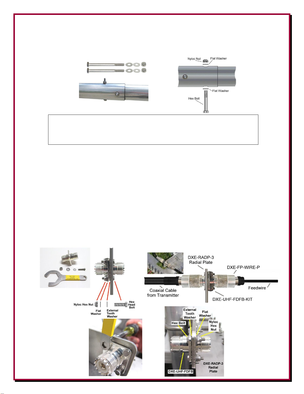
Feedline Connection
The easiest way to make a reliable feedline connection using customer supplied coaxial cable is
using the DXE-RADP-3 Radial Plate with the DXE-UHF-FDFB-KIT SecureMount™ dual SO-239
Bulkhead Mount Connector with the DXE-FP-WIRE-P Feedpoint Wire Connector Assembly
should be used as shown below.
Using the
SecureMount™
Bulkhead
Connector and the
Feedpoint Wire
Assembly

- 28 -
Optional Guy Rope and Anchor Installation
Even through this antenna is rated for windy conditions, guying is recommended on any vertical
antenna especially in areas where it is very windy, susceptible to wind gusts or ice conditions. Four
screw-in earth anchors and sufficient antenna rope are available as model DXE-GUY1000-KIT to
allow guying of the antenna at up to three levels in four directions. Rule-of-thumb engineering
suggests the distance of the anchors from the antenna base should be equal to the height of the
highest guy level. This provides a 45-degree guy angle. The guy ropes should be fastened just
above an element clamp using a DX Engineering Guy Ring or non-slip knot as shown below.
The set of four earth anchors (DXE-EA15-4P) may be augured into the ground approximately 35 to
50 feet from the antenna base to fasten the guy ropes. When you install the earth anchors, make sure
one of them is placed exactly opposite the direction toward which the antenna will tilt over. The
others should then be evenly spaced. You may find it easier to first install and raise only the
sections of tubing up to the lower set of guy ropes. This will allow you to establish the correct
length and tie off the ropes. Then, you can disconnect the guy rope toward the rear and, leaving the
others fastened, lower the partial sections for final assembly. The remaining ropes will provide
stability as the antenna assembly is raised. The example below shows one set of guy ropes being
used. The ropes should be snug, but not tight. The antenna will move slightly in the wind and that is
acceptable.
Earth Anchor

- 29 -
Tuning the Vertical
When the antenna elements are completely assembled and mated to the base section, the overall
length measured from the top of the antenna to the feedpoint on the base section should be 847” (70
Feet, 7 inches) prior to tuning. This allows you to make adjustments in the overall length to tune
the antenna to the center frequency you desire using the following information.
It’s best to use a good quality antenna analyzer for determining antenna resonance. Use the X=0 and
+/- j0 readings to determine the resonant frequency. The SWR will be adjusted by the impedance
matching assembly mounted at the feed point once the vertical is resonant at the desired frequency.
The DXE-7580FS-VA-2 should resonate at approximately 3.5 MHz with the recommended ground
radial system installed and the vertical dimensions described in this manual. Resonance is adjusted
by the length of the vertical element sections. To raise the frequency, slide the top .025” OD
element into the .375” OD element.
If you are having trouble achieving resonance, make sure the element section lengths are correct.
Make sure you have at least 16 radials (32 are better), 65 feet long, symmetrically placed around the
vertical. Our test vertical employed 32 radials, 65 feet long. The difference in resonance from 16 to
32 radials is about 30 kHz.
The antenna resonant frequency may be centered at any point by merely adjusting the overall
length. To raise the base resonant frequency, shorten the element tubing stack.
As a rule of thumb, one foot of length should be approximately 50 kHz in frequency. A shorter
antenna length = higher frequency and a longer antenna length = lower frequency.
Optional DXE-VMN-1 Vertical Antenna Matching Network
The DXE-VMN-1 Vertical Antenna Matching Network is custom designed for use with
base-fed quarter wave resonant vertical antenna systems. In some vertical antenna
installations with excellent radial systems, achieving the best SWR on a resonant
vertical for 80 meters may be difficult without some means of adjusting feedpoint
impedance. The DXE-VMN-1 allows easy adjustment for lowest SWR.
As an added benefit, since the DXE-VMN-1 it will also act as a static bleed for your monoband
vertical antenna in areas where precipitation static or snow static is present.
Refer to the DXE-VMN-1 manual for more details.
- 30 -
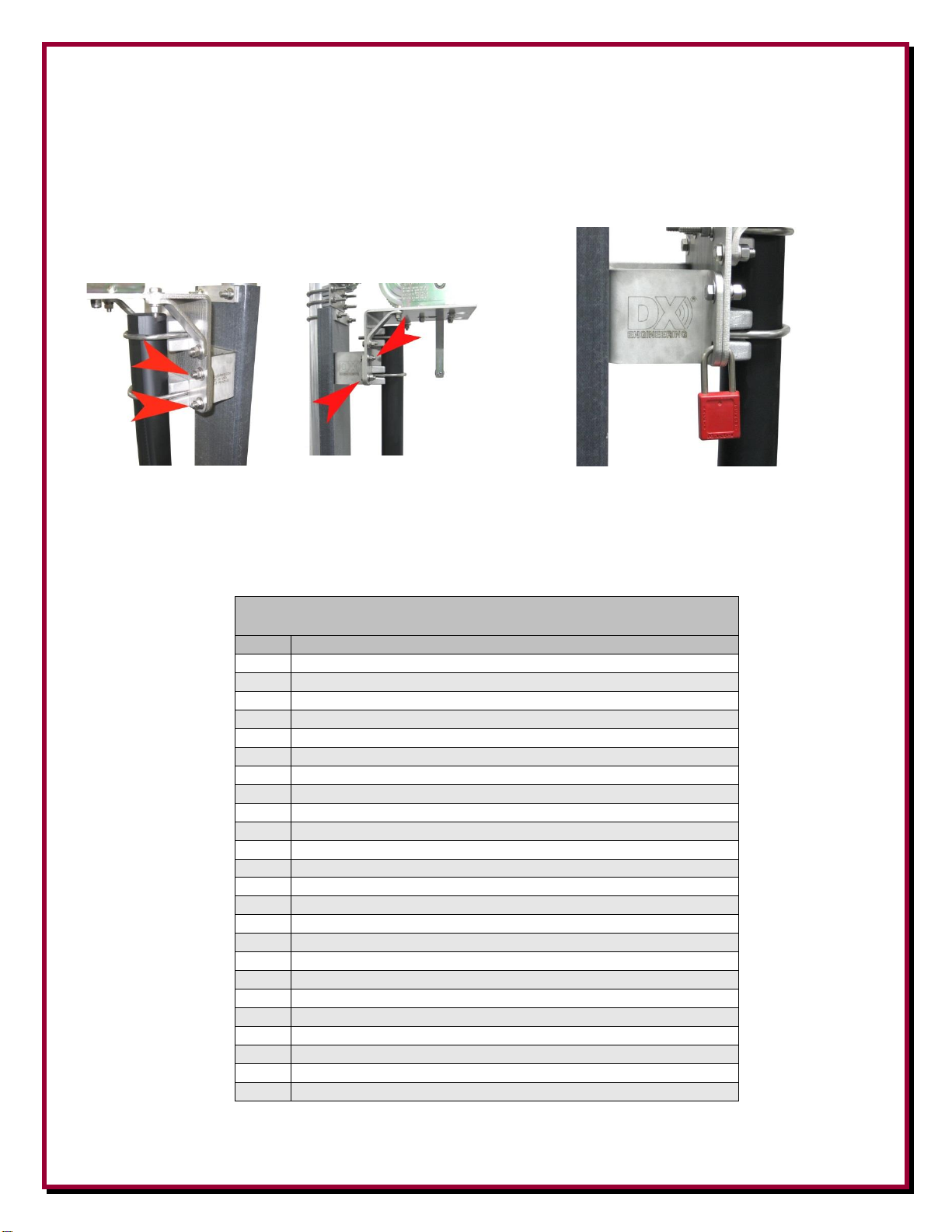
Locking the Pivot Base
To help prevent accidental pivoting, ensure the four pivot locking bolts are in place and properly
secured. Additionally, you may replace one of the bolts with a padlock to further prevent tampering
or accidental pivoting as shown below.
Ensure all four Pivot Locking Bolts are in place
Padlock used in place of one Pivot Locking Bolt
DXE-7580-VA-2 Parts List
Pivot Base Assembly - US Patent No. 8,130,168
QTY
Description
1
Base Side Bottom Hinge
1
Antenna Side Bottom Hinge
2
Bottom Hinge Bushing
1
Heavy Duty Antenna Insulator Channel
2
Saddle Backing Plate 1/4” thick
1
Antenna Pivot Hook Mount
1
Pivot Base Winch Mount
2
Pivot Base Plate Bracket
1
Pivot Base Lock Plate
2
Backing Plate, Square
2
Saddle Spacer Plate 3/8"
4
3" Stainless U-Bolt
4
3" Cast Saddle Clamp
40
3/8" Flat Washer
32
3/8" Split Lock Washer
32
3/8-16 Nut
8
3/8-16 x 1.25" Long, Hex Head Cap Screw
4
2"-3" Cast V-Saddle
4
2"-3" 3/8"-16 V-Bolt
8
3/8-16 x 1-1/2" Long Stainless Steel Carriage Bolt
2
1/2-13 x 1-1/4" Long Stainless Steel Hex Head Cap Screw
4
1/2" x 1-1/4" Stainless Steel Washer
2
1/2" Stainless Steel Lock Washer
2
1/2-13 Stainless Steel Nut

- 31 -
Optional DXE-VRW-1 Manual Winch Assembly
QTY
Description
1
1500 Pound Exposed Gear Hand Winch with Brake
1
Custom Polyester web strap with Hook, 2" x 15 Ft
1
3/8-16 x 3-1/2" long Grade 8 Hex Head Bolt
4
3/8-16 Stainless Steel Nyloc Nut
3
3/8-16 x 1" long Stainless Steel Hex Bolt
8
3/8-16 Stainless Steel Flat Washer
Feedpoint Hardware
QTY
Description
3
1/4" External Star Washer
1
1/4-20 x 1" long Stainless Steel Hex Head Cap Screw
2
1/4" Stainless Steel Flat Washer
2
1/4" Stainless Steel Nut
Vertical Elements Assembly
QTY
Description
1
3.00" OD x 72" long, .120" wall, 5 drilled holes
1
2.75" OD x 48" long, .120" wall, 8 drilled holes
1
2.5" OD x 72" long, .120" wall, 8 drilled holes
1
2.25" OD x 72" long, .120" wall, 8 drilled holes
1
2" OD x 72" long, .120" wall, 4 drilled holes, slits on one end
1
1.75" OD x 72" long, .120" wall, slits on one end
1
1.5" OD x 72" long, .120" wall, slits on both ends
1
1.25" OD x 72" long, .058" wall, slits on one end
There is a 1.125" OD x 36" long tube inside and riveted in place
1
1.125" OD x 36" long, .058" wall, slits on one end
1
1" OD x 36" long, .058" wall, slits on one end
1
0.875" OD x 36" long, .058" wall, slits on one end
1
0.75" OD x 36" long, .058" wall, slits on one end
1
0.625" OD x 36" long, .058" wall, slits on one end
1
0.50" OD x 72" long, .058" wall, slits on one end
1
0.375" OD x 36" long, .058" wall, slits on one end
1
0.25" OD x 72" long, .035" wall
1
Black Vinyl Cap for 1/4" OD Tube
2
DXE-ECL-0500 Stainless Steel Element Clamp
1
DXE-ECL-0625 Stainless Steel Element Clamp
2
DXE-ECL-0875 Stainless Steel Element Clamp
1
DXE-ECL-1000 Stainless Steel Element Clamp
3
DXE-ECL-1250 Stainless Steel Element Clamp
3
DXE-ECL-1500 Stainless Steel Element Clamp
3
DXE-ECL-1750 Stainless Steel Element Clamp
2
DXE-ECL-2000 Stainless Steel Element Clamp
2
1/4" x 2-3/4" long Stainless Steel Hex Head Bolt
2
1/4" x 3" long Stainless Steel Hex Head Bolt
2
1/4" x 3-1/4" long Stainless Steel Hex Head Bolt
2
1/4" x 3-1/2" long Stainless Steel Hex Head Bolt
16
1/4" Stainless Steel Flat Washer
8
1/4" Stainless Steel Nyloc Hex Nut
Note: This antenna system is normally shipped in several boxes. The hardware parts maybe in more
than one box. The part lists listed above are arranged for ease of assembly.

- 32 -
Additional Material Required, but not Supplied:
DXE-VGMT-3CG -Antenna Mounting Pipe - 3” OD x 7 Feet long 1/4” Wall thickness -
Galvanized Chromoly Steel mounting pipe.
Concrete - For mounting pipe installation (see text for detailed suggestions)
Feedline Connection - Use the D DXE-UHF-FDFB-KIT SecureMount™ dual SO-239
Bulkhead Mount Connector with the DXE-FP-WIRE-P Feedpoint Wire Connector Assembly
in conjunction with the optional DXE-RADP-3 Radial Plate and a customer supplied wire and
ring terminal (see text for suggestions).
Suggested Parts Not Included
DXE-VRW-1 - Manual Winch Add-on Raising Kit
Manual winch add-on kit for the High Performance DX Engineering vertical antennas. The tilt fixtures for these
antennas are equipped to accept the winch directly. Allows easy raising and lowering of tall antennas - may be
easily moved from one antenna to another in multi-antenna arrays.
DXE-RADP-3 - Radial Plate (patented):
Made from Laser Cut Stainless Steel with 20 Sets of Stainless Steel Radial Attachment Hardware. The DX Engineering
Radial Plate is meant for those of you having a vertical antenna and want an easy, neat and effective way to connect
those essential radial wires to your antenna system for the highest efficiency and strongest signals.
DXE-SSVC-3P - Stainless Steel V-Clamp for 2 to 3 inch steel pipe
This V-Clamp is made in one size that fits Steel tubing or pipe from 2'' to 3'' OD as used in antenna construction. The
supplied V-bolt is long enough to attach tubing to thick plates and is made with anti-corrosive properties. The special
Stainless Steel saddle has serrated teeth will clamp to the pipe securely by biting into the surface. For this reason, it is not
recommended for softer aluminum tubing or pipe. U-Bolt thread dimensions: 3/8-16 x 1.75". V-bolt and saddle made
from high-strength 18-8 stainless steel
DXE-RADP-1HWK - Radial Plate Wire Attachment Hardware Kit
Additional 20 Sets of ALL Stainless Steel Radial Hardware for use with the DX Engineering Stainless Steel Radial Plate.
(20) 1/4'' Bolts - (20) 1/4'' Nuts - (20) 1/4'' Flat Washers
(20) 1/4'' Split Washers - (20) 1/4'' Star Washers
DXE-225RT-20 - Ring terminal 16-14 Wire Gauge, 1/4" hole/20 Pack
\his is a set of 20 ring terminals for AWG #14 to 16 wire with a clearance hole for a 1/4" bolt. These are the same crimp
terminals supplied with the DXE Radial Wire Kits for #14 Radial and Antenna Wire.
DXE-FP-WIRE-P - Feedpoint Wire and Connector Assembly
DX Engineering Feedpoint Wire and Connector Assemblies provide a new and unique method of feeding an antenna radiating
element. A ring terminal with a 1/4 in. hole is crimped and soldered to a 12 in. long insulated 14 AWG stranded copper
wire, with weather-protective heat shrink tubing. The Feedpoint wire is terminated to the center pin of a UHF male PL259 with special insulating sleeves and weather-sealing heat shrink. This assembly is intended to be used with a double
female bulkhead connector, mounted into the Radial Plate, for use on an HF vertical antenna. The wire and connector
combination allows for the complete weather sealing of a single wire feedpoint, while properly terminating the feedline
shield to the radial system or ground point of the antenna system.

- 33 -
JTL-12555 Jet-Lube™ SS-30 Pure Copper Anti-Seize
Jet-Lube™ SS-30 Pure Copper Anti-Seize is the top choice of engineers and technicians in government, industry and leading Amateur
Radio contest stations, for protecting mechanical assemblies of aluminum tubing, general hardware and copper grounding
systems. On bonded metal surfaces Jet-Lube™ SS-30 assures electrical and RF conductivity while preventing oxidation
and corrosion. Surpassing the capabilities of other aluminum anti-oxidants, the wide temperature range of Jet-Lube™ SS30 prevents long-term drying and caking, and allows easy disassembly and effortless cleaning of parts. An
environmentally preferred thread lubricant and conductive termination compound, Jet-Lube™ SS-30 helps keep your
equipment in serviceable condition. It contains a high concentration of copper flakes, a requirement for heavy loads or
compression; controlled frictional characteristics allow the surfaces of nuts and bolts to be tightened to their design torque
specifications. This anti-seize product assures full hydraulic efficiency by allowing the metal surfaces to slide over each
other without damaging metal-to-metal contact. Jet-Lube™ SS-30 is also designed to work as a similar and dissimilar
component between two metal surfaces to prevent seizing and galvanic action. The SS-30 compound formula improves
conductivity and ground continuity - and will not melt in high temperatures.
Jet-Lube™ SS-30 Pure Copper Anti-Seize Features include:
* Meets MIL-PRF-907E spec
* K-factor: 0.13
* Service rating: -65 degrees F (-54 degrees C) to 1800 degrees F (820 degrees C)
* SS-30 Resistivity (ohm-CM x 108) 5
* This product is limited to domestic UPS Ground shipping only
DXE-UHF-FDFB-KIT - Silver Plated Female SecureMount™ Bulkhead Connector - Dual SO-239
The DX Engineering Silver Plated Female SecureMount™ Bulkhead Connector is a high-quality silver-plated connector that provides
a positive, permanently secure connection for your coaxial cable. The two-sided SO-239 female connector has a superior silverplated body with silver contacts to ensure the best performance for any application. The SecureMount™ flange, which employs four
mounting screws, means that the bulkhead connector won't work loose like those with concentric nuts and washers. Once mounted to
any panel or bulkhead, the flanged bulkhead connector will provide the best possible connection and stay that way. Additionally,
when using our Radial Plate, Tower Leg Brackets or SO-239 Mounting Brackets, the SecureMount™ Bulkhead Connectors are the
best way to bond your coax to ground this side of Cad-Welding! Unlike many common nickel-plated bulkhead connectors, our silverplated SecureMount bulkhead connectors have no air space within their midpoint. This area of solid and superior PTFE dielectric
between the center conductor and body maintains constant impedance and ultimate performance.
Description: Bulkhead mount, UHF jack to UHF jack (SO-239)
Body Material: Brass
Body Plating: Silver
Body Style: Flanged Dual Female SO-239
Contact Plating: Silver
Frequency Range: DC - 500 MHz
Dielectric: PTFE
Impedance: 50 ohms
Includes Stainless Steel Hardware Kit for mounting
DXE-RADW-65RT Pre-Assembled, 65 foot Radial Wires, w/ 1/4" ring Terminals, 20 Pack
The DXE-RADW-65T Radial Wire Kit include the highest quality 14 gauge stranded copper wire with a relaxed black PVC
insulation for easy installation of your radial system. This allows fast and easy installation of your radial ground system. The
stranded wire and relaxed insulation mean that the wire will lay flat as you place it on the ground - easy to install! The twenty 65 foot
pre-cut radial wires include 1/4" ring terminals professionally crimped on one end for quick and easy attachment to the radial
plate. This Radial Wire Kit is designed for users of vertical antenna systems which have the need for a high quality radial system for
optimum antenna performance. The 1/4" ring terminals are machine crimped for maximum grip. Soldering is not required for
strength, but is recommended if installed in corrosive environments such as salt spray.
Packed 20 Radial Wires per package
14 gage, stranded copper wire
Black relaxed PVC insulation
1/4" Ring Terminal professionally crimped on each Radial Wire
DXE-STPL-100BD - Radial Wire Staple, Biodegradable, 3", 100 pack
DX Engineering DXE-STPL-100BD is a 100-pack of 3” biodegradable anchors that are produced from recycled PLA
(Polylactide Resin). Depending on the weather conditions, they will degrade in about a year. They are easily installed
and will hold radial wires in place until lawn roots overtake them - and then disappear. Ecologically friendly!

- 34 -
DXE-RADW - 500K or 1000K Radial Wire Kits and Components
To achieve optimal performance with a ground-mounted vertical, install as many radials as possible. These bulk radial wire kits
use insulated wire that is UV resistant, hard to see and lays down easily, unlike the wire that is commonly available at the big box
stores. It will last much longer in contact with soil than bare wire.
The DXE-RADW- 500K or 1000K kit provide everything you will need to build the perfect radial system!
500/1000 ft. spool of 14 AWG, stranded copper wire with vinyl insulation
20/40 lugs
100/200 radial wire anchor pins- Eliminating the need to bury your radials!
Build up to 20/40 radials, 25 feet long
DXE-RADW-500K
Bulk Radial Wire Kit, 500 ft Spool of Wire, 20 Lugs, 100 Staples
DXE-RADW-1000K
Bulk Radial Wire Kit, 1000 ft Spool of Wire, 40 Lugs, 200 Staples
DXE-RADW-500KBD or 1000KBD - Bulk Radial Wire Kits and Components
To achieve optimal performance with a ground-mounted vertical, install as many radials as possible. These bulk radial
wire kit use insulated wire that is UV resistant, hard to see and lays down easily, unlike the wire that is commonly
available at the big box stores. It will last much longer in contact with soil than bare wire. The biodegradable anchors
allow easy installation of radial wires, and will degrade and disappear in a year or so when they are no longer needed.
The DXE-RADW-500 or 1000KBD kit provide everything you will need to build the perfect radial system!
500/1000 ft. spool of 14 AWG, stranded copper wire with vinyl insulation
20/40 lugs
100/200 biodegradable radial wire anchor pins- Eliminating the need to bury your radials!
Build up to 20/40 radials, 25 feet long
DXE-RADW-500KBD
Bulk Radial Wire Kit, 500 ft Spool of Wire, 20 Lugs, 100 Biodegradable Staples
DXE-RADW-1000KBD
Bulk Radial Wire Kit, 1000 ft Spool of Wire, 40 Lugs, 200 Biodegradable Staples
DXE-STPL - Radial Wire Anchor Pins, 100/pack - No need to bury your radials!
DX Engineering Radial Wire Anchor Pins are perfect for fastening radials below the grass line to eliminate the risk of damaging your
radials during lawn maintenance.
100 count - 6'' Pins
11-Gauge
DXE-STPL-100P
Radial Wire Anchor Pins, 100/pack
DXE-STPL-300P
Radial Wire Anchor Pins, 300/pack
SUM-900031 - Automatic Wire Stripper/Crimper/Cutter, 24-10 Ga.
Our DX Engineering wire stripper uses a spring-loaded design to make quick work of wires ranging from 24 to 10 gauge. Just insert
the wire, squeeze the handle, and listen for the click. That’s the sound of another perfect wire stripping job
performed in about 2 seconds- a fraction of the time it takes your pocket knife to do the same job. An adjustable
wire length guide helps you make uniform strips, and a built-in wire cutter and crimper helps you complete your
wiring job.
Spring-loaded design
Strips wires ranging from 24 to 10 gauge
built-in wire cutter and crimper
DXE-T001 - DX Engineering SO-239 Connector Installation Tool Kit
This DX Engineering SO-239 connector installation tool kit offers an easier installation of chassis or bulkhead mount SO-239 coaxial
connectors. Having the right tools can make all of the difference in your shack, and this handy DXE tool provides
you with a special dual-use stainless steel wrench, plus a multipurpose 6-in-1 screwdriver/nut driver tool. One end
of the wrench is a 3/4 in. semi-box wrench with a pass-through for coaxial cable--perfect for tightening the larger
nuts used to mount bulkhead connectors. The other end is a 3/16 in. box wrench for tightening mounting nuts with
SO-239 hardware. You'll receive six combinations - two Phillips heads, two flatheads, and a 1/4 in. nut driver and
a 5/16 in. nut driver, which store in the handle of the screwdriver. The added SO-239 wrench is ideal for use with
the DXE-UHF-FDFB-KIT - Silver Plated Female SecureMount™ Bulkhead Connector.

- 35 -
3M Temflex™ 2155 Rubber Splicing Tape
Conformable self-fusing rubber electrical insulating tape. It is designed for low voltage electrical insulating and moisture
sealing applications. For outdoor use, it should be protected from UV deterioration with an overwrap of Scotch
®
Super
33+.
Scotch® Super 33+
Highly conformable super stretchy tape for all weather applications. This tape provides flexibility and easy handling for all
around performance. It also combines PVC backing with excellent electrical insulating properties to provide primary
electrical insulation for splices up to 600V and protective jacketing. Both tape products are available from DX Engineering.
DXE-VMN-1 - Vertical Antenna Matching Network
The DXE-VMN-1 Vertical Antenna Matching Network is custom designed for use with base-fed quarter wave resonant vertical
antenna systems. In some vertical antenna installations with excellent radial systems, achieving the best SWR on a
resonant vertical for 80 meters may be difficult without some means of adjusting feedpoint impedance. The DXE-
VMN-1 allows easy adjustment for lowest SWR. The DXE-VMN-1 Vertical Antenna Matching Network will aid in
tuning a low impedance antenna to the minimum SWR in the customer selected portion of the 80 meter band. The #12
AWG coil wire is tin-nickel plated for high power handling, corrosion resistance, ease of soldering and long term
reliability. As an added benefit, the DXE-VMN-1 will also act as a static bleed for your resonant vertical antenna in
areas where precipitation or snow static is present. The Vertical Matching Network may be installed between ground
and the feedpoint of any quarter wave base-fed vertical antenna - including mobile antennas. It CANNOT be used on
non-resonant antenna such as a 43 foot vertical.
Technical Support
If you have questions about this product, or if you experience difficulties during the installation,
contact DX Engineering at (330) 572-3200. You can also e-mail us at:
DXEngineering@DXEngineering.com
For best service, please take a few minutes to review this manual before you call.
Warranty
All products manufactured by DX Engineering are warranted to be free from defects in material and workmanship for a period of one
(1) year from date of shipment. DX Engineering’s sole obligation under these warranties shall be to issue credit, repair or replace any
item or part thereof which is proved to be other than as warranted; no allowance shall be made for any labor charges of Buyer for
replacement of parts, adjustment or repairs, or any other work, unless such charges are authorized in advance by DX Engineering. If
DX Engineering’s products are claimed to be defective in material or workmanship, DX Engineering shall, upon prompt notice
thereof, issue shipping instructions for return to DX Engineering (transportation-charges prepaid by Buyer). Every such claim for
breach of these warranties shall be deemed to be waived by Buyer unless made in writing. The above warranties shall not extend to
any products or parts thereof which have been subjected to any misuse or neglect, damaged by accident, rendered defective by reason
of improper installation, damaged from severe weather including floods, or abnormal environmental conditions such as prolonged
exposure to corrosives or power surges, or by the performance of repairs or alterations outside of our plant, and shall not apply to any
goods or parts thereof furnished by Buyer or acquired from others at Buyer’s specifications. In addition, DX Engineering’s warranties
do not extend to other equipment and parts manufactured by others except to the extent of the original manufacturer’s warranty to
DX Engineering. The obligations under the foregoing warranties are limited to the precise terms thereof. These warranties provide
exclusive remedies, expressly in lieu of all other remedies including claims for special or consequential damages. SELLER
NEITHER MAKES NOR ASSUMES ANY OTHER WARRANTY WHATSOEVER, WHETHER EXPRESS, STATUTORY, OR
IMPLIED, INCLUDING WARRANTIES OF MERCHANTABILITY AND FITNESS, AND NO PERSON IS AUTHORIZED TO
ASSUME FOR DX ENGINEERING ANY OBLIGATION OR LIABILITY NOT STRICTLY IN ACCORDANCE WITH THE
FOREGOING.
©DX Engineering 2022
DX Engineering®, DXE®, DX Engineering, Inc.®, Hot Rodz®, Maxi-Core®, DX Engineering THUNDERBOLT®, DX Engineering
Yagi Mechanical®, EZ-BUILD®, TELREX®, Gorilla Grip® Stainless Steel Boom Clamps, Butternut
®
, SkyHawk™, SkyLark™,
SecureMount™, OMNI-TILT™, RF-PRO-1B®, AFHD-4® are trademarks of PDS Electronics, Inc. No license to use or reproduce
any of these trademarks or other trademarks is given or implied. All other brands and product names are the trademarks of their
respective owners.
Specifications subject to change without notice.
 Loading...