

Dwyer Instruments WDPM-002, WDPM Series, WDPM-005, WDPM-010, WDPM-020 Specifications-installation And Operating Instructions
...Page 1
Bulletin TE-WDPM
2
-21/64
[
59.28]
39/64
[15.59]
1
-1/64
[
25.80]
3
-17/64
[
82.77]
2
-21/32
[
67.31]
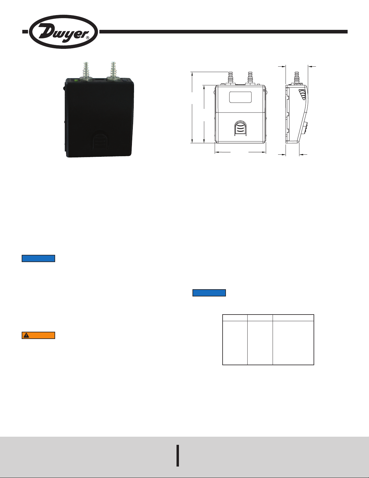
Series WDPM Wireless Differential Pressure Module for UHH
Specifications - Installation and Operating Instructions
The Series WDPM Wireless Differential Pressure Module transmits
measurements to the Model UHH handheld to view pressure drop across filters,
tatic pressure in ducts, and velocity pressures from pitot tubes or air flow stations.
s
hen using it with a pitot tube or air flow measuring station, the measurement can
W
e calculated to read directly in air velocity or volumetric air flow. The module
b
mounts in the holder on the back of the handheld, or in an optional mounting
bracket.
Wireless modules can take measurements from at least 50 feet away from the
base unit. An LED flashes on the top of the module to let the customer know when
the module communicates with the handheld, as well as when the module’s battery
is low. The battery is rechargeable via the mini-USB connector on the top of the
module.
CHARGING BATTERY
NOTICE
When the charge of the battery is almost used up, the LED on the module of the
wireless probe will turn solid red. There is approximately 5 minutes of battery life
left at this point. If the module is not already paired to the base unit, it will not pair
while in low battery condition.
Step 1: Plug the mini-USB connector end of the cable into the top of the module.
Step 2: Plug the USB connector end of the cable into the port on the charger or PC
(LED on the charger and the module should both light up).
Step 3: The LED on the module will turn off when fully charged.
Step 4: Remove USB cable from the module and the charger or PC.
WARNING
Inc. approved charging device in a well ventilated area away from any flammable
materials or gases. Do not incinerate the battery. Only charge between 32 to 113°F
(0 to 45°C).
It is required before the initial use of the module to fully charge
the battery for 12 hours.
Lithium ion batteries are very volatile and can cause a fire if
punctured or severely damaged. Only use a Dwyer Instruments,
SPECIFICATIONS
Service: Non-corrosive dry gases.
etted Materials: Consult factory.
W
ccuracy: ±0.5% FS span @ 25°C (includes non linearity, hysteresis, and non
A
epeatability).
r
Pressure Limits: See Table 1.
Temperature Limits:
Compensated: 32 to 140°F (0 to 60°C);
Process/Ambient: 14 to 140°F (-10 to 60°C).
Thermal Effects: ±0.01% FS/°F (±0.02% FS/°C).
Battery Charging Limits: 32 to 113°F (0 to 45°C).
Power Requirements: 3.7 V YT562447 lithium ion battery, installed functionally,
user replaceable.
Wireless Distance: At least 50´ (15 m).
Weight: 2.5 oz (70.87 g).
Connections: Two barbed connections for use with 1/8˝ (3.18 mm) or 3/16˝ (4.76
mm) ID tubing.
Agency Approvals: CE (not while charging), RoHS, FCC compliant.
NOTICE
If desired, it can be operated with USB powered cables less
than 3 m in length when connected to the charger or PC.
Model
WDPM-002
WDPM-005
WDPM-010
WDPM-020
WDPM-030
WDPM-100
WDPM-200
WDPM-400
Range
±2 in w.c.
±5 in w.c.
±10 in w.c.
±20 in w.c.
±30 in w.c.
±100 in w.c.
±200 in w.c.
±400 in w.c.
Table 1: Maximum Pressure
Maximum Pressure
10 psi
10 psi
10 psi
20 psi
20 psi
15 psi
45 psi
45 psi
DWYER INSTRUMENTS, INC.
P.O. BOX 373 • MICHIGAN CITY, INDIANA 46360, U.S.A. Fax: 219/872-9057 e-mail: info@dwyer-inst.com
Phone: 219/879-8000 www.dwyer-inst.com
Page 2
AIRING WIRELESS MODULES
P
. Turn on Model UHH Universal Handheld by pressing the button.
1
. Press the and buttons to scroll through the menu headings at the top of the
2
display.
3. When PROBE is highlighted, hit the button to access the probe menu.
4. Press to scroll through the sub-menu headings. The current selected parameter
ill be highlighted in yellow.
w
. When PAIRING MODE is highlighted, hit the button to access the pairing mode.
5
. Turn on the wireless module to be paired. After a period of up to 15 to 20 seconds,
6
he UHH screen will update with the information about the wireless module just turned
t
on.
7. Press the button to scroll through the available probes and modules. The current
selected probe or module will be highlighted in yellow.
. When desired probe or module to be paired is highlighted, hit the button to pair
8
he probe. Once it is paired, it will be removed from the list automatically.
t
. Once all the desired probes and modules are paired, press button.
9
0. Repeat step 9 to go back to the home screen and begin readings.
1
NOTICE
ELECTING A PROBE OR MODULE
S
n order to cycle through the probes or modules that are paired to the Model UHH
I
Universal Handheld, press the or buttons while displaying probe data.
SETTINGS
When using the Series WDPM Wireless Differential Pressure Module, the base unit
an display differential pressure, air velocity or air flow. The settings allow users to
c
elect which parameter to display in addition to the engineering units and
s
easurement range. To access the setting menus:
m
1. Press the or arrows to scroll through the menu headings at the top of the
display.
2. When PROBE is highlighted, hit the button to access the probe menu.
3. Press the arrow to scroll through the sub-menu headings. The currently selected
parameter will be highlighted in yellow.
Pressure / Flow / Velocity Selection
1. When sub-menu TYPE (next to Pressure) is highlighted, hit the button to
access the settings for the sub-menu.
2. Press the arrow to scroll through the parameters. The currently selected
parameter will be highlighted in yellow.
3. When DISPLAY is highlighted, press the button and pressure, velocity or vol.
flow will be highlighted.
4. Pressing the or buttons will scroll between pressure, velocity and vol. flow.
5. Once the desired selection is made, press button.
Units Selection
1. When sub-menu TYPE (next to Pressure) is highlighted, hit the button to
access the settings sub-menu.
2. Press the arrow to scroll through the parameter headings. The currently selected
parameter will be highlighted in yellow.
3. When UNITS is highlighted, press the button and the currently selected units
will be highlighted.
4. Pressing the or buttons will cycle through the available units.
5. Once the desired selection is made, press button.
f a module does not appear, power the module down, then
I
ower it back on.
p
rea Adjustment (Only when Display is set to Volumetric Flow)
A
. When sub-menu TYPE (next to Pressure) is highlighted, hit the button to
1
ccess the settings sub-menu.
a
2. Press the arrow to scroll through the parameter headings. The currently selected
parameter will be highlighted in yellow.
3. When AREA is highlighted, press the button to enter a new sub-menu that
llows selection of the shape of the duct, engineering units in which the duct is
a
easured, and the dimensions of the duct.
m
. Press the arrow to scroll through the parameter headings. The currently selected
4
arameter will be highlighted in yellow.
p
5. When the desired menu is highlighted, press the button and the current value
of the parameter will be highlighted.
6. Pressing the or buttons will cycle through the available options for each
arameter.
p
. Once the desired selection is made, press button.
7
. After all of the area parameters are made, press button.
8
K-Factor Adjustment (Only When Display is set to Volumetric Flow or Velocity)
1. When sub-menu TYPE (next to Pressure) is highlighted, hit the button to
access the settings sub-menu.
. Press the arrow to scroll through the parameter headings. The currently selected
2
arameter will be highlighted in yellow.
p
. When K-FACTOR is highlighted, press the arrow and the selected velocity pick-
3
up device will be highlighted.
4. Pressing the or arrow will cycle through the available velocity pick-up devices,
or allow for a manual K-factor to be set.
5. Once the desired selection is made, press button.
orrection Coefficient Adjustment (Only When Display is set to Volumetric Flow
C
r Velocity)
o
1. When sub-menu TYPE (next to Pressure) is highlighted, hit the button to
access the settings sub-menu.
2. Press the arrow to scroll through the parameter headings. The currently selected
parameter will be highlighted in yellow.
3. When CORRECTION is highlighted, press the arrow and the current correction
coefficient will be highlighted.
4. Pressing the or arrow will increase or decrease the value of the correction
coeffecient.
5. Once the desired selection is made, press button.
Zero / Span / Reset Adjustments (Only when pressure is the display selection)
The zero setting will set the differential pressure being measured to zero, and should
only be pressed with no pressure on either the high or low pressure port. The span
setting will set the differential pressure to the upper limit of the factory programmed
range and should only be pressed with that amount of pressure being sourced to the
pressure ports. The reset parameter will restore the calibration back to the factory set
values.
1. When sub-menu TYPE (next to Pressure) is highlighted, hit the button to
access the settings sub-menu.
2. Press the arrow to scroll through the parameter headings. The currently selected
parameter will be highlighted in yellow.
3. When ZERO, SPAN, or RESET is highlighted, press the arrow and SET will be
highlighted.
4. Pressing the arrow will attempt to set the zero, span, or reset and will ask for
the user to wait until the calibration is set. A FAIL message will be displayed if the unit
can not perform the function asked, and DONE will be flashed if the function was
performed successfully. If fail is displayed, press the button again to retry.
5. Once the desired function is completed, press arrow.
Page 3
OGGING MEASUREMENTS
L
he UHH series can log the data being measured either a single point at a time or
T
y continuously logging at a user defined sample rate. When the trigger is selected
b
o be a single point at a time, pressing the power button on the module or the store
t
button on the handheld will store a reading into the currently open file until the user
creates a new file. If there is not a file open, the handheld will ask to create one.
For manual trigger, the power button on the module or the store button on the base
nit will start the logging, but the logging will end after a user selected duration or
u
hen the power button on the module or stop button on the handheld is depressed.
w
hen the trigger is set for event, the user will select the upper and lower limit of a
W
ange and select whether the logging should take place while the measurements
r
are within or outside of the range. The handheld can also record up to 2 minutes
before the event (pre-trigger) and up to 24 hours after the event (post-trigger). If the
measurements don’t match the trigger event, a minimum data capture time can be
et.
s
ccessing Log Settings
A
1. Press the or arrows to scroll through the menu headings at the top of the
display.
2. When LOG is highlighted, hit the button to access the log menu.
3. Press the or arrows to scroll through the sub-menu headings. The currently
elected parameter will be highlighted in yellow.
s
. When the sub-menu RATE is highlighted, hit the button to set the sampling
4
ate.
r
5. Use the and arrows to select the desired sampling rate.
6. Once the desired sampling rate is selected, press the arrow.
7. When the sub-menu FILE FORMAT is highlighted, hit the button to choose
the file type.
. Use the and arrows to toggle between CSV and TSV file formats.
8
. Once the desired file format is selected, press the arrow.
9
0. When the sub-menu Media is highlighted, hit the button to choose where to
1
save the files.
11. Use the and arrows to toggle between internal memory (INT) and the
SD card, if present.
12. Once the desired location is selected, press the arrow.
13. When the sub-menu TRIGGER is highlighted, hit the button to access the
trigger settings sub-menu.
14. Press the arrow to scroll through the parameter headings. The currently
selected parameter will be highlighted in yellow.
IRELESS GUIDELINES IN ACCORDANCE WITH FCC:
W
hanges not expressly approved by Dwyer Instruments, Inc. could void the user's
C
uthority to operate the equipment.
a
This product complies with FCC OET Bulletin 65 radiation exposure limits set forth
for an uncontrolled environment.
ursuant to FCC 15.21 of the FCC rules, changes not expressly approved by
P
wyer Instruments, Inc. might cause harmful interference and void the FCC
D
uthorization to operate this product.
a
Canadian Government Guidelines:
Operation is subject to the following two conditions: (1) This device may not cause
harmful interference and (2) this device must accept any interference received,
ncluding interference that may cause undesired operation.
i
NFORMATION TO THE USER
I
Power Output: 6 mW
Operating Frequency: 2.4 GHz
Operating Channel: 11
Operating Mode: IEEE 802.15.4, Zigbee, Direct Sequence Spread Spectrum
ata Rate: Up to 250 kbps
D
ntended Use: Industrial/commercial HVAC
I
ntenna Connection: Internal only, non-tunable
A
MAINTENANCE/REPAIR
Upon final installation of the Series WDPM, no routine maintenance is required.
The Series WDPM is not field serviceable and should be returned if repair is
eeded. Field repair should not be attempted and may void warranty.
n
ARRANTY/RETURN
W
Refer to “Terms and Conditions of Sale” in our catalog and on our website. Contact
customer service to receive a Return Goods Authorization number before shipping
the product back for repair. Be sure to include a brief description of the problem,
plus any additional application notes.
Selecting Trigger Type
1.When the sub-menu TRIGGER is highlighted, hit the arrow and the currently
selected trigger type will be highlighted
2. Press the or arrows to cycle through the available trigger types.
3. Once the desired selection is made press the arrow.
Viewing Stored Files
1. Press the or arrows to scroll through the menu headings at the top of the
display.
2. When LOG is highlighted, hit the button to access the log menu.
3. Press the or arrow to scroll through the sub-menu headings. The currently
selected parameter will be highlighted in yellow.
4. When the sub-menu LOG FILES is highlighted, hit the arrow button to access
the log files.
5. Use the and arrows to select the desired log file.
6. Pressing the VIEW soft key will allow the user to view the first data point. The
units, parameter, time, and date will be shown for each data point.
7. Pressing the and arrows will cycle through all of the data points in the
selected file.
8. Data points can be deleted by pressing the DEL soft key.
9. Pressing the BACK soft key will exit out of the file.
10. Pressing the STAT soft key will show the average, peak, and valley statistics for
the selected log file.
11. Pressing the BACK soft key will exit out of the file.
12. An entire file can be deleted by pressing the DELETE soft key.
13. To exit the LOG FILE sub-menu, press the arrow.
Page 4

©Copyright 2013 Dwyer Instruments, Inc. Printed in U.S.A. 12/13 FR# 02-444099-00 Rev. 1
DWYER INSTRUMENTS, INC.
P.O. BOX 373 • MICHIGAN CITY, INDIANA 46360, U.S.A. Fax: 219/872-9057 e-mail: info@dwyer-inst.com
Phone: 219/879-8000 www.dwyer-inst.com
 Loading...