

Page 1
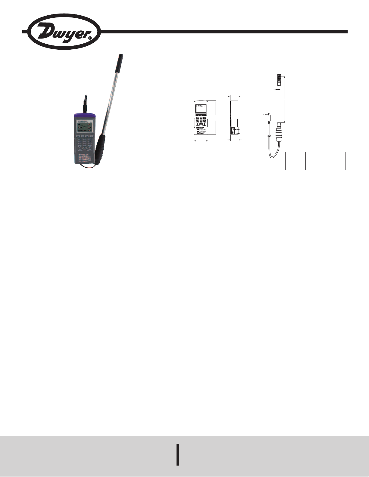
Model VT-300 Miniature Vane Thermo-Anemometer
9V DC
POWER PORT
1/8˝ RS232
PORT
3
/4
[
19.05]
5
1/64
[
20.13]
P
S/2
P
LUG
TELESCOPING
1
-23/64
[
34.73]
3
-21/64
[
84.53]
Specifications - Installation and Operating Instructions
etracted
R
xtended
E
Bulletin TE-VT-300
“L”
1-27/32˝ (301 mm)
1
8-1/4˝ (946 mm)
1
The Model VT-300 Miniature Vane Thermo-Anemometer measures air velocity,
ir volume, temperature, and humidity inside air ducts. This meter includes a
a
elescoping vane probe that is only 0.7˝ (18 mm) in diameter that allow s duct
t
traverse measurements up to 20˝ ducts. User-selectable units include ft/min, m/s,
knots, mph, and km/hr. The vane probe has a built-in sensor to record temperature
in °F or °C, as well as humidity in %RH. There are three modes which include
viewing data in real time, manual recording, and automatic recording. Model VT-300
can store measurements that can later be transferred to a PC via RS-232
communication. The vane probe is detachable for easy replacement, if necessary,
or as an addition to Model 9671. Each unit is supplied with a hard carrying case,
batteries, logging software CD, USB to RS-232 cable and instruction manual.
BATTERY INSTALLATION
Model VT-300 requires (4) AAA batteries for use. To install or replace batteries,
open the back compartment and remove the current batteries, if applicable. Insert
new batteries, being aware of correct polarity.
The battery icon will appear on the LCD when the power is low and the batteries
will need to be replaced.
METER SETTING
Before measuring, check the meter setting to confirm that the basic settings of the
meter are what is needed (change them if necessary). To enter the settings
function from the welcome screen, press F4 (SET).
To change settings:
1. Press the arrow buttons to shift between the variable settings.
2. Press F2 (EDIT) to enter modification mode. If the setting changes using
numbers, press the corresponding number on the keypad.
3. Press F4 (NEXT or BACK) to enter the next or previous page.
4. Press F1 (EXIT) to return to the main menu.
DWYER INSTRUMENTS, INC.
P.O. BOX 373 • MICHIGAN CITY, INDIANA 46360, U.S.A. Fax: 219/872-9057 e-mail: info@dwyermail.com
SPECIFICATIONS
AIR VELOCITY
Range: 98.4 to 3937 ft/min (0.5 to 20 m/s).
Accuracy: ±3% of reading + 0.2 m/s.
Resolution: 0.1 m/s.
Response Time: 1 s.
TEMPERATURE
Range: -4 to 140°F (-20 to 60°C).
Accuracy: ±1°F (±0.6°C) from -4 to 122°F (-20 to 50°C); ±2.2°F (±1.2°C) from
122 to 140°F (50 to 60°C).
Resolution: 0.1°F (0.1°C).
Response Time: 60 s (typ).
RELATIVE HUMIDITY
Range: 0.1 to 99.9% RH.
Accuracy: ±3% RH at 25°C (10 to 90% RH); ±5% RH (0.1 to 10% RH, 90 to
99.9% RH).
Resolution: 0.1% RH.
Response Time: 60 s (typ).
AIR VOLUME
Range: 0 to 99,999 (CFM or m
Resolution: 0.1 (0 to 9999.9) or 1 (10,000 to 99,999).
WET BULB
Range: -7.6 to 158°F (-22 to 70°C).
Resolution: 0.1°F (0.1°C).
METER
Temperature Limits:
Operating: 32 to 122°F (0 to 50°C);
Storage: -4 to 122°F (-20 to 50°C).
Humidity Limits:
Operating: <80% RH;
Storage: <90% RH.
Display: 1 x 1.8˝ (26 x 45 mm).
Serial Communications: 9600 bps, 8 data bits, no parity.
Power Requirements: (4) AAA 1.5 V alkaline batteries, included, user
replaceable.
Battery Life: 100 hours.
Vane Diameter: 0.7˝ (18 mm).
Weight: 7.41 oz (210 g).
3
/s).
Phone: 219/879-8000 www.dwyer-inst.com
Page 2
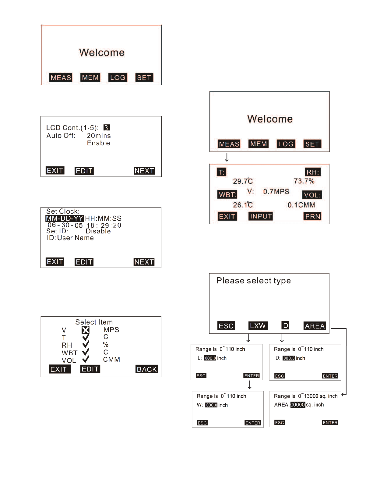
On the display menu, the variable settings are:
LCD Brightness: 5=brightest
•
Auto Off Function: selectable from 1 to 20 min; Auto Off is also enabled/disabled
•
rom this screen.
f
n the settings menu, the variable settings are:
O
• Date/Time Format: Choose MM-DD-YY, DD-MM-YY, or YY-MM-DD and set the date
and time.
• ID: Enable/disable the use of an ID and set the ID.
PERATION
O
here are three measurement modes:
T
. Single Measurement (MEAS)
1
2. Manual Logging (MEM)
3. Automatic Logging (LOG)
ingle Measurement
S
he single measurement setting allows for measurement without recording any
T
emory. To get to this setting:
m
. Turn on the meter.
1
2. Press F1 (MEAS).
3. Hold the vane probe in the area being measured.
On the logging menu, the user can choose which items the meter will record and
which unit will be used. The available units are:
• Air Velocity (V): MPH, MPS, FPM, KNT, KMH
• Temperature (T): °C, °F
• Relative Humidity (RH): %
• Wet Bulb Temp (WBT): °C, °F
• Air Volume (VOL): CFM, CMM
In this setting, it is also possible to calculate air volume. To do this from the single
measurement screen, press F2 (INPUT). This screen gives three options of how to
input the area.
1. For a rectangular area, press F2 (LXW) and input the length and width of the area.
2. For a circular area, press F3 (D) and input the diameter of the area.
3. If the exact area is known or can be approximated, press F4 (AREA) and input the
area manually.
Page 3

anual Logging
M
he manual logging setting allows for the user to manually record up to 99 data
T
oints. To get to this setting:
p
. Turn on the meter.
1
2. Press F2 (MEM).
3. Press F2 (MEAS) to measure the data.
4. Press F4 (SAVE) to save the measurement or F1 (ABORT) to exit the
easurement.
m
. To edit the file name of the recorded value, press F3 (EDIT). Press the number
5
eys until the required character is highlighted, then press the next key and
k
epeat until the file name is complete.
r
6. To view other recorded values, press the arrow keys to move between
measurements.
o delete data measurements:
T
. Press F2 (CLR) briefly to delete one data point, or press and hold F2 (CLR) to
1
elete all data points.
d
. Press F2 (YES) to confirm deletion.
2
utomatic Logging
A
he automatic logging setting allows for the meter to automatically record based on
T
the user’s pre-set functions. These functions include start and stop time and date,
and sample rate. This setting allows memory for 2400 points.
To change logging settings:
1. Press F3 (LOG).
2. Press F3 (SET).
3. Use the arrow keys to move between the settings and find the setting needed to
be changed.
4. Press F2 (EDIT).
5. Use the number keys to change the values and press F4 (ENTER) to change
between sections of one setting.
6. When done, press F4 (ENTER).
Page 4

o start logging after the logger has been set up:
T
. From home screen, press F3 (LOG).
1
. Press F2 (START).
2
. While logging, press F2 (MEAS) to see what the measurements are in real time,
3
or press F4 (VIEW) to see the specific data points.
4. To stop logging, press F1 (STOP).
o see the recorded data points, press F4 (NEXT). Then press F1 (P-PG) to review
T
he previous 100 points or F2 (N-PG) to review the next 100 points. Use the arrows
t
o view each point individually.
t
Page 5

OFTWARE
S
he included software is a quick tool for downloading recorded data to a PC for
T
urther analysis. The software requires Windows
f
®
8/2000/NT/XP or newer.
9
To download software, insert the included CD into the PC’s CD drive. When
prompted, run the “autorun.exe” program. Click on the “Install Software” button and
follow the on-screen instructions to complete software installation. While on the
ain menu of the CD, connect the meter to the computer using the supplied USB
m
o RS232 cable. Click on the “Install USB Driver” button, then on the next screen,
t
lick on the button for the operating software being used. Follow the on-screen
c
nstructions to complete USB driver installation.
i
In the software, there are 4 drop-down menus at the top of the page:
File
New: To create a new file.
oad: To open a saved file.
L
ave: To save the current file.
S
ave As: To save the current file as a new file name.
S
Print: To print logging data, memory data, or both.
Exit: To exit the software.
Mode
Memory: This displays recorded data from the manual logging setting.
Logger: This displays the recorded data from the automatic logging setting. 100
data points can be viewed at one time. Use the drop down bar in the top center of
the screen to change between ranges.
ROUBLESHOOTING
T
f any problems occur while using Model VT-300, refer to the below table to find
I
ossible solutions.
p
Problem
Solution
Make sure to hold the power button
or more than 200 ms.
f
he meter has been
T
owered on, but the
p
isplay is not shown.
d
heck that the batteries are placed at
C
he correct polarity and have good
t
ontact.
c
Remove the batteries for 10 seconds
and then replace.
Replace old batteries with a new set.
heck whether the low battery
C
ndicator is displayed before the
he display
T
isappears.
d
i
isplay disappears. If so, replace the
d
atteries.
b
If an error message appears on the display, refer to the below table to see what
each error message means.
Error Code
2
E
3
E
4
E
Problem
he meter value is under the recordable range.
T
he meter value is above the recordable range.
T
calculated source value has occurred.
A
MAINTENANCE/REPAIR
Upon final installation of the Model VT-300 Miniature Vane Thermo-Anemometer,
no routine maintenance is required. The Model VT-300 is not field serviceable and
s not possible to repair the unit. Field repair should not be attempted and may void
i
arranty.
w
WARRANTY/RETURN
Refer to “Terms and Conditions of Sale” in our catalog and on our website. Contact
customer service to receive a Return Goods Authorization number before shipping
the product back for repair. Be sure to include a brief description of the problem
plus any additional application notes.
Users can also use the drop down bar near the top right to change between reading
the memory and logger modes.
Port
Select the correct Com port to ensure the meter is communicating correctly with the
PC. For most PCs, the Com port number is Com 1, but there are 8 Com ports for
selection in the software. While the meter is connected to the PC, “PC Mode” will
appear on the LCD of the meter and “Com #” and “Edit” will show in the bottom left
corner of the software screen.
Command
Download Memory Data: Download the measured logging data (from manual
logging setting) from the meter to the PC.
Download Logger Data: Download the measured memory data (from automatic
logging setting) from the meter to the PC.
Download All Data: Download the measured memory and logging data from the
meter to the PC.
Upload Memory Description: Upload pre-edited file names from the PC to the
meter.
To edit the file names, double-click the mouse over the name needing to be
changed, then the cursor will flash to indicate that the column is ready for editing.
NOTICE
Before uploading or downloading, make sure to choose the
correct download mode. If “Download Memory Data” is chosen,
but “Download Logger Data” is executed, the mode will need to be switched to have
the correct display.
Page 6

©Copyright 2014 Dwyer Instruments, Inc. Printed in U.S.A. 12/14 FR# 444220-00
DWYER INSTRUMENTS, INC.
P.O. BOX 373 • MICHIGAN CITY, INDIANA 46360, U.S.A. Fax: 219/872-9057 e-mail: info@dwyermail.com
Phone: 219/879-8000 www.dwyer-inst.com
 Loading...