

Page 1
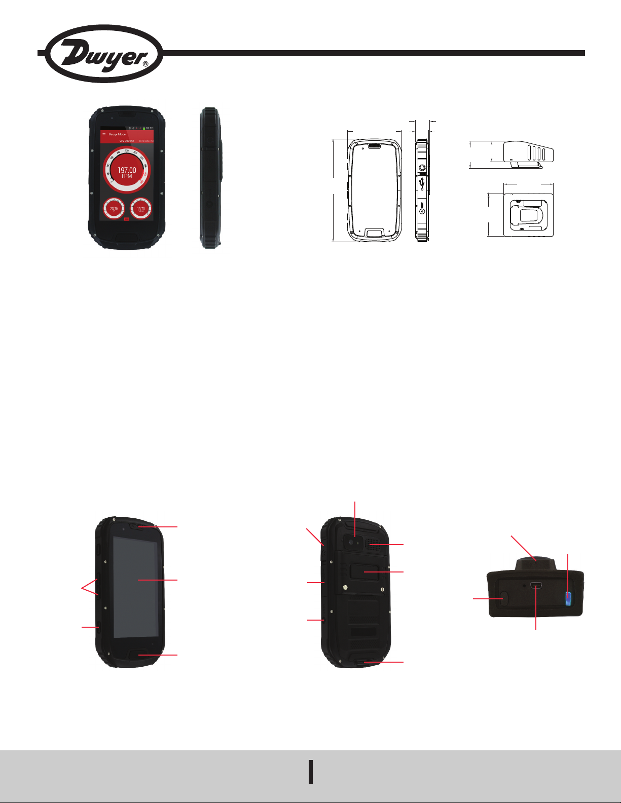
Model UHH2 Universal Handheld Test Instrument
3
-1/16 [77.79]
1
3/16
[
20.64]
3/4
[19.05]
5
-13/16
[
147.64]
1
-35/64
[
39.29]
2
-13/32
[
61.12]
1-3/16
[30.16]
2
-13/16
[
71.44]
Specifications - Installation and Operating Instructions
Bulletin TE-UHH2
The Model UHH2 Universal Handheld Test Instrument provides the functionality
and versatility of the Mobile Meter
handheld. Wireless anemometer, hygrometer, and pressure probes communicate to
he handheld using Bluetooth SIG, Inc. wireless technology and can all be displayed
t
imultaneously. Each UHH2 includes a UHH2 handheld base unit, UHH-BTG
s
wireless mobile gateway, two USB charging cables, charging block, mini-screwdriver,
ser manual, and headphones.
u
EATURES/BENEFITS
F
• Rugged weatherproof housing withstands 1.5 meter drop test
• Wireless measurement of pressure, air velocity, air flow, temperature, and humidity
• Share logged data directly from handheld over Wi-Fi, GSM or CDMA networks
APPLICATIONS
• Building commissioning
• Building balancing
• Testing HVAC equipment performance
FEATURE OUTLINE
Volume
buttons
Power/sleep
button
®
Software App on a rugged IP68 Android®based
Headphone
connection with
integral protective
USB connection for
data transfer or
recharging with
integral protective
Speaker
Backlit
touchscreen
LCD
Home
button
rubber cap
rubber cap
Reset
button
Display: 4.3˝ QHD Gorrilla glass touch screen, 960x540.
Wireless Distance: 50´ (15 m) or greater.
Response Time: 1 s.
emperature Limits: Operating: -4 to 140°F (-20 to 60°C); Storage: -40 to 176°F
T
-40 to 80°C).
(
Humidity Limits: 5 to 95% RH.
ower Requirements: 2000 mAh lithium ion battery, installed functional, non-
P
eplaceable.
r
emory: RAM 1G & ROM 4G.
M
Operating System: Android 4.2.2.
CPU: MTK6589W Quad Core 1.2 GHz.
Enclosure Rating: IP68.
Weight: 15.9 oz (450 g).
Agency Approvals: CE, FCC compliant.
Camera
Speaker
SIM card
access
Hand strap
clip
Figure 1
Power
button
Belt clip
USB charger
Bi-color
LED
connector
DWYER INSTRUMENTS, INC.
P.O. BOX 373 • MICHIGAN CITY, INDIANA 46360, U.S.A.
Phone: 219/879-8000
Fax: 219/872-9057
www.dwyer-inst.com
e-mail: info@dwyermail.com
Page 2
OPERATION
owering On/Off
P
o turn on the unit, press and hold the power button. Wait approximately 15 seconds
T
or it to fully power on. Swipe to unlock the unit.
f
To turn off the unit, either press and hold the power/sleep button and press Power
Off when prompted on the LCD or press the reset button.
attery
B
he Model UHH2 utilizes an internal rechargeable battery. The battery symbol in the
T
op right of the screen shows the status of the battery.
t
OTICE
N
harge the unit to full battery before using.
c
hen the battery is low, the battery symbol will turn red. When this occurs, use the
W
hen the UHH2 is received, it will only have a partial charge.
W
se the included USB charging cable and charging block to
U
included USB charging cable and charging block to charge the unit.
Mobile Meter
he Dwyer Mobile Meter
T
n the icon to open the app.
o
Note: When the app is opened, an error message will pop up. This can be bypassed
(
y pressing OK, and can be permanently stopped by adding a Google Play
b
®
App Operation
®
pp is located in the top left of the unit’s main screen. Click
a
®
ccount
a
in the device’s settings menu.)
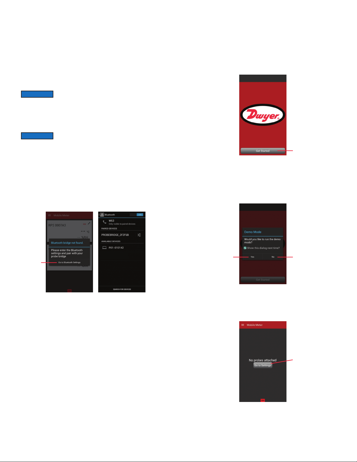
Upon opening the Mobile Meter
ateway is paired to the device.
G
®
app, you will see “Get Started” if the Wireless Mobile
NOTICE
The UHH2 comes factory paired to the included UHH-BTG
Wireless Mobile Gateway. Before pairing a new wireless
gateway, the current one should be unpaired.
Pairing to the Mobile Gateway
In order to pair the Model UHH2 to the Model UHH-BTG Wireless Mobile Gateway,
first turn on the gateway by pushing the power button (See Figure 1). Next, either
pen the Mobile Meter
o
n the device. The bridge is automatically discoverable once it is turned on. Select
o
he device named PROBEBRIDGE followed by the serial number of your gateway.
t
®
pp or go directly to the Bluetooth menu in the settings menu
a
If prompted for a pass code, type in 0000. Once the gateway is paired to the UHH2,
the blue LED on the gateway will flash when communications are transmitted
between the UHH2 and UHH-BTG.
Touch to
go to
Bluetooth
menu
Figure 2
Pairing Probes or Modules to Gateway
The wireless probes and modules automatically become discoverable to the gateway
when they are turned on if they are not already connected to another gateway or
Model UHH/UHH2 base unit. You must be in the Mobile Meter
®
or other Dwyer
Instruments, Inc. approved app to see which probes are paired. The blue LED on
the gateway and the green LED on the probe will flash rapidly when there is
communication between the probe and the gateway.
Touch to get started
igure 3
F
he app also has a demo mode which can be selected at this time, which allows
T
sers to familiarize themselves with the app and its functions before connecting their
u
wn instruments. To leave demo mode and enter measurement mode, press the
o
back button until the main screen is up, then press Get Started and press No on the
box that pops up.
Touch to enter
demo mode
Touch to enter
measurement mode
Figure 4
During the first time using the app, no probes will be paired yet. It will prompt to go
to the probe set up menu to find available probes. If they aren’t already, turn on the
probes or modules at this time to make them discoverable.
Figure 5
Touch to
set up probes
Page 3

The probe list automatically refreshes to show any new probes. Select the desired
robes or modules by touching the box on the right side of the screen. The probe
p
election screen can always be accessed by pressing the three lines in the top
s
eft of the Mobile Meter
l
odules will be stored in this list as well. Probes or modules that are currently
m
®
pp and going to “Setup”. The past paired probes and
a
unavailable will be in grey, but they can still be selected to display when they become
active.
o delete or rename a probe in this screen, simply press and hold the probe and
T
lick on the desired option.
c
ressing the arrow next to “Setup” in the top left of the screen will return to the active
P
probes list.
Any of the probes can be made full screen by touching the desired probe. In the full
creen view, users can scroll through the active probes by swiping the screen to the
s
eft or right.
l
Touch to go back to
previous menu
ress and hold to
P
Touch to select
probe
delete or rename probe
Figure 6
NOTICE
his active probe list will give the probe names and the measurement data for all of
T
t is recommended that only four probes be selected due to the
I
andwidth limitations between the UHH2 and the gateway.
b
the selected probes. Additional information such as low battery warnings of the
probes and the communication status is available on the screen.
Probe name
Connection status:
Green — connected
Probe type
Red — not connected
igure 8
F
he measurements are normally displayed as a digital meter. If desired, the
T
easurements can be shown as an analog gauge or as a graph by touching the
m
three lines in the top left and choosing the desired option. Preferences and
parameters can also be adjusted in this menu.
Touch to
access
arameters
p
Figure 9
Figure 7
Page 4

In the Preference Menu, users can select which parameter will be displayed larger
n the screen by checking the box next to Priority. Also, the user can select the
o
unction of the parameter, engineering units, and logging method. The name of the
f
robe can be changed and calibration data (if available) will be displayed. Pressing
p
he arrow in the top left will return to the active probe list.
t
ouch to make
T
arameter priority
p
Touch to
change units
ouch to change
T
ogging method
l
igure 10
F
Logging can be initiated in any of the above views by either pressing the button on
the probe or by pulling up on the red square on the bottom and pressing Log. If the
logging is set to duration, which can be set in the Preferences menu, it will log
continuously for the set duration.
In order to end a log file, press the Save Log button on the bottom of the screen.
he log can then be either viewed, shared, or closed. In order to view the log file,
T
ouch Open Log. To share the log file, select to share the file via wireless
t
ommunication to another device, email the file directly from the phone, or share it
c
ia Wi-Fi to another device on the same network. Otherwise, touching OK will close
v
the file for later access.
Figure 12
FCC RF EXPOSURE INFORMATION AND STATEMENT
The SAR limit of USA (FCC) is 1.6 W/kg averaged over one gram of tissue. Device
types: S09 (FCC ID: ZHN-W63) has also been tested against this SAR limit. The
ighest SAR value reported under this standard during product certification for use
h
t the ear is 0.430 W/kg and when properly worn on the body is 0.772 W/kg. This
a
evice was tested for typical body-worn operations with the back of the handset kept
d
1.5 cm from the body. To maintain compliance with FCC RF exposure requirements,
use accessories that maintain a 1.5 cm separation distance between the user’s body
and the back of the handset. The use of belt clips, holsters, and similar accessories
should not contain metallic components in its assembly. The use of accessories that
o not satisfy these requirements may not comply with FCC RF exposure
d
equirements and should be avoided.
r
Touch to start log
Figure 11
Touch to end and
save log file
This device complies with part 15 of the FCC rules. Operation is subject to the
following two conditions: (1) This device may not cause harmful interference, and (2)
This device must accept any interface received, including interference that may
cause undesired operation.
NOTE: The manufacturer is not responsible for any radio or TV interference caused
by unauthorized modification to this equipment. Such modifications could void the
user’s authority to operate the equipment.
This equipment has been tested and found to comply with the limits for a Class B
digital device, pursuant to part 15 of the FCC Rules. These limits are designed to
provide reasonable protection against harmful interference in a residential
installation. This equipment generates, uses, and can radiate radio frequency energy
and, if not installed and used in accordance with instructions, may cause harmful
interference to radio communications. However, there is no guarantee that
interference will not occur in a particular installation. If this equipment does cause
harmful interference to radio or television reception, which can be determined by
turning the equipment off and on, the user is encouraged to try and correct the
interference by one of more of the following measures:
• Reorient or relocate the receiving antenna
• Increase the separation between the equipment and receiver
• Connect the equipment into an outlet on a circuit different from that to which the
receiver is connected
• Consult the dealer or an experienced radio/TV technician for help
MAINTENANCE/REPAIR
Upon final installation of the Model UHH2, no routine maintenance is required. The
Model UHH2 is not field serviceable and should be returned if repair is needed. Field
repair should not be attempted and may void warranty.
WARRANTY/RETURN
Refer to “Terms and Conditions of Sale” in our catalog and on our website. Contact
customer service to receive a Return Goods Authorization Number before shipping
the product back for repair. Be sure to include a brief description of the problem plus
any additional application notes.
©Copyright 2015 Dwyer Instruments, Inc.
DWYER INSTRUMENTS, INC.
P.O. BOX 373 • MICHIGAN CITY, INDIANA 46360, U.S.A.
Android®is a registered trademark of Google Inc.
Printed in U.S.A. 6/15 FR# 444317-00 Rev. 1
Phone: 219/879-8000
Fax: 219/872-9057
www.dwyer-inst.com
e-mail: info@dwyermail.com
 Loading...