

Dwyer Instruments TUF-320 series, TUF-200 series, TUF-400 series, TUF-500 series, TUF-650 series Specifications-installation And Operating Instructions
...Page 1
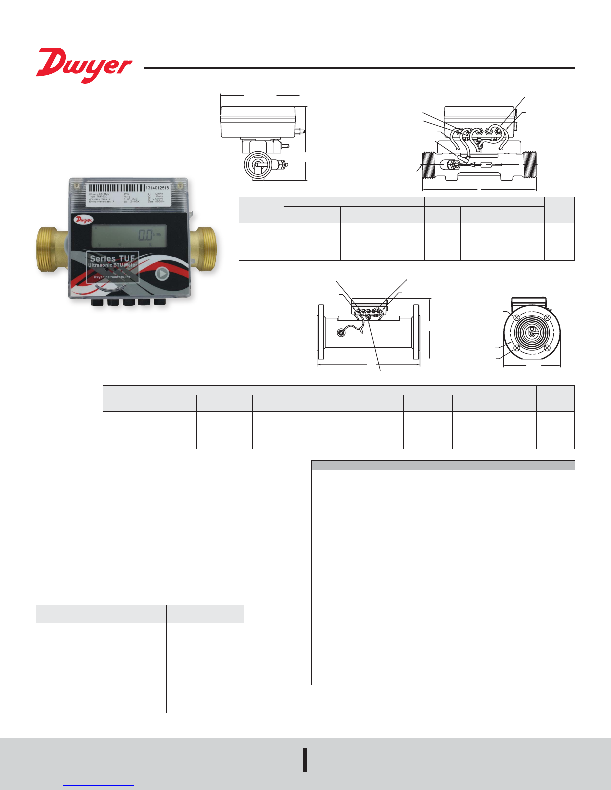
Series TUF Ultrasonic Energy Meter
4´ RETURN PIPE TEMP SENSOR
4-1/4
T
®
Specications - Installation and Operating Instructions
[108.00]
4´ FLOW PIPE TEMP SENSOR
4´ RETURN PIPE TEMP SENSOR
4´ 4-CORE WIRE
[2 COMMUNICATION, 2 POWER]
H
2X D
THREAD
Model
TUF-150-XX
TUF-200-XX
TUF-250-XX
TUF-320-XX
TUF-400-XX
Dimensions in [mm] Flow Rate GPM [LPM]
4-21/64 [110.00]
5-1/8 [130.00]
6-19/64 [160.00]
7-3/32 [180.00]
7-7/8 [200.00]
G3/4B
G1B
G11/4B
G11/2B
G2B
3-31/32 [101.00]
3-31/32 [101.00]
4-11/64 [106.00]
4-29/64 [113.00]
4-49/64 [121.00]
Max Flow
(Qs)
13 [50]
22 [83]
31 [117]
53 [200]
88 [333]
DNXX
L
Nominal Flow
Range (Qp)
6.6 [25]
11 [42]
15 [58]
26 [100]
44 [167]
Bulletin F-TUF
2.8´ WATER-IN
FLOW SENSOR
2.8´ WATER-OU
FLOW SENSOR
Min Flow
(Qi)
0.1 [0.5]
0.2 [0.8]
0.3 [1.2]
0.5 [2]
0.9 [3.3]
Weight
lb [kg]L D H
3.1 [1.4]
3.1 [1.4]
4.1 [1.8]
5.2 [2.3]
6.6 [3.0]
4´ FLOW PIPE TEMP SENSOR
[2 COMMUNICATION, 2 POWER]
Dimensions in [mm] Flow Rate GPM [LPM]
Model
TUF-500-XX
TUF-650-XX
TUF-800-XX
TUF-1000-XX
TUF-1250-XX
The Series TUF Tennant Ultrasonic BTU Flowmeter is a MID/EN1434 approved
highly accurate and stable energy meter. It utilizes ultrasonic technology to measure
heating and cooling energy consumption. The Series TUF incorporates a owmeter,
temperature meter, and a calculator into a single, compact unit. The size and lack of
moving parts means the Series TUF requires minimal maintenance. The 8-digit LED
display enables easy reading of the meter’s recorded values; including temperature,
ow-rate, energy consumption, etc. These features make it ideal for installation on
chillers, boilers, and individual apartment piping. With the optional couplings it is
capable of being used with either NPT or BSPT pipe sizes. It is the perfect meter for
tenant billing applications.
FEATURES
• Lower maintenance costs with local parameter display and no moving parts
• Serial communication output allows for easy transfer of data
• Flow and temperature monitor in one unit eliminates the need for multiple units
Model
TUF-150-XX
TUF-200-XX
TUF-250-XX
TUF-320-XX
TUF-400-XX
TUF-500-XX
TUF-650-XX
TUF-800-XX
TUF-1000-XX
TUF-1250-XX
Process
Connection
G-3/4
G1
G1-1/4
G1-1/2
G2
GB9119 Flange
GB9119 Flange
GB9119 Flange
GB9119 Flange
GB9119 Flange
7-7/8 [200]
7-7/8 [200]
8-55/64 [225]
9-27/32 [250]
9-27/32 [250]
Corresponding
Pipe Fitting
1/2˝ NPT or BSPT
3/4˝ NPT or BSPT
1˝ NPT or BSPT
1-1/4˝ NPT or BSPT
1-1/2˝ NPT or BSPT
2˝ DN 50 PN 16 Flange
2-1/2˝ DN 65 Flange
3˝ DN 80 Flange
4˝ DN 100 Flange
5˝ DN 125 Flange
6-1/2 [165.00]
7-9/32 [185.00]
7-7/8 [200.00]
8-21/32 [220.00]
9-27/32 [250.00]
9-27/32 [250]
10-7/16 [265]
11-1/32 [280]
12-13/64 [310]
12-63/64 [330]
2.8´ WATER-IN FLOW SENSOR
4´ 4-CORE WIRE
L
4-59/64 [125.00]
5-45/64 [145.00]
6-19/64 [160.00]
7-3/32 [180.00]
8-17/64 [210.00]
SPECIFICATIONS
Service: Clean, compatible liquids.
Wetted Materials: Brass and 316L SS.
Range: See chart.
Display: 8-digit LED.
Accuracy: BTU: EN1434/CJ128 Class 2; Flow: ±(2+(0.02 Qp / Q))%; Temperature:
0.18°F (±0.1°C).
Power Requirements: 24 VDC or 3.6 V ER26500 lithium metal battery, user
supplied and installed, battery acts as back-up if power is lost.
Power Consumption: 1 W.
Temperature Limits: Ambient: 41 to 131°F (5 to 55°C); Process: 36 to 203°F (2 to
95°C).
Humidity Limit: <93%.
Pressure Limits: 232 psi (16 bar) for DN15 to DN40; 362 psi (25 bar) for >DN50.
Pressure Drop: <1.5 psi (10 kPa).
Process Connection: See chart.
Serial Communications: Modbus
Enclosure Rating: IP65.
Enclosure Material: Plastic.
Repeatability: Flowmeter: 1%.
Electrical Connections: 3 ft (0.91 m) 4x0.2 mm2 cable with terminal block.
Flow Direction: Unidirectional.
Mounting Orientation: Horizontal or vertical.
Weight: See chart.
Agency Approvals: CE.
45/64 [18.00]
45/64 [18.00]
45/64 [18.00]
45/64 [18.00]
45/64 [18.00]
2.8´ WATER-OUT FLOW SENSOR
´N´ NO. OF HOLES
[SEE TABLE]
H
ØD1 B.C.
ØD2
Max Flow
(Qs)
4
132 [500]
4
220 [833]
8
352 [1333]
8
528 [2000]
8
881 [3333]
®
RTU or BACnet MSTP (selectable)**.
Nominal Flow
Range (Qp)
66 [250]
110 [417]
176 [667]
264 [1000]
440 [1667]
Min Flow
(Qi)
0.7 [2.5]
1.1 [4.2]
1.8 [6.7]
2.6 [10]
4.4 [17]
ØD
Weight
lb [kg]L ØD H ØD1 ØD2 N
30.8 [14]
30.2 [13.7]
37.5 [17]
41.8 [19]
57.3 [26]
DWYER INSTRUMENTS, INC.
P.O. BOX 373 • MICHIGAN CITY, INDIANA 46360, U.S.A.
Phone: 219/879-8000
Fax: 219/872-9057
www.dwyer-inst.com
e-mail: info@dwyermail.com
Page 2
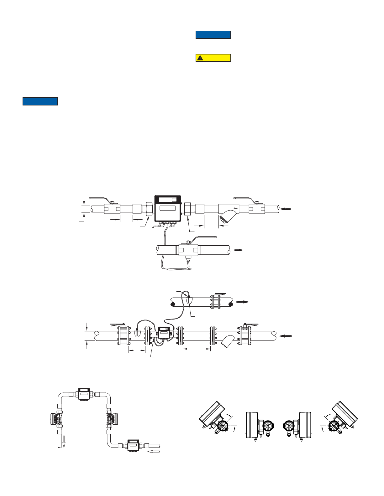
INSTALLATION INSTRUCTIONS
BALL
BALL
D
TEMPERATURE SENSOR
1. Install the meter as shown in either Figure 1 or Figure 2.
2. Mount the temperature sensor with the blue tag on the corresponding return pipe on
application. The sensor with the red tag has already been installed in the meter.
3. Flush the system in the proper direction until:
• No impurities remain in the lter and pipe.
• No water leaks when pressure is added to the system.
• The humidity inside the enclosure containing the meter does not exceed 93%.
4. After ushing for a period of time; close the ball valves on either side of the meter
and ush the impurities out of all lters.
*3.6 V ER26500 battery may be purchased separately to power display only.
INSTALLATION REQUIREMENTS
NOTICE
measuring accuracy.
1. Ensure that there is a 10 diameter straight run of pipe upstream and a 5 diameter
straight run of pipe downstream form the meter.
2. See the installation positions in Figure 3, in which A and B are the proper installation
positions, while C and D are the improper positions.
3. If the meter is installed on the horizontal pipe, it must be oriented at least 45° from
horizontal (see Figure 4). If the meter’s face is horizontal, then debris accumulation
can increase inaccuracies (see gure 5 for correct and incorrect orientations). There
is no special requirement when installing on the vertical pipe work.
4. Handle display with care. LCD display may damage with force.
Note: the meter can be installed on the return pipe or the supply pipe according to
user’s needs, but it should be selected in advance.
If the following requirements are not followed, then large air
particles and impurities in the pipe could inuence the meter’s
INSTALLATION NOTES
NOTICE
CAUTION
optional battery could cause the battery to explode and cause injury to people and
damage the meter.
1. Avoid tugging on the temperature probe’s cables.
2. Ensure the water is owing in the direction indicated by the arrow on the meter’s
body.
3. If several meters are installed on the same vertical pipe work, each meter should be
separated from the others to avoid pipe leakage or fallen debris that could affect the
other meters’ operation.
Do not directly weld the meter on to the pipe; the extreme heat
will damage the BTU meter’s internal elements.
Do not install the meter near a high temperature heat source
such as during electro gas welding. Doing so after installing an
STRAIGHT
JOINT
FILTER
PIPEPIPEPIPE PIPE PIPE
10D
UNION NUT
WATER RETURN
BALL
VALVE
BUTTERFLY
VALVE
RETURN WATER
TEMPERATURE
SENSOR
10D
BUTTERFLY
FILTER
VALVE
WATER SUPPLY
WATER RETURN
VALVE
WATER SUPPLY
STRAIGHT
VALVE
PIPE PIPE
D
5D
UNION NUT
BUTTERFLY
VALVE
JOINT
Figure 1: Installation Diagram for TUF-150/400
SENSOR
SLEEVE
5D
SUPPLY WATER
Figure 2: Installation Diagram for TUF-500/2000
Figure 3: Installation Positions
45° MIN.
45° MIN.
Figure 4: Mounting Rotation
Page 3

Yellow A+ (BACnet or Modbus)
Green B- (BACnet or Modbus)
Black- (24VDC or 24VAC)
Red+ (24VDC or 24VAC)
Temp Sensor In
Temp Sensor Out
Flow Sensor Out
Flow Sensor In
1. If meter is not in use during freezing conditions, drain all water from the connecting
pipe. Low temperatures will cause the water to freeze in the pipe and damage the
meter.
2. This device is intended to be used with clean water. While dirty water will not
damage the meter, it will cause errors in the reading.
3. A lter should be mounted near the meter and cleaned regularly.
4. If the heat exchanging system is operating normally, but the instantaneous ow-rate
of the heat meter reduces signicantly, then there is too much dirt in the lter. This
will narrow the pipe and reduce the ow. Cleaning the lter will x the problem.
5. To protect the meter and avoid damage from harsh conditions, it is recommended
that the meter be encased in an enclosure.
6. Primary Address: rst 2 digits of Manufacturer ID
7. Secondary Address: later 8 digits of Manufacturer ID
8. Company Code: BAS (08 33)
• Version: 54
DISPLAY
1. Switching Between Information
Holding down the button for > 1s will switch the sections from curren information ▲,
to monthly information ▲▲, and then to other information ▲▲▲. Once in the
desired section, pressing the key will switch the information shown for the given
section.
2. Display Units
Energy is displayed in kW•h, power is displayed in kW, ow volume is displayed as
3
, and ow-rate is displayed in m3/h.
m
3. Display Details
a. “Monthly Reading Date” is displayed as “Pd= XX”, in which XX is the end date of
the current month’s energy summation. The factory default value is 31, meaning
that the monthly recording period ends at midnight on the 31st day of the month. At
this time the current month’s cumulated energy will be stored and the system will
begin to record the next month’s energy.
b. The meter can store and display the recordings from the past 18 months.
c. The units for “Sum of Working Time” (hours) is displayed as h.
d. “Software and Protocol Editions” are displayed as “UEr.X.X X.X”. The rst X.X is
the software edition code and the second X.X is the communication protocol edition
code.
e. “Leaving-factory serial number” is the meter’s identication number, which is the
same as the one in the external label. This serial number is a unique number set by
the factory; it is also the secondary address in M-BUS system.
f. Battery Voltage displays “UCC=X.XX” (the default unit is Volts). When the battery’s
voltage capacity is lower than 2.9±0.1 V, “ ” will appear on the display. This
symbol will not appear if no battery is installed.
g. If there are any unresolved errors, the start date will display as normal but the end
date will display “00-00-00”, and then the error message will be displayed.
4. LCD Display Data:
• Cooling energy
• Heat energy
• Volume
• Operating time
• Flow temperature
• Return temperature
• Temperature difference
• Power
• Volume ow
• Recorded date
• Recorded energy
• Recorded volume
Error Message Table
Error
Messages Explanation
IN—CLOSE
IN—OPEN
OU—CLOSE
OU—OPEN
FL-OPEN
Temperature sensor of water supply is in closed state
Temperature sensor of water supply is in open state
Temperature sensor of return water is in closed state
Temperature sensor of return water is in open state
Flow sensor failure. (Could be caused by air in the meter, the
absence of water, or water owing in the wrong direction)
COD=XXXX
There is an error in malfunction record. “XXXX” is the error code
Low Battery*
*Battery Not Included
Page 4

4. Display Menus
Press button
Press button
Press button
Press button
Press button
Press button
Press button
Current Information Monthly Information Other Information
Hold button
Sum of cooling
energy
Sum of heating
energy
Power
Sum of flow rate
Flow velocity
Forward temperature
Return temperature
Temperature
difference
Press button
Press button
Press button
Press button
Press button
Press button
Monthly reading
date
Current date
Sum of monthly
energy
History reading
date 1
History reading
energy 1
Sum of flow rate 1
History reading
date 2
History reading
energy 2
Press button
Press button
Press button
Press button
Press button
Press button
Press button
Press button
Hold button
Current: Year,
month, date
Current: Hour,
minute, second
Sum of current
working time
LCD segment test
Protocol version
Primary address
Secondary address
Sum of flow rate 2
-History reading date 2
-History reading energy 2
-Sum of flow rate 2
Press button
-Error 4 message
-Error 4 beginning time
-Error 4 ending time
Battery voltage
Error 1 message
Error 1 beginning
time
Error 1 ending time
Press button
Press button
Press button
Press button
WARRANTY/RETURN
Refer to “Terms and Conditions of Sale” in our catalog and on our website. Contact
customer service to receive a Return Goods Authorization number before shipping the
product back for repair. Be sure to include a brief description of the problem plus any
additional application notes.
©Copyright 2018 Dwyer Instruments, Inc. Printed in U.S.A. 9/18 FR# 444246-50 Rev. 3
DWYER INSTRUMENTS, INC.
P.O. BOX 373 • MICHIGAN CITY, INDIANA 46360, U.S.A.
Phone: 219/879-8000
Fax: 219/872-9057
www.dwyer-inst.com
e-mail: info@dwyermail.com
 Loading...