

Page 1
Bulletin T-TSW-1-RB
2-19/32
[
65.53]
3
-5/8
[92.08]
6
-21/32
[
168.91]
PROBE
INPUTS
2 37 8 9 10 11
OUTPUTS
Sd1
TS2-K
OUT 1
POWER
SUPPLY
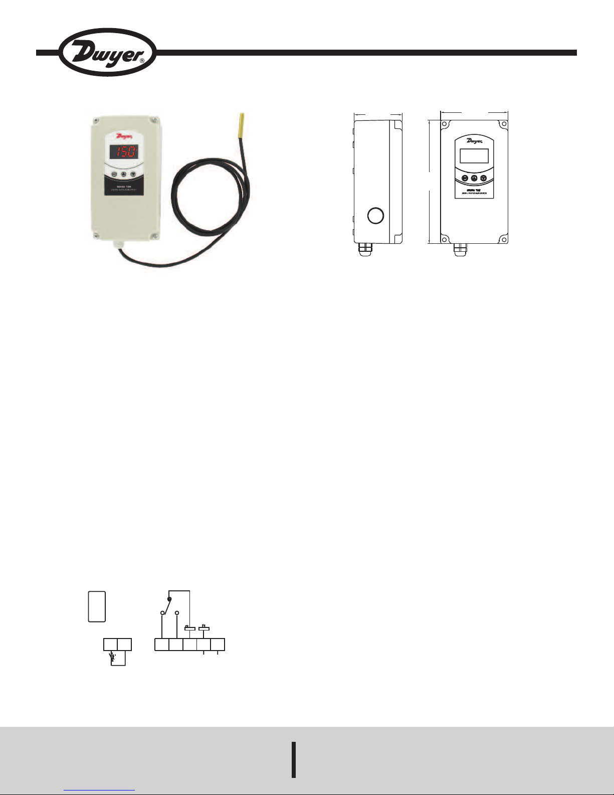
Series TSW Single Stage Digital Temperature Switch
Specifications - Installation and Operating Instructions
he Series TSW Digital Temperature Switch combines the trusted, reliable TS
T
amily of temperature controls and an installation friendly weatherproof enclosure.
f
y using the same programming parameters as our Series TS2 and Series TSS2,
B
set up can be quickly completed using the front keys or by using the TS2-K configuration key. In order to prevent tampering from unauthorized users, a parameter lock physical jumper and software passcode security are standard in the unit.
The bright, easy-to-read LED display shows the current output status and the temperature measurement.
The multiple conduit knockouts on the Series TSW give flexibility to the installer to
determine the best location for the conduit entry. Another installation friendly feature of the Series TSW is the ability to quickly jumper the line voltage to the common of the output relay using fast tabs.
INSTALLATION
NOTICE: The thermostat must be installed by authorized professionals. It should
be located in a place free of vibrators, impacts, and corrosive gases.
NOTICE: Protective plastic overlay should be peeled off after final installation.
WIRING INSTRUCTIONS
Wiring diagram is displayed on the inside cover of the unit and in figure 1.
NOTICE: If the length of the probe cables measures more than 100 meters, a
recalibration adjustment must be made (parameter P1).
NOTICE: Avoid installing the probe cables in proximity with any power cables.
SPECIFICATIONS
Probe Range:
TC: -58 to 302°F (-50 to 150°C).
P
NTC: -58 to 230°F (-50 to 110°C).
Input: PTC (1000 Ω @ 25°C)/NTC (10KΩ @ 25°C).
Output: R1 SPDT Relay Resistive Load: 20A @ 240 VAC.
Horsepower Rating: R1 2HP @240 VAC.
Control Type: On/Off.
Power Requirements: 90 to 255 VAC or 12 to 24 VAC/VDC (±10%) depending
on model.
Power Consumption: 3.6VA.
Accuracy: ±1% FS.
Display: 3 digits plus sign.
Resolution: 0.1° < 100°; 1° ≥ 100°.
Memory Backup: Non-volatile memory.
Ambient Temperature: 32 to 104°F (0 to 40°C).
Weight: 1.2 lbs (544 g).
Front Protection: NEMA 4X (IP66).
Agency Approvals: CE, UL, cUL.
DWYER INSTRUMENTS, INC.
P.O. BOX 373 • MICHIGAN CITY, INDIANA 46360, U.S.A. Fax: 219/872-9057 e-mail: info@dwyermail.com
Figure 1
Phone: 219/879-8000 www.dwyer-inst.com
Page 2
PROGRAMMING PARAMETERS
n order to adjust parameters, jumper must be set in unlocked position.
I
Locked Unlocked
igure 2
F
ccess only to Set Points SP (without software code protection):
A
Press and release SET. Parameter SP appears on the display.
•
Press SET to see the value of the parameter.
•
• Modify the value using the UP and DOWN keys.
• Press SET Key to save the value.
• Press SET and DOWN to quit programming, or wait 1 minute for the
IMEOUT.
T
ccess to all parameters (software code protected):
A
• Press SET for 8 seconds. The access code value 0 is shown on the
display.
• Using the UP and DOWN buttons, set the code (factory-set code is 0).
• Press SET to confirm the code. If it is correct, the first parameter label
ill be shown on the display (SP).
w
Move to the desired parameter with the UP and DOWN keys.
•
Press SET to see the value of the parameter.
•
• Modify the value with the UP and DOWN keys.
• Press SET to save and exit parameter list.
• Press SET and DOWN to quit programming, or wait 1 minute for the
TIMEOUT.
esetting the parameter pass code
R
he parameter code can be set to zero by holding the SET key and cycling power
T
to the unit.
Silence the Buzzer
Pressing the SET and DOWN keys simultaneously silences the buzzer. The message of alarm continues appearing in the display.
PARAMETER DESCRIPTIONS
P = Set Point. Temperature desired to regulate the machine. Can vary from r1 to
S
2.
r
0 = Differential. Heating: If temperature is ≥ SP then output is OFF. If temperature
r
s < SP - r0 then output is ON. Cooling: If temperature is ≥ SP + r0 then output is
i
ON. If temperature is < SP then output is OFF.
r1 = Lower Set Point Limit.
r2 = Upper Set Point Limit.
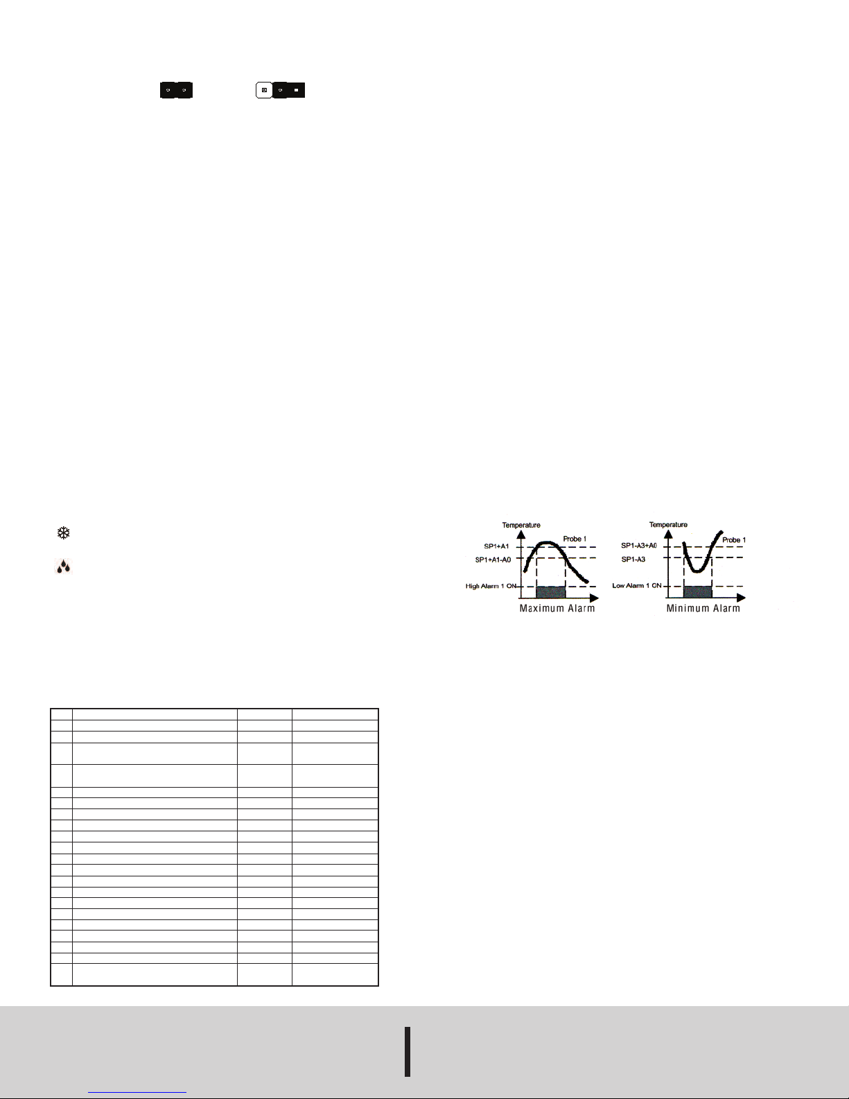
0=Alarm differential. It is the temperature differential between the alarm On and
A
ff cycle.
O
1=Maximum alarm probe1.
A
aximum alarm ON when probe 1 higher than SP1+A1
M
Maximum alarm OFF when probe 1 lower than SP1+A1-A0.
A3=Minimum alarm probe1.
Minimum alarm ON when probe 1 lower than SP1-A3
inimum alarm OFF when probe 1 higher than SP1-A3+A0.
M
5=Alarm verification time. Time from the alarm event until it trips.
A
6=Alarm probe 1 selection. (See Figure 3).
A
AHL=Maximum and minimum alarm probe 1 enabled.
Ano=No alarms probe 1.
AH=Maximum alarm probe 1 enabled.
AL=Minimum alarm probe 1 enabled.
0 = Heat or Cooling Control. Ht = heating control, Co = cooling control.
d
2 = Defrosting Time Remaining, in minutes. If d2 = 0, defrosting will not start.
d
8 = Interval Between Two Defrostings, in hours.
d
c0 = Minimum Time for Compressor to be OFF. Minimum time for compressor to
stop until it can start again.
c1 = Continuous Cycle Time. The remaining time for a continuous cold cycle.
c2 = ON Time of fault cycle, during probe error.
3 = OFF Time of fault cycle, during probe error.
c
0 = Selection of Engineering units between F and C.
P
1 = Ambient Probe Calibration. Offsets temperature in degrees to adjust the
P
ambient probe.
H5 = Access Code to Parameters. Factory-set to 0.
H6 = Selection of Input Probe Type: PTC or NTC.
t0 = Temperature Display Limit. Maximum temperature shown on the display,
although the real temperature can be greater.
LED INDICATIONS
This indicates that the output is energized or that the compressor is
connected. It waits for the programmed minimum stop time of the
compressor.
This indicates that defrosting is activated.
Error Messages
In normal operation, the probe temperature will be shown. In case of alarm or error,
the following messages will be shown:
• Er- Memory error.
• AH1 Maximum temperature alarm, probe 1.
• AL1 Minimum temperature alarm, probe 1.
• -- Shorted-circuited probe error.
• oo- Open probe error.
Parameter List
Description
SP
Set Point
r0
Differential or hysteresis
r1
Lower value for set point
r2
Higher value for set point
A0
Alarm differential
A1
Maximum alarm probe 1
A3
Minimum alarm probe 1
A5
Alarm verification time
A6
Alarm probe 1 selection
d0
Heating or Cooling Control
d2
Time for Defrosting
d8
Interval time between Defrosts
c0
Minimum stop time for compressor
c1
Continuous cycle time
c2
On time of fault cycle
c3
Off time of fault cycle
P0
Engineering Units
P1
Ambient Probe Adjustment
H5
Parameter acess code
H6
Probe Input Type
t0
Maximum Temperature on Display
©Copyright 2014 Dwyer Instruments, Inc. Printed in U.S.A. 7/14 FR# R0-443773-10 Rev. 1
Units
Degrees
Degrees
Degrees
Degrees
Degrees
Degrees
Degrees
h-m(*)
Option
Option
Minutes
Hours
Minutes
Hours
Minutes
Minutes
Option
Degrees
Number
Option
Degrees
Range
r1 to r2
1 to 20°
-50 to 150°C
-50 to 302°F
-50 to 150°C
-50 to 302°F
0.1 to 20.0
0.1 to 99.9
0.1 to 99.9
0.0 to 18.0
AHL, ANo, AH, AL
Ht/Co
0 to 59
0 to 24
0 to 59
0 to 24
0 to 999
0 to 999
°C/°F
-10 to 10°
0 to 99
Ptc/ntc
-50 to 150°C
-50 to 302°F
OPERATION IN CASE OF ERROR
If the probe or thermostat memory should fail, the compressor will be connected in
accordance to the parameters set in C2 and C3.
MAINTENANCE/REPAIR
Upon final installation of the Series TSW, no routine maintenance is required. The
Series TSW is not field serviceable and should be returned if repair is needed. Field
repair should not be attempted and may void warranty.
WARRANTY/RETURN
Refer to “Terms and Conditions of Sales” in our catalog and on our website. Contact
customer service to receive a Return Goods Authorization number before shipping
the product back for repair. Be sure to include a brief description of the problem
plus any additional application notes.
Dwyer Instruments,Inc.
Attn: Repair Department
102 Highway 212
Michigan City, IN 46360 U.S.A.
Figure 3
DWYER INSTRUMENTS, INC.
Phone: 219/879-8000 www.dwyer-inst.com
P.O. BOX 373 • MICHIGAN CITY, INDIANA 46360, U.S.A. Fax: 219/872-9057 e-mail: info@dwyermail.com
 Loading...