

Page 1
Bulletin T-TS2
Series TS2- Digital Temperature Switch
Specifications - Installation and Operating Instructions
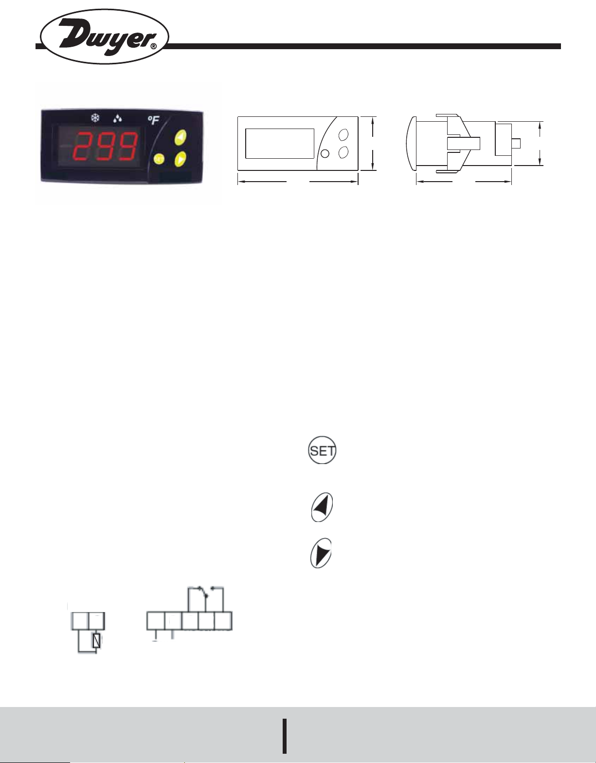
DESCRIPTION
Monitor and control temperature for heating and cooling applications with
the Series TS2 Digital Temperature Switch. The Series TS2 offers twelve
programmable functions to customize the unit to fit application requirements. Use the 15(5) Amp SPDT relay output to drive a motor, compressor, or fan. Designed with the OEM in mind, the TS2 offers the ability to
configure multiple units with the touch of a button.
Programming multiple units is quick and easy. Simply program one switch
with the desired parameter settings and connect the configuration key
(sold separately) to the back of the unit. Press the button on the configuration key and download the parameter settings. Connect the key to the
other switches to upload the stored settings with the push of a button.
The TS2 features set point adjustments, static defrost timing, compressor
mean time, hysteresis, and ambient probe adjustment. Security protection is offered using a password code. The Series TS2 Digital
Temperature Switches are designed to operate with PTC (1000Ω @
25°C) probes sold separately.
INSTALLATION
The thermostat must be installed by authorized professionals. It should
be located in a place free of vibrations, impacts, water and corrosive
gases.
A hole measuring 71 x 29 mm must be cut in the panel where the thermostat is to be fitted (apply silicone to make it leaktight). Then, the fixing
cups must be fitted, sliding them onto the thermostat until secure. Do not
force tightening of the screw if the U-brackets are used. The connections
must be covered with the rear cover for this.
WIRING INSTRUCTIONS
Avoid installing the probe’s cables in proximity with any power cable. If
the length of the probe cables measures more than 100 meters, a recalibration adjustment must be made (parameter P1).
250 VAC 15(5)A 30 LRA
Probe Input
89
2
1
t°
7
Power
Supply
10
OUTPUT
11
(1.338)
(3.000)
SPECIFICATIONS
Probe Range: -58 to 302°F (-50° to 150°C).
Input: PTC thermistor 1000Ω @ 25°C.
Output: 15A PTC SPDT relay @ 250 VAC resistive, 5A inductive.
Horsepower Rating (HP): 3/4 HP.
Control Type: ON/OFF.
Power Requirements: 110 VAC.
Accuracy: ±1°C.
Display: 3-digit, Red, 1/2˝ digits.
Resolution: ±1 digit.
Memory Backup: Nonvolatile memory.
Ambient Operating Temperature: 14 to 158°F (-10 to 70°C).
Storage Temperature: -4 to 176°F (-20° to 80°C).
Weight: 2.3 oz (65 g).
Front Panel Rating: NEMA 4X (IP65).
Agency Approvals: CE, URc, UR.
FRONT OPERATION
PUSH BUTTONS
Pushing SET once gives access to the SP. Pushing for 8 seconds gives way to the requested code. After entering the correct code, all parameters are accessible. This button alternates
between text parameters and their value. It validates the modified parameters. When pressed with DOWN, it exits parameter
programming.
Pressing this arrow allows the user to go to the next parameter
or increase the value viewed on the display. When pressed for
8 seconds, it activates or deactivates defrosting.
Pressing this arrow allows the user to go to the previous parameter or decreases the value viewed on the display. When
pressed for 8 seconds, it activates or deactivates the continuous
cooling cycle. When pressed simultaneously with SET, it exits
the programming mode.
PROGRAMMING PARAMETERS
Access only to Set Point SP (without code protection):
•Press and release SET. SP text appears on the display.
•Press SET again. The real value is shown on the display.
•Modify the value using the UP and DOWN keys.
•Press SET and DOWN to quit programming, or wait 1 minute for the
TIMEOUT.
Access to all parameters (code protected):
•Press SET for 8 seconds. The access code value 00 is shown on the display.
•Using the UP and DOWN buttons, set the code (factory-set code is 00).
(2.375)
(1.100)
DWYER INSTRUMENTS, INC.
Phone: 219/879-8000 www.dwyer-inst.com
P.O. BOX 373 • MICHIGAN CITY, INDIANA 46361, U.S.A. Fax: 219/872-9057 e-mail: info@dwyer-inst.com
Page 2
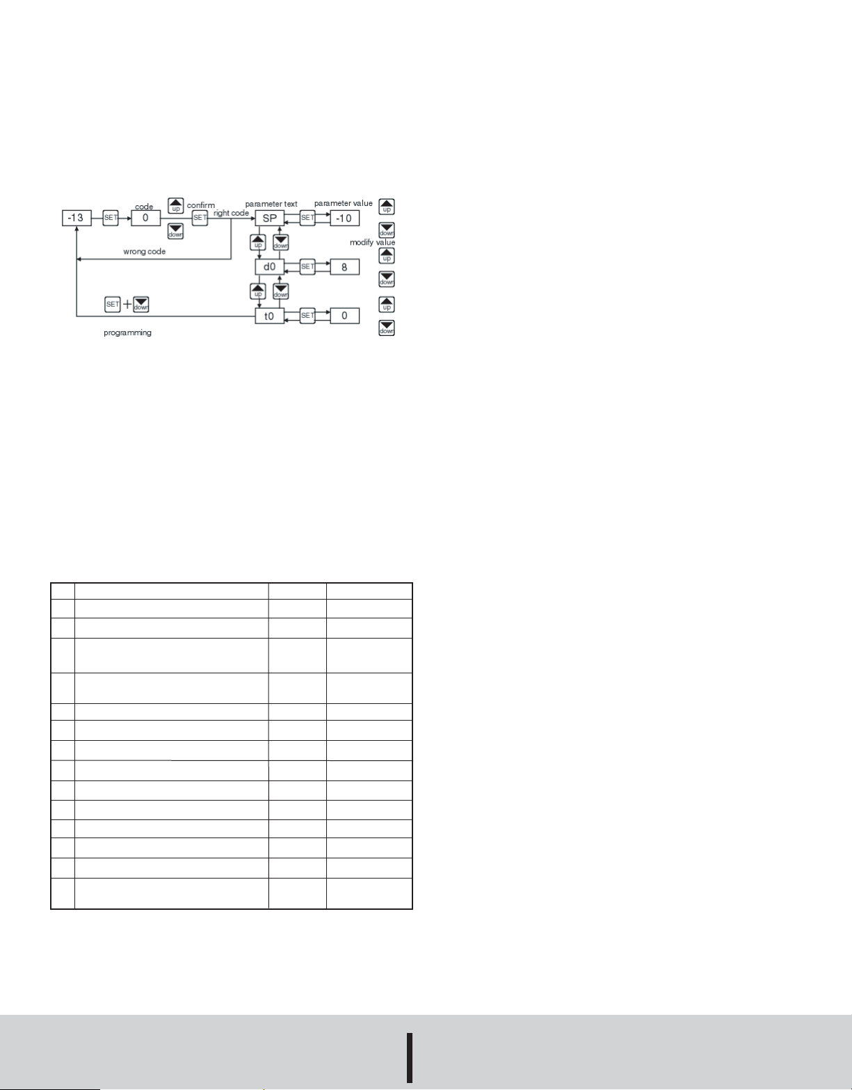
•Press SET to enter the code. If it is correct, the first parameter label will
be shown on the display (SP).
•Move to the desired parameter with the UP and DOWN keys.
•Press SET to see the value.
•Modify the value with the UP and DOWN keys.
•Press SET to enter it, and exit to text parameter.
•Press SET and DOWN to quit programming, or wait 1 minute for the
TIMEOUT.
SETTING THE KEYBOARD CODE TO ZERO
exits
The keyboard code can be set to zero by holding the SET key and turning the controller off then on again.
LED INDICATIONS
Out: This indicates that the compressor is connected. It waits the programmed minimum stop time of the compressor.
Def: This indicates that defrosting is activated.
MESSAGES DISPLAY
In normal operation, the probe temperature will be shown. In case of
alarm or error, the following messages will be shown:
• Er- Memory error.
• -- Short-circuited probe error.
• oo- Open probe error.
Description
SP
Set point
r0
Differential or hysteresis
r1
Lower value for set point
r2
Higher value for set point
d0
Heating or cooling control
d2
Time for defrosting
d8
Interval time between defrosting
c0
Minimum stop time for compressor
c1
Continuous cycle time
c2
ON time of fault cycle
c3
OFF time of fault cycle
P1
Ambient probe adjustment
H5
Parameter access code
t0
Maximum temperature on display
Units
degrees
degrees
degrees
degrees
option
minutes
hours
minutes
hours
minutes
minutes
degrees
numeric
degrees
Range
r1 to r2
1 to 20°
-50 to 150°C
-50 to 302°F
-50 to 150°C
-50 to 302°F
Ht/Co
0 to 59’
0 to 24
0 to 59’
0 to 24
0 to 999
0 to 999
-10° to 10°
0 to 99
-50 to 150°C
-50 to 302°F
PARAMETERS
PARAMETER DESCRIPTIONS
SP = Set Point. Temperature wished to regulate the machine. Can vary
from r1 to r2.
r0 = Differential. Heating: If temperature is ≥ Set then out OFF. If temperature is ≤ Set then out OFF. Cooling: if temperature is > Set + r0 then
out ON. If temperature is ≤ Set then out OFF.
r1 = Lower Set Point Limit
r2 = Higher Set Point Limit
d0 = Heat or Cooling Control. Ht = heating control, Co = cooling con-
trol.
d2 = Defrosting Time Remaining, in minutes. If d2 = 0, defrosting will
not start.
d8 = Interval Between Two Defrostings, in hours.
c0 = Minimum time for compressor to be OFF. Minimum time from
when the compressor stops till it connects again.
c1 = Continuous Cycle Time. The remaining time for a continuous cold
cycle.
c2 = ON time of fault cycle, during probe error.
c3 = OFF time of fault cycle, during probe error.
P1 = Ambient Probe Calibration. Offsets degrees to adjust the ambient
probe.
H5 = Access Code to Parameters. Factory-set as 00.
t0 = Temperature Display Limit. Maximum temperature shown on the
display, although the real temperature can be greater.
OPERATION IN CASE OF ERROR
If the probe or thermostat memory should fail, the compressor will be connected for 5 minutes ON then 5 minutes OFF.
MAINTENANCE
CLEANING
Clean the surface of the display controller with a soft, damp cloth. Never
use abrasive detergents, petrol, alcohol or solvents.
REPAIRS
After final installation of the TS Series Digital Temperature Switch, no routine maintenance is required. A periodic check of system calibration is recommended. The devices are not field repairable and should be returned
to the factory if recalibration or other service is required. After first obtaining a Returned Goods Authorization (RGA) number, send the material,
freight prepaid, to the following address. Please include a clear
description of the problem plus any application information
available.
Dwyer Instruments,Inc.
Attn: Repair Department
102 Highway 212
Michigan City, IN 46360 U.S.A
©Copyright 2009 Dwyer Instruments, Inc. Printed in U.S.A. 8/09 FR# R7-443771-00 Rev.1
DWYER INSTRUMENTS, INC.
Phone: 219/879-8000 www.dwyer-inst.com
P.O. BOX 373 • MICHIGAN CITY, INDIANA 46361, U.S.A. Fax: 219/872-9057 e-mail: info@dwyer-inst.com
 Loading...