

Page 1
Model TBU-00 Temperature Transmitter
TO PC USB PORT
®
Specications - Installation and Operating Instructions
Bulletin T-TBU-00
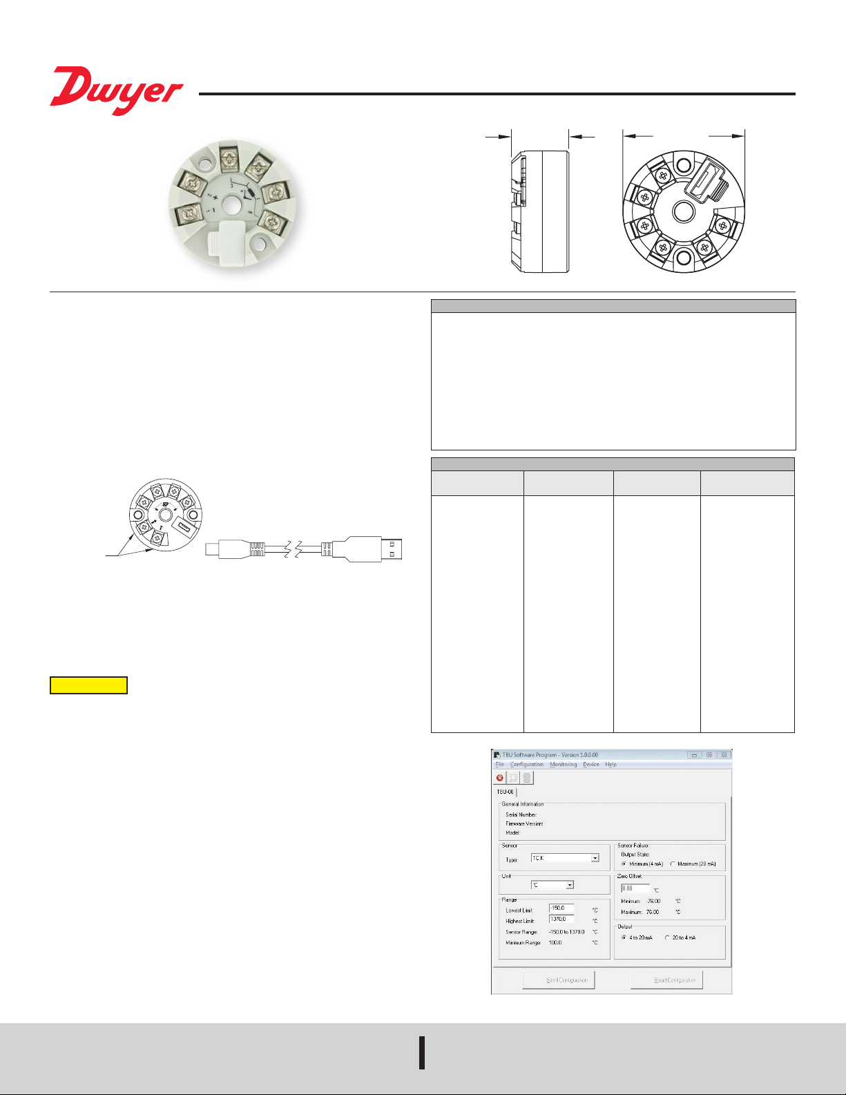
The Model TBU-00 Temperature Transmitter is a high precision temperature
transmitter designed to easily mount in most temperature sensor instrument
enclosures. The universal input reduces inventory while the micro-USB port facilitates
easy conguration, and calibration in the lab or in the eld. The versatile TBU
model allows for selection and conguration of input type, measurement range, and
calibration. The output can be set as either direct 4 to 20 mA, or reverse 20 to 4 mA,
through easy to use conguration software.
Conguration
During the setup, the transmitter is powered by the USB, and does not require an
external power supply. See Figure 1. The transmitter setup can also be made by
connecting it to the loop using the loop power supply. There is no electrical insulation
between the transmitter and the communication port (interface), therefore do not
congure the transmitter when it is connected to the process.
PLUG A
POWERED
CURRENTS
LOOP
FACTORY SETTING AND CONFIGURATION
When the transmitter is used with the factory setting, no further action is required
and the transmitter is ready to be installed. Changes to the conguration are possible
through the TBU software, provided free of charge on the Dwyer website. The factory
setting for the TBU is for a Pt100 3-wire sensor with a range of 0 to 100°C with 0°C
zero correction and an output of 4 to 20 mA.
CAUTION
equipment is powered may result in equipment damage.
After these connections, the user must run the TBU software. See Figure 2 for software
screen.
TRANSMITTER USB CABLE
Figure 1: USB cable connections
The USB communication port (micro-USB) of the TBU-00 is not
electrically insulated from the transmitters input. Connection while
MICRO B
13/16 [20.5]
SPECIFICATIONS
Input: Thermocouples J, K, R, S, T, N, E, and B; 2, 3, or 4 wire Pt100 RTD, 2 or 3
wire Pt1000 RTD, 2 wire NTC thermistor, or 0 to 50 mV voltage.
Output: Linearized 4 to 20 mA, 2 wire or 20 to 4 mA loop powered.
Transmitter Type: 2, 3, or 4 wire.
Temperature Limits: -40°F to 185°F (-40 to 85°C).
Power Requirements: 10 to 35 VDC.
Accuracy: See chart below.
Temperature Drift: < ±0.16% / 25°C.
Response Time: 1.6 s, typical.
Weight: 1.4 oz (40 g).
Agency Approvals: CE.
ACCURACY CHART
Input Type
Voltage
Thermocouple J
Thermocouple K
Thermocouple R/S
Thermocouple T
Thermocouple N
Thermocouple E
Thermocouple B
Pt100/Pt1000 RTDs
NTC Thermistor
Max. Temperature
Range
0 to 50 mV
-148 to 1400°F
(-100 to 760°C)
-238 to 2498°F
(-150 to 1370°C)
-58 to 3200°F
(-50 to 1760°C)
-256 to 752°F
(-160 to 400°C)
-454 to 2372°F
(-270 to 1300°C)
-130 to 1328°F
(-90 to 720°C)
932 to 3308°F
(500 to 1820°C)
-328 to 1202°F
(-200 to 650°C)
-22 to 248°F
(-30 to 120°C)
1-23/32 [43.5]
Min. Temperature
Range Accuracy (Typical)
5 mV
212°F (100°C)
212°F (100°C)
752°F (400°C)
212°F (100°C)
212°F (100°C)
212°F (100°C)
752°F (400°C)
104°F (40°C)
104°F (40°C)
±0.1% FS
±0.1% FS
±0.1% FS
±0.1% FS
±0.1% FS
±0.1% FS
±0.1% FS
±0.1% FS
±0.13% FS
±0.3°C
The elds in the software screen pictured in Figure 2 mean:
1. General Information: This eld shows information that identies the transmitter.
This information could be sent to Dwyer Instruments when additional technical
assistance is requested.
2. Sensor: Select the type of sensor to be used.
3. Measuring Range: Sets the measurement range of the transmitter.
Lower Range Limit: Equivalent temperature for a current of 4 mA.
Upper Range Limit: Equivalent temperature for a current of 20 mA.
Sensor Range: The values chosen cannot exceed the range of the sensor.
Minimum Range: Do not set a lower band (span) than the minimum range indicated.
4. Sensor Failure: Establishes the output behavior when the transmitter indicates a
failure.
Minimum: Output current goes to < 3.6 mA (down-scale), typically used for
refrigeration.
Maximum: Output current goes to > 22.0 mA (up-scale), typically used for heating.
5. Zero Offset: Offset allowing for small deviations presented in the transmitter output.
6. Send Conguration: Once set, the setup will be uploaded to the transmitter.
7. Read Conguration: Reads the current setup in the connected transmitter.
DWYER INSTRUMENTS, INC.
P.O. BOX 373 • MICHIGAN CITY, INDIANA 46360, U.S.A.
Figure 2: Software screenshot
Phone: 219/879-8000
Fax: 219/872-9057
www.dwyer-inst.com
e-mail: info@dwyermail.com
Page 2
MECHANICAL INSTALLATION
Pt100 SENSOR
The TBU-00 transmitter is suitable to be installed in instrument enclosures. Vibrations,
moisture, extreme temperatures, electro-magnetic interference, high voltage, and
other interferences can permanently damage the unit, and could cause an error in the
measured value.
Pt100 SENSOR
4-WIRE
ELECTRICAL INSTALLATION
Recommended wire size: 26 AWG to 16 AWG (0.14 to 1.5 mm
2
).
Recommended terminal torque: 7.08 in-lbf (0.8 Nm).
RECOMMENDATIONS FOR INSTALLATION
Separate signal lines from facility power lines. The use of grounded conduit is
recommended.
The instrument must be powered from the instrumentation power supply circuit.
Transient suppression should be used with inductive loads such as contact coils and
solenoids.
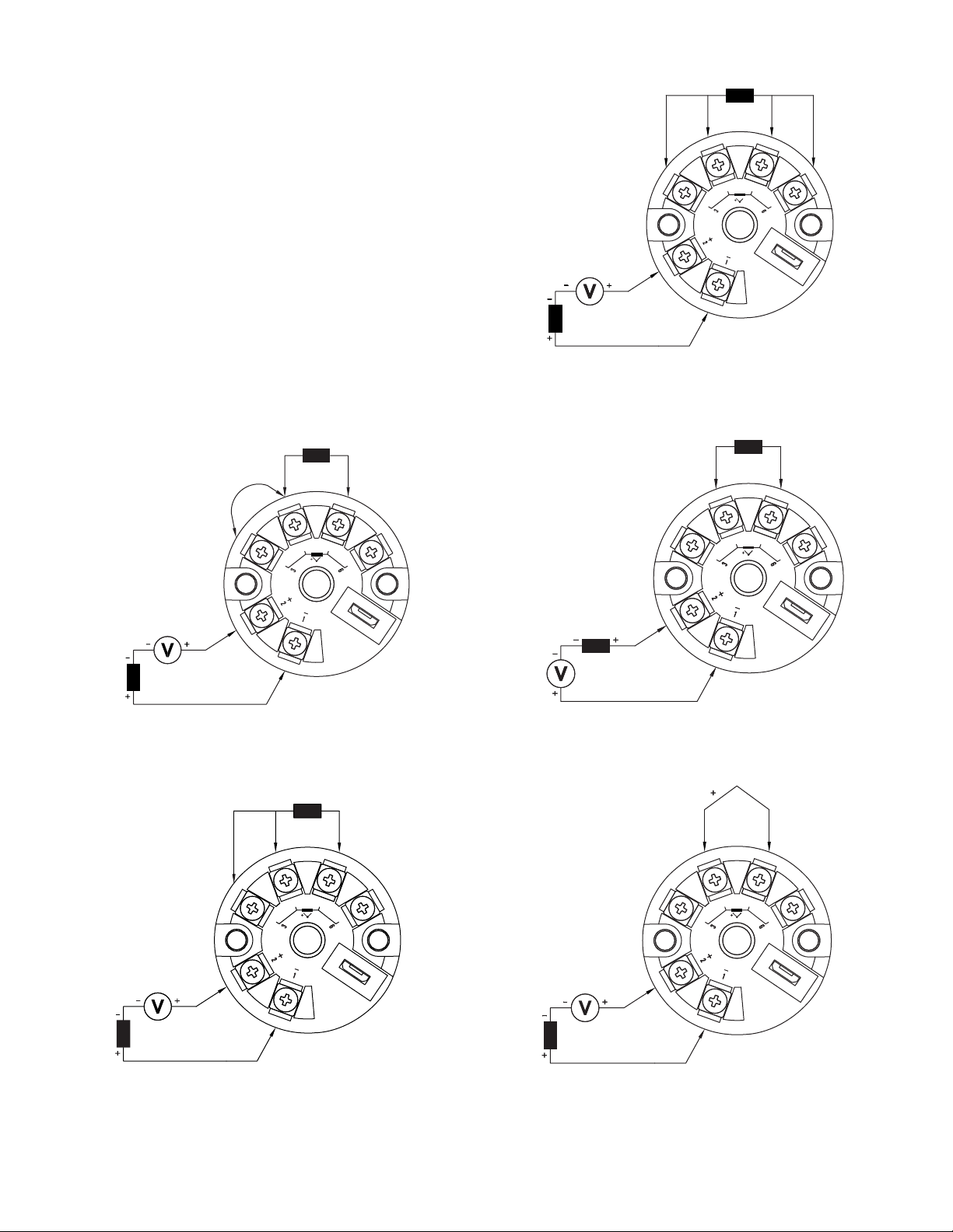
ELECTRICAL CONNECTIONS
The gures below shows the electrical connections required. Terminals 3, 4, 5 and
6 are dedicated to the sensor connection. LOAD represents the 4 to 20 mA current
measuring device (indicator, controller, recorder, etc.).
Note: When using a Pt100Ω 2-wire RTD, terminals 3 and 4 must be interconnected,
according to Figure 3 below. The Pt100 wire length should be less than 12 in (30 cm)
to maintain the measurement error within specications (electrical resistance).
2-WIRE
JUMPER
LOAD
POWER
SUPPLY
Figure 5: Pt100 4-wire
NTC SENSOR
2-WIRE
TRANSMITTER
LOAD
LOAD
POWER
SUPPLY
POWER
SUPPLY
Figure 3: Pt100 2-wire
Pt100 SENSOR
3-WIRE
TRANSMITTER
TRANSMITTER
POWER
SUPPLY
LOAD
LOAD
POWER
SUPPLY
Figure 6: NTC 2-wire
THERMOCOUPLE
SENSOR
TRANSMITTER
TRANSMITTER
Figure 7: ThermocouplesFigure 4: Pt100 3-wire
Page 3

POWER
SUPPLY
0 to 50 mV
SUPPORT
This product contains no serviceable parts inside. For troubleshooting, visit our
frequently asked questions at www.dwyer-inst.com or contact our technical support
team at 1-800-872-9141.
MAINTENANCE/REPAIR
Upon nal installation of the Model TBU, no routine maintenance is required. The
Model TBU is not eld serviceable and is not possible to repair the unit. Field repair
should not be attempted and may void warranty.
WARRANTY/RETURN
Refer to “Terms and Conditions of Sale” in our catalog and on our website. Contact
customer service to receive a Return Goods Authorization number before shipping the
product back for repair. Be sure to include a brief description of the problem plus any
additional application notes.
LOAD
Figure 8: Voltage (0 to 50 mV)
OPERATION
The sensor offset can be changed through the TBU-00 software. The USB cable may
be connected to the transmitter without causing any measurement errors. See item 5
Zero Offset on the rst page of this manual.
The user must choose the most suitable sensor and range to the process. The selected
range must not exceed the maximum range of measurement dened for the sensor
and should not be smaller than the minimum range for the same sensor.
Note: The transmitter accuracy is based on the maximum range of the sensor used,
even when a narrower range is programmed.
Example:
• The Pt100 sensor in the range 0 to 100°C and accuracy of 0.12%, the maximum
error will be 1.02°C (0.12% of 850 °C )
• The Pt100 sensor in the range of 500 to 600°C and accuracy of 0.19%, the maximum
error will be 1.61°C (0.19% of the 850°C )
Note: When the measurements are made at the transmitter, ensure the Pt100
excitation current required by the calibrator is compatible with the Pt100 excitation
current used in the transmitter: 0.8 mA.
SAFETY INFORMATION
Any control system design should take into account that any part of the system has the
potential to fail. This product is not a protection or safety device and its alarms are not
intended to protect against product failures. Independent safety devices should always
be provided if personnel or property are at risk.
TRANSMITTER
Product performance and specications may be affected by its environment and
installation. It’s the responsibility of the user to assure proper grounding, shielding,
cable routing, and electrical noise ltering are in accordance with local regulations,
EMC standards, and good installation practices.
Page 4

NOTES
__________________________________________________________________________________________________________________________________________
__________________________________________________________________________________________________________________________________________
__________________________________________________________________________________________________________________________________________
__________________________________________________________________________________________________________________________________________
__________________________________________________________________________________________________________________________________________
__________________________________________________________________________________________________________________________________________
__________________________________________________________________________________________________________________________________________
__________________________________________________________________________________________________________________________________________
__________________________________________________________________________________________________________________________________________
__________________________________________________________________________________________________________________________________________
__________________________________________________________________________________________________________________________________________
__________________________________________________________________________________________________________________________________________
__________________________________________________________________________________________________________________________________________
__________________________________________________________________________________________________________________________________________
__________________________________________________________________________________________________________________________________________
__________________________________________________________________________________________________________________________________________
__________________________________________________________________________________________________________________________________________
__________________________________________________________________________________________________________________________________________
__________________________________________________________________________________________________________________________________________
__________________________________________________________________________________________________________________________________________
__________________________________________________________________________________________________________________________________________
__________________________________________________________________________________________________________________________________________
__________________________________________________________________________________________________________________________________________
__________________________________________________________________________________________________________________________________________
__________________________________________________________________________________________________________________________________________
__________________________________________________________________________________________________________________________________________
Printed in U.S.A. 5/19 FR# 444508-00 Rev. 1©Copyright 2019 Dwyer Instruments, Inc.
DWYER INSTRUMENTS, INC.
P.O. BOX 373 • MICHIGAN CITY, INDIANA 46360, U.S.A.
Phone: 219/879-8000
Fax: 219/872-9057
www.dwyer-inst.com
e-mail: info@dwyermail.com
 Loading...