

Page 1
SERIES TUF | ULTRASONIC ENERGY METER
®
FEATURES/BENEFITS
• Lower maintenance costs with local parameter display and no moving parts
• BACnet MS/TP or Modbus® RTU data communication protocol output allows for easy transfer of data
• Flow and temperature monitor in one unit eliminates the need for multiple units
• Produced to meet EN1434 MID approval for accuracy and quality
DESCRIPTIONAPPLICATIONS
• Heat metering
• Utilities billing
• Tenant billing
• Monitoring of water heating or cooling: radiators, fan coils
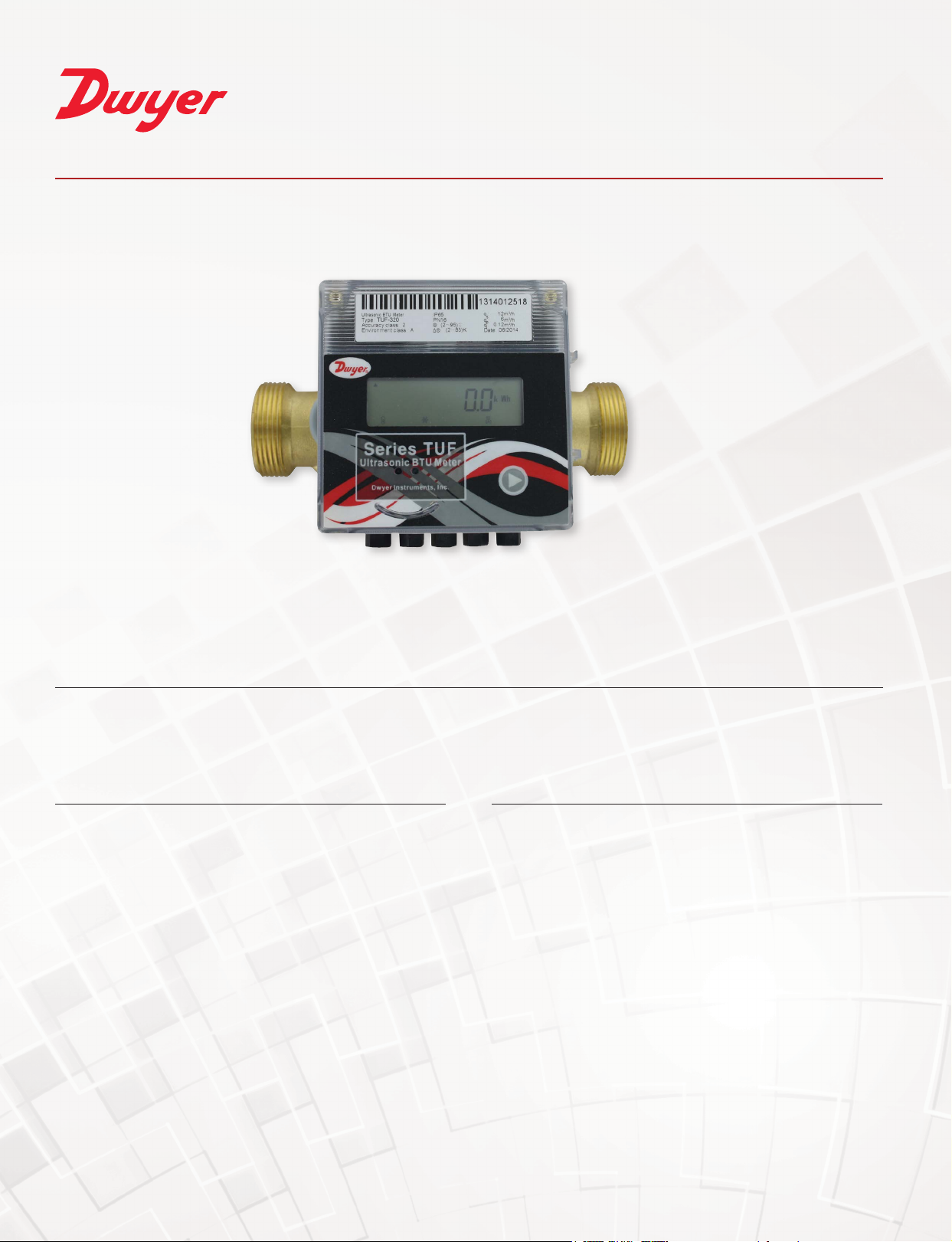
The Series TUF Ultrasonic Energy Meter is a highly accurate and
stable energy meter. It utilizes ultrasonic technology to measure heating
and cooling energy consumption. The Series TUF incorporates a
owmeter, temperature meter, and a calculator into a single, compact
unit. The size and lack of moving parts means the Series TUF requires
minimal maintenance. The 8-digit LED display enables easy reading of
the meter’s recorded values; including temperature, ow-rate, energy
consumption, etc. These features make it ideal for installation on chillers,
boilers, and individual apartment piping. With the optional couplings it
is capable of being used with either NPT or BSPT pipe sizes. It is the
perfect meter for tenant billing applications.
Modbus® is a registered trademark of Schneider Automation, Inc.
Page 2
Service Clean, compatible liquids.
4-1/4
T
2.8´ WATER-IN
FLOW SENSOR
DNXX
H
4-1/4
[108.00]
L
[2 COMMUNICATION,
2 POWER]
4´ RETURN PIPE
TEMP SENSOR
2X D
THREAD
4´ FLOW PIPE
TEMP SENSOR
2.8´ WATER-OUT
FLOW SENSOR
2.8´ WATER-IN
FLOW SENSOR
4´ 4-CORE
WIRE
BALL
BALL
Y
D
TEMPERATURE SENSOR
Wetted Materials Brass and 316L SS.
Range See chart.
Display 8-digit LED.
Accuracy BTU: EN1434/CJ128 Class 2; Flow: ±(2+(0.02 Qp/Q))%; Temperature: ±0.1°C.
Power Requirements 24 VAC/VDC (model dependent) or 3.6 V ER26500 lithium metal battery, user supplied and installed, battery acts as
back-up if power is lost.
Power Consumption 1 W.
Temperature Limits Ambient: 41 to 131°F (5 to 55°C); Process: 36 to 203°F (2 to 95°C).
Humidity Limit <93%.
Pressure Limits 232 psi (16 bar) for DN15 to DN40; 362 psi (25 bar) for >DN50.
Pressure Drop <1.5 psi (10 kPa).
Process Connection See chart.
Serial Communications Modbus® RTU or BACnet MSTP (selectable)**.
Enclosure Rating IP65.
Enclosure Material Plastic.
Repeatability Flowmeter: 1%.
Electric Connections 3 ft (0.91 m) 4x0.2 mm2 cable with terminal block.
Flow Direction Unidirectional.
Mounting Orientation Horizontal or vertical.
Weight See chart.
Agency Approvals CE.
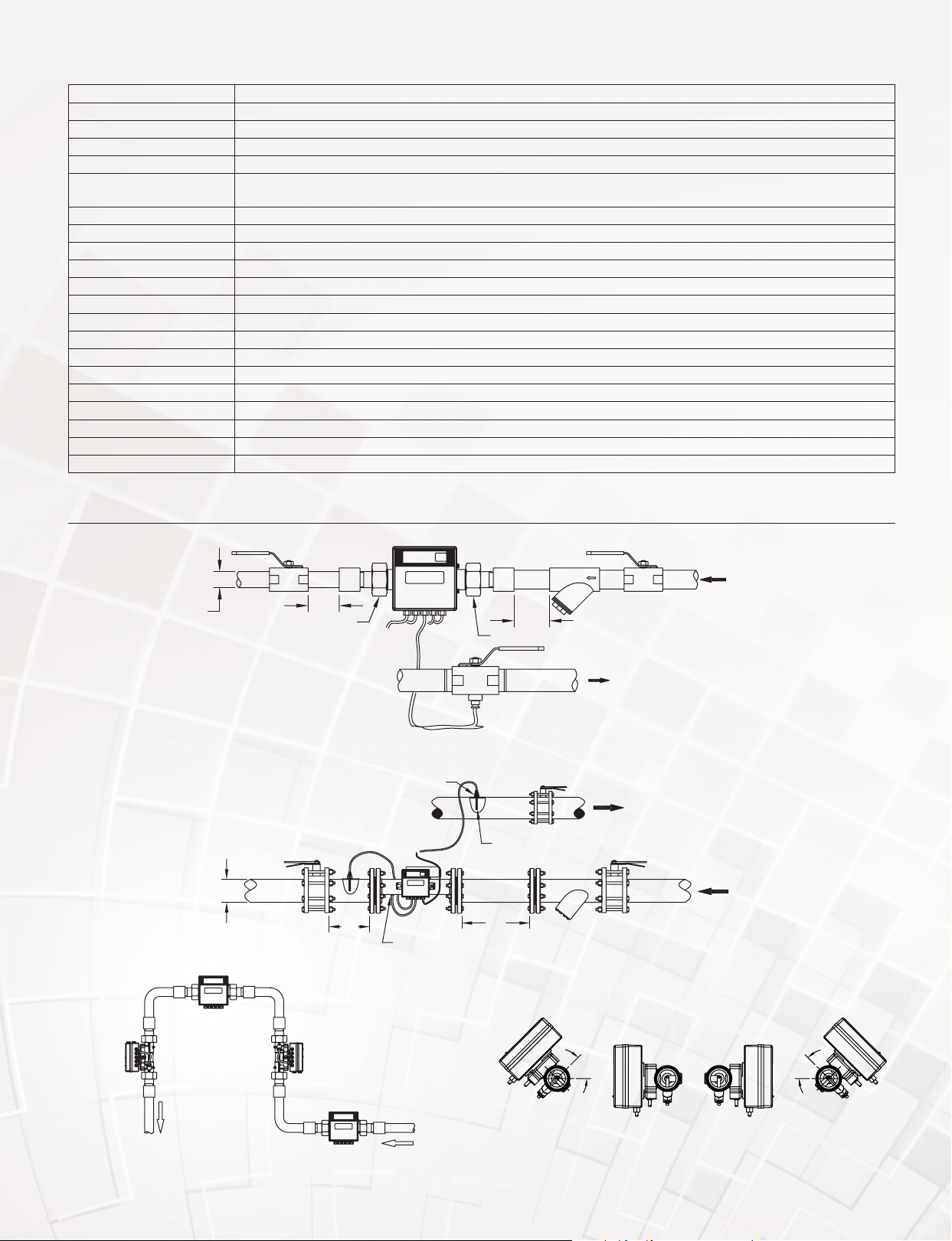
INSTALLATION
VALV E
STRAIGHT
JOINT
5D
UNION NUT
STRAIGHT
JOINT
FILTER
PIPEPIPEPIPE PIPE PIPE
10D
UNION NUT
WATER RETURN
BALL
VALV E
VALV E
WATER SUPPL
Installation diagram for TUF-150/400
D
BUTTERFLY
VALV E
PIPE PIPE
5D
SENSOR
SLEEVE
SUPPLY WATER
BUTTERFLY
VALV E
RETURN WATER
TEMPERATURE
SENSOR
10D
FILTER
WATER RETURN
BUTTERFLY
VALV E
WATER SUPPLY
Installation diagram for TUF-500/2000
45° MIN.
Installation positions Mounting rotation
45° MIN.
Page 3

DIMENSIONS AND WIRING DIAGRAMSPECIFICATIONS
4-1/4
T
2.8´ WATER-IN
FLOW SENSOR
DNXX
H
4-1/4
[108.00]
L
[2 COMMUNICATION,
2 POWER]
4´ RETURN PIPE
TEMP SENSOR
2X D
THREAD
4´ FLOW PIPE
TEMP SENSOR
2.8´ WATER-OUT
FLOW SENSOR
2.8´ WATER-IN
FLOW SENSOR
4´ 4-CORE
WIRE
Model
TUF-500-XX
TUF-650-XX
TUF-800-XX
TUF-1000-XX
TUF-1250-XX
TUF-1500-XX
TUF-2000-XX
[108.00]
Dimensions in [mm] Flow Rate GPM [LPM]
Model
TUF-150-XX
TUF-200-XX
TUF-250-XX
TUF-320-XX
TUF-400-XX
4´ FLOW PIPE
TEMP SENSOR
4´ 4-CORE WIRE
[2 COMMUNICATION,
4-21/64 [110.00]
5-1/8 [130.00]
6-19/64 [160.00]
7-3/32 [180.00]
7-7/8 [200.00]
2 POWER]
H
4´ FLOW PIPE
TEMP SENSOR
4´ RETURN PIPE
TEMP SENSOR
4´ 4-CORE
[2 COMMUNICATION,
2 POWER]
2X D
THREAD
G3/4B
3-31/32 [101.00]
G1B
3-31/32 [101.00]
G11/4B
4-11/64 [106.00]
G11/2B
4-29/64 [113.00]
G2B
4-49/64 [121.00]
2.8´ WATER-IN FLOW SENSOR
2.8´ WATER-OUT FLOW SENSOR
WIRE
Max
Flow
(Qs)
13 [50]
22 [83]
31 [117]
53 [200]
88 [333]
´N´ NO. OF HOLES
[SEE TABLE]
DNXX
L
Nominal
Flow
Range (Qp)
6.6 [25]
11 [42]
15 [58]
26 [100]
44 [167]
2.8´ WATER-OU
FLOW SENSOR
Min
Flow
(Qi)
0.1 [0.5]
0.2 [0.8]
0.3 [1.2]
0.5 [2]
0.9 [3.3]
Weight
lb [kg]L D H
3.1 [1.4]
3.1 [1.4]
4.1 [1.8]
5.2 [2.3]
6.6 [3.0]
H
ØD1 B.C.
L
ØD2
ØD
4´ RETURN PIPE TEMP SENSOR
Dimensions in [mm] Flow Rate GPM [LPM]
Max Flow
7-7/8 [200]
7-7/8 [200]
8-55/64 [225]
9-27/32 [250]
9-27/32 [250]
11-13/16 [300]
13-25/32 [350]
6-1/2 [165.00]
7-9/32 [185.00]
7-7/8 [200.00]
8-21/32 [220.00]
9-27/32 [250.00]
11-7/32 [285.00]
13-25/64 [340.00]
9-27/32 [250]
10-7/16 [265]
11-1/32 [280]
12-13/64 [310]
12-63/64 [330]
14-11/64 [360]
15-15/16 [405]
4-59/64 [125.00]
5-45/64 [145.00]
6-19/64 [160.00]
7-3/32 [180.00]
8-17/64 [210.00]
9-29/64 [240.00]
11-39/64 [295.00]
45/64 [18.00]
45/64 [18.00]
45/64 [18.00]
45/64 [18.00]
45/64 [18.00]
55/64 [22.00]
55/64 [22.00]
(Qs)
4
132 [500]
4
220 [833]
8
352 [1333]
8
528 [2000]
8
881 [3333]
8
1321 [5000]
12
2202 [8333]
Nominal
Flow
Range (Qp)
66 [250]
110 [417]
176 [667]
264 [1000]
440 [1667]
660 [2500]
1101 [4167]
Min
Flow
(Qi)
0.7 [2.5]
1.1 [4.2]
1.8 [6.7]
2.6 [10]
4.4 [17]
6.6 [25]
11 [42]
Weight
lb [kg]L ØD H ØD1 ØD2 N
30.8 [14]
30.2 [13.7]
37.5 [17]
41.8 [19]
57.3 [26]
70.5 [32]
141 [64]
Page 4

®
HOW TO ORDER
• Choose 1 ultrasonic energy meter model
• Choose pipe tting model given the appropriate tting size (for DN15 to DN40 only)*
Example: TUF-150-MD, Fitting Size: A, select pipe tting Model WM-ACC-C01 or WM-ACC-C11.
Ultrasonic
Energy
Meter Model
TUF-150-MD
TUF-200-MD
TUF-250-MD
TUF-320-MD
TUF-400-MD
TUF-500-MD*
TUF-650-MD
TUF-800-MD
TUF-1000-MD
TUF-1250-MD
TUF-150-BN
TUF-200-BN
TUF-250-BN
TUF-320-BN
TUF-400-BN
TUF-500-BN*
TUF-650-BN
TUF-800-BN
TUF-1000-BN
TUF-1250-BN
Body
Size†
DN15
DN20
DN25
DN32
DN40
DN50
DN65
DN80
DN100
DN125
DN15
DN20
DN25
DN32
DN40
DN50
DN65
DN80
DN100
DN125
Pipe Size
1/2
15
3/4
20
1
25
1-1/4
32
1-1/2
40
2
50
2-1/2
65
3
80
4
100
5
125
1/2
15
3/4
20
1
25
1-1/4
32
1-1/2
40
2
50
2-1/2
65
3
80
4
100
5
125
Fitting
Size Communication
A
B
C
D
E
-
-
-
-
A
B
C
D
E
-
-
-
-
-
Modbus
Modbus
Modbus
Modbus
Modbus
Modbus
Modbus
Modbus
Modbus
Modbus
BACnet
BACnet
BACnet
BACnet
BACnet
BACnet
BACnet
BACnet
BACnet
BACnet
®
®
®
®
®
®
®
®
®
®
Meter
Connection
G-3/4
G1
G1-1/4
G1-1/2
G2
Flange
Flange
Flange
Flange
Flange
G-3/4
G2
G1-1/4
G1-1/2
G2
Flange
Flange
Flange
Flange
Flange
GPM (LPM)
Min Flow
(Qi)
0.1 (0.5)
0.2 (0.8)
0.3 (1.2)
0.5 (2)
0.9 (3)
1.3 (5)
2.2 (8.3)
3.5 (13.3)
5.3 (20)
8.8 (33)
0.1 (0.5)
0.2 (0.8)
0.3 (1.2)
0.5 (2)
0.9 (3)
1.3 (5)
2.2 (8.3)
3.5 (13.3)
5.3 (20)
8.8 (33)
Nominal
Flow
Range (Qp)
6.6 (25)
11 (42)
15 (58)
26 (100)
44 (167)
66 (250)
110 (417)
176 (667)
264 (1000)
440 (1667)
6.6 (25)
11 (42)
15 (58)
26 (100)
44 (167)
66 (250)
110 (417)
176 (667)
264 (1000)
440 (1667)
Max
Flow (Qs)
13 (50)
22 (83)
31 (117)
53 (200)
88 (333)
132 (500)
220 (833)
352 (1333)
528 (2000)
881 (3333)
13 (50)
22 (83)
31 (117)
53 (200)
88 (333)
132 (500)
220 (833)
352 (1333)
528 (2000)
881 (3333)
Weight
lb (kg)in mm
3.1 (1.4)
3.1 (1.4)
4.1 (1.8)
5.2 (2.3)
6.6 (3)
33 (15)
10.1 (4.6)
13.5 (6.1)
16.5 (7.5)
21.1 (9.6)
3.1 (1.4)
3.1 (1.4)
4.1 (1.8)
5.2 (2.3)
6.6 (3)
33 (15)
10.1 (4.6)
13.5 (6.1)
16.5 (7.5)
21.1 (9.6)
Model Power Requirements
TUF-XXX-XX
TUF-XXX-XX-DC
24 VAC/VDC
24 VDC
*A pipe tting is required to use the DN15 to DN40 energy meters. The DN50 has a ange connection and does not require a pipe tting.
†For additional sizes up to 8˝ (203.2 mm) contact factory.
ACCESSORIES
Fitting Size Pipe Fitting Model* Process Connection Size Weight lb (kg)
A
A
B
B
C
C
D
D
E
E
*Each model includes 1 tting.
WM-ACC-C01
WM-ACC-C11
WM-ACC-C02
WM-ACC-C12
WM-ACC-C03
WM-ACC-C13
WM-ACC-C04
WM-ACC-C14
WM-ACC-C05
WM-ACC-C15
1/2˝ NPT
1/2˝ BSPT
3/4˝ NPT
3/4˝ BSPT
1˝ NPT
1˝ BSPT
1-1/4˝ NPT
1-1/4˝ BSPT
1-1/2˝ NPT
1-1/2˝ BSPT
0.6 (0.3)
0.6 (0.3)
1.2 (0.5)
1.2 (0.5)
1.8 (0.8)
1.8 (0.8)
2.3 (1.1)
2.3 (1.1)
4.4 (2)
4.4 (2)
Modbus® is a registered trademark of Schneider Automation, Inc.
DWYER INSTRUMENTS, INC.
©Copyright 2019 Dwyer Instruments, Inc.
Printed in U.S.A. 5/19 DS-TUF Rev. 4
Important Notice: Dwyer Instruments, Inc. reserves the right to make changes to or discontinue any product or service identied in this publication without notice. Dwyer advises its customers to obtain the
latest version of the relevant information to verify, before placing any orders, that the information being relied upon is current.
 Loading...