

Page 1
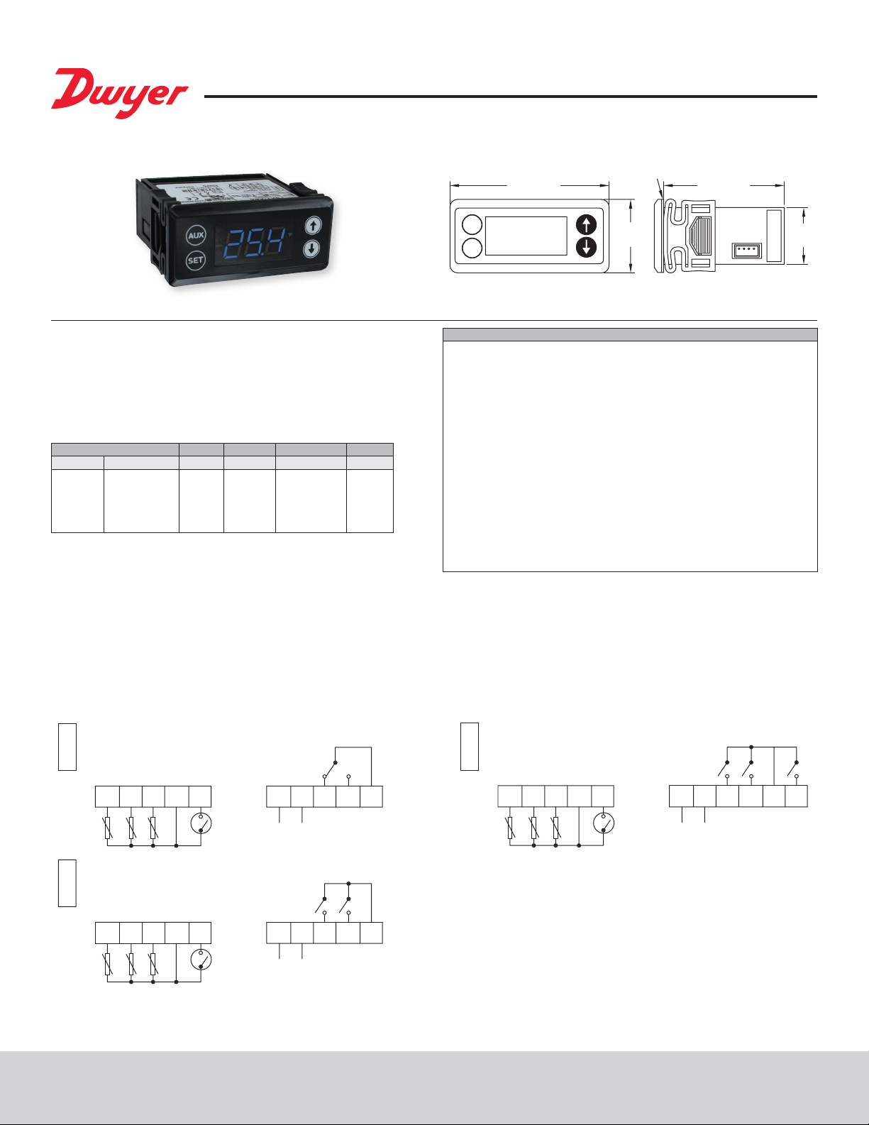
Series TSXT Digital Temperature Switch
REL2 REL1 COM REL3
GASKET
1.110
[28.3]
®
Specications - Installation and Operating Instructions
Bulletin T-TSXT
The Series TSXT Digital Temperature Switch is designed with many refrigeration
applications in mind. It accepts up to 3 temperature inputs, of either PTC or NTC
temperature probe types and can control the compressor, defrost, fan, alarm, and
light in a refrigeration system. These switches allow master/slave conguration to
synchronize the defrost cycle between different units. The Series TSXT programming
performed by the front keypad, the TS2-K programming key, or by RS485 module
communication. Standard features include capacitive buttons, real time clock, HACCP
alarm logging, temperature alarms, and password protected parameter settings.
MODEL CHART
Model Supply Power Outputs Model Supply Power Outputs
TSXT-211
TSXT-221
TSXT-231
TSXT-241
TSXT-212
TSXT-222
INSTALLATION
Note: Unit must be mounted away from vibration, impacts, water, and corrosive gases.
• Cut hole in panel 2.80 x 1.14 inches (71 x 29 mm).
• Use the included gasket, or apply silicone around the perimeter of the hole to prevent
leakage.
• Insert the unit into the hole in panel.
• Slide removable tting clips onto unit from back until secure to panel.
• Wire the unit per the wiring diagram on the product label or by gures below. Avoid
installing temperature probe and digital input wiring in the proximity of power cables.
115 VAC
230 VAC
12 VAC/VDC
24 VAC/VDC
115 VAC
230 VAC
1
1
1
1
2
2
TSXT-232
TSXT-242
TSXT-213
TSXT-223
TSXT-233
TSXT-243
12 VAC/VDC
24 VAC/VDC
115 VAC
230 VAC
12 VAC/VDC
24 VAC/VDC
2
2
3
3
3
3
3.110 [79.0]
AUX
SET
Panel cutout 2-51/64˝ x 1-9/64˝ (71 x 29 mm)
SPECIFICATIONS
Probe Range: PTC: -58 to 302°F (-50 to 150°C); NTC: -58 to 230°F (-50 to 110°C).
PTC (1000 Ω @ 25°C) or NTC (10 KΩ @ 25°C) thermistor.
Input:
Output: Relay 1: SPST relay rated 16 A @ 240 VAC resistive, 10 FLA, 60 LRA;
Relay 2: SPST relay rated 5 A @ 240 VAC resistive; Relay 3: SPST relay rated 8 A
@ 240 VAC resistive.
Horsepower Rating (HP): 1 HP (Relay 1).
Control Type: On/off with defrost options.
Power Requirements: 115 VAC, 230 VAC, 24 VAC/VDC, or 12 VAC/VDC.
Power Consumption: 3.6 VA @ 115/230 VAC; 1.5 VA @ 12/24 VAC/VDC.
Accuracy: ±1% FS.
Display: 3-digit, plus sign.
Resolution: 0.1°.
Memory Backup: Nonvolatile memory.
Ambient Operating Temperature: 32 to 131°F (0 to 55°C).
Storage Temperature: -4 to 176°F (-20 to 80°C).
115 and 230 V models: 7.2 oz (204 g); 12 and 24 V models: 4.8 oz (136 g).
Weight:
Front Panel Rating: IP65.
Agency Approvals: CE, cURus.
1.440
[36.5]
2.440 [62.0]
Wiring Diagram
Sd3 Sd2 Sd1 Com In Sd3 Sd2 Sd1 Com In
678910
POWER
SUPPLY
TSXT-XX1
TS2-K TS2-K
Sd3 Sd2 Sd1 Com In
1234 5 678910
1 relay output
TSXT-XX2
2 relay outputs
POWER
SUPPLY
DWYER INSTRUMENTS, INC.
REL1 COM
REL2 REL1 COM
TS2-K
1234 5 678910
POWER
SUPPLY
TSXT-XX3
3 relay outputs
111234 5
Page 2

Parameter Programming
Note: Set Point and the time programming are the only parameters accessible without
access code.
Activating and Deactivating Manual Defrost Cycle
Press and hold the AUX button for 2 seconds to activate defrosting. Repeat this
process to stop the defrosting. If a cool cycle is activated, the defrosting is disabled.
Set Point
• Press SET. Set Point value will appear on the display.
• Press SET again. The real value is shown on the display and can be modied with
the UP and DOWN arrows.
• Press SET to conrm any new values.
• Press SET and DOWN simultaneously to quit programming or wait one minute for
the display to automatically exit programming mode.
Real Time Clock
• Press SET. The Set Point value will appear on the display.
• Press the UP or DOWN arrow to change to Hour or Minute.
• Press SET to see the assigned value.
• Use the UP and DOWN arrows to set the desired value.
• Press and hold SET for 8 seconds to program value. The word “Pro” should appear
on the screen if the value has been programmed correctly.
• Press SET and DOWN simultaneously to exit or wait for the timeout.
Protected Parameters
• Press and hold SET for 8 seconds. The access code value 00 is shown on the
display.
• Using the UP and DOWN arrows, set the code (factory-set code is 00).
• Press SET to enter the code. If correct, the rst parameter label will be shown on
the display (SP).
• Use the UP and DOWN arrows to move to desired parameter and SET to view
parameter value.
• While viewing a parameter value, use the UP and DOWN arrows to modify parameter
value. Use SET to enter value and exit parameter.
• The display will blink when there is an error recording a parameter in memory or
when awaiting conrmation of a value.
• Press SET and DOWN simultaneously to quit programming or wait one minute to
automatically exit programming mode.
LED Indication and Display Messages
: Indicates if the load is connected. If continuous cool cycle is being
performed, this LED ashes (90% ON, 10% OFF). If the unit is waiting the
stopping time value stored in c0 to start a cool cycle the LED ashes (10%
ON, 90% OFF).
: Indicates if defrosting is active.
: Indicates an active alarm. The LED will ash if the alarm is cleared, but the
alarm condition persists.
: Indicates when fan control relay is active. Either H7 or H8 must be set to
one of the fan control modes (FAN or FAI).
HACCP: Indicates HACCP alarm recording feature is active.
Activating and Deactivating Cool Cycle
Press and hold the DOWN arrow for 8 seconds to activate a continuous cool cycle.
Repeat this process to stop the cool cycle. If defrosting is activated, the cool cycle is
disabled.
Fault Cycle
If the probe fails, the load is connected for the time set in c2 and then disconnected
for the time set in c3.
In case of memory error, the load is connected for 5 minutes and then disconnected
for 5 minutes.
On/Off Mode
This option is used to turn the control into an OFF or stand by mode, disabling the
display and outputs.
• Press and hold SET and DOWN for 8 seconds. The display will read OFF.
• Press and hold SET and DOWN for 8 seconds to return the control to normal
operation.
On/Off Light
The 2nd or 3rd relay can be congured as a lighting switch by setting the H7 or H8
parameter to Li. To activate or deactive the light relay, press and hold AUX and UP for
3 seconds.
Probe View
To view the probe not chosen in P5, press the SET and UP buttons.
HACCP
If this option is activated, the thermostat registers up to 5 high, low, and power loss
alarms. These alarms can be seen in the menu Registry of Alarms (HAC). To access
this menu, proceed to the parameters menu.
The rst value (nAt) that appears is the number of registered alarms. Next, the value
of the temperature (Adx) and the time of each alarm that exists (tdx) are displayed. For
the disconnection alarm, the temperature when returning the connection is registered,
as well as the time until the correct value is reached. (Probe<Set+A1-A0)
When the elapsed time is shown it will appear dxx (days). Pressing UP, hxx (Hours)
will be shown, and pressing UP again, nxx (Minutes) will be displayed. When located
over a temperature of alarm or time, pressing AUX + UP for 3 seconds, both recorded
data of the alarm (time and temperature value) are deleted.
In the HAC menu, pressing AUX + UP keys for 3 seconds, all the recorded alarm data
is deleted.
If an alarm or error occurs, the following messages will be shown and an internal
buzzer will sound.
The alarm can be cleared and buzzer silenced by pressing the SET and DOWN
buttons simultaneously. The alarm message will not be shown, but the alarm LED will
ash while the alarm condition persists.
Err = Memory error
ErP1 = Probe 1 error
ErP2 = Probe 2 error
ErP3 = Probe 3 error
Eri = Internal parameter error. In this case enter the factory default conguration, as
described in the Resetting to Factory Defaults section.
ALH = High temperature alarm
ALL = Low temperature alarm
ALE = External alarm
AEH = High temperature and external alarm
AEL = Low temperature and external alarm
ooo = Open probe error
- - - = Short circuit probe error
DON = Defrosting activated
DOF = Defrosting deactivated or cannot be done
CON = Continuous cold cycle activated
COF = Continuous cold cycle deactivated
-d- = Defrosting (when d5 set to -d-)
Setting Keyboard Code to Zero
• Turn unit off and back on. Press and hold SET for 8 seconds. Value 00 should ash
on the display.
• Set the code to 123 using the UP and DOWN arrows.
• Press SET to conrm the code. The code is now set to 00.
Resetting to Factory Defaults
• Access to parameter H0 as explained in parameter programming.
• Choose desired conguration.
• For Series TSXT-xx1: H0 is set to 0
• For Series TSXT-xx2: H0 is set to 1
• For Series TSXT-xx3: H0 is set to 2
• Press SET for 8 seconds, and the thermostat will be reset.
Page 3

List of Parameters
COn Description Units Range
SET
Set point
r0
Differential or hysteresis
r1
Minimum value for set point
r2
Maximum value for set point
r6
Fan operation
F0
Fan stoppage temperature
F1
Stop compressor & fan with door open
c0
Minimum compressor stoppage time
c1
Continuous cycle time
c2
ON time of fault cycle
c3
OFF time of fault cycle
c4
Minimum ON time of the compressor
c5
Minimum time between two connections of
the compressor
dEF Description Units Range
d0
Cool/Heat mode (ST13)
d0
Type of defrosting (ST23 & 33)
d1
Temperature at which defrosting will stop
d2
Maximum defrosting time
d3
First hour of day for defrosting
d4
Delay of rst defrosting
d5
Display on defrosting
d6
Display return limit
d7
Compressor drip time
d8
Interval between defrosting
d9
Fan works on defrosting
d10
Fan drip time
d11
Minimum defrosting time
d12
Fan/defrosting control probe
d14
Units to count the defrosting cycle
Pro Description Units Range
P0
Temperature scale
P1
Ambient probe 1 calibration
P2
Defrosting probe 2 calibration
P3
Product probe 3 calibration
P4
Decimal point
P5
Probe to display
P6
Probe 2 present
P7
Probe 3 present
ALA Description Units Range
A0
Fan and alarm differential
A1
Maximum alarm temperature
A2
Minimum alarm temperature
A3
Time validation open door or external alarm
A4
Time without alarm after defrosting
A5
Time without alarm after opening the door
A6
Time without alarm after connection
A7
Alarm verication time
A8
Probe for alarm
Ini Description Units Range
Hor
Hour
Min
Minutes
E0
Congure digital input
H0
Factory settings
H1
Master slave
H2
Keypad protection
H3
Delay time on connecting
H5
Keyboard code
H6
Type of probe
H7
Relay 2 setup
H8
Relay 3 setup
H10
HACCP activated
HdE
Next defrost time
MdE
Next defrost time
Note: For parameter settings described as h-m, the rst 2 digits represent hours, and
the third represents tens of minutes. (Example: 4.2 is 4 hours and 20 minutes).
Degrees
Degrees
Degrees
Degrees
Option
Degrees
Option
Minutes
h - m
Minutes
Minutes
Minutes
Minutes
Option
Option
Degrees
Minutes
h - m
Minutes
Option
Minutes
Minutes
h - m
Option
Minutes
Minutes
Option
Option
Option
Degrees
Degrees
Degrees
Option
Option
Option
Option
Degrees
Degrees
Degrees
Minutes
h - m
h - m
h - m
h - m
Option
Hours
Minutes
Option
Option
Option
Option
Seconds
Numeric
Option
Option
Option
Option
Hours
Minutes
r1 to r2
0.1 to 20
-99.9 to r2
r1 to 302
off/on/con
-99.9 to 302
no/yes/con/fan
0 to 240
0.0 to 18
0 to 999
0 to 999
0 to 240
0 to 240
re/in
re/in
-99.9 to 302
0 to 240
00.0 to 18.0
0 to 999
off/on/-d0 to 240
0 to 240
00.0 to 99.0
no/yes
0 to 240
0 to 240
sd1/sd2/sd3
rt/ct
°C/°F
-20.0 to 20.0
-20.0 to 20.0
-20.0 to 20.0
no/yes
sd1/sd2/sd3
no/yes
no/yes
0.1 to 20.0
0.1 to 99.9
0.1 to 99.9
0 to 999
0.0 to 18.0
0.0 to 18.0
0.0 to 18.0
0.0 to 18.0
sd1/sd2/sd3
0 to 23
0 to 59
all/AI/In/def/ndf
0 to 3
Mst/Slv
no/yes
0 to 240
0 to 999
PTC/NTC
lit/FAn/ALA/dEF/FAI
lit/FAn/ALA/dEF/FAI
no/yes
(only read)
(only read)
Parameter Descriptions
Compressor (COn)
SET = Working Set Point. Temperature the system trys to maintain. Variable
between r1 and r2.
r0 = Differential. When primary probe temperature >= Set+r0 Compressor ON
When primary probe temperature <= Set Compressor OFF
r6 = Fan operation on regulation.
Off = Fan does not connect on regulation.
On = Fan is always connected on regulation.
Con = Fan linked to compressor start-up.
(Fan ON if allowed by the temperature set in F0)
F0 = Fan temperature limit.
Direct mode. Relay selected as FAN. Fan OFF on regulation when probe temperature
set in d12 is >= F0. Fan ON on regulation, when temperature is =< F0 - A0.
Reverse mode. Relay selected as FAI. Fan OFF on regulation when probe
temperature set in d12 is < F0. Fan ON on regulation, when temperature is >= F0 + A0.
F1 = Stop compressor and Fan if door opened (Circuit closure between input
terminal 5 and common terminal 4).
No = the fan and compressor do not stop on regulation and continuous cycle when
opening the door.
Yes = the fan and compressor stop on regulation and continuous cycle when opening
the door.
Con = the compressor stop but the fan do not stop on regulation and continuous
cycle when opening the door.
Fan = the fan stop but the compressor do not stop on regulation and continuous
cycle when opening the door.
c0 = Minimum compressor stop time. Minimum time since compressor stops until
it is starts again.
c1 = Continuous cycle time. Duration of a continuous cold cycle.
c2 = ON time of fault cycle, when ambient probe is broken
c3 = OFF time of fault cycle, when ambient probe is broken
c4 = Minimum time since compressor starts until it stops.
c5 = Minimum time since compressor starts until it starts again.
Defrost (dEF)
d0 = Cool / Heat mode (ST13). re = cool; In = heat
d0 = Type of defrosting (ST23, ST33)
re = defrosting without connecting the compressor.
in = defrosting by connecting the compressor.
d1 = End of defrosting temperature. When this temperature is reached the defrosting
will end.
d2 = Maximum defrosting time. The defrosting will stop when this time is reached. If
it is zero there will be no defrosting.
d3 = First hour defrosting of the day. From 00:00 hours the rst defrosting is at d3
hours. Until this time no defrosting is performed.
d4 = Delay rst defrosting.
Time to carry out the rst defrosting if d3 = yes.
d5 = Display during the defrosting.
Off = the current temperature will be shown during defrosting.
On = the temperature at defrost beginning is frozen on display until the end of
defrosting and until the current temperature is equal or lower than the initial one, or
until d6 time elapses.
-d- = Label -d- is displayed during defrosting, until the end of defrosting and until the
current temperature is equal or lower than the initial one, or until d6 time elapses.
d6 = Display return limit. Maximum time before viewing the current temperature
again after defrosting.
d7 = Compressor drip time. Time since defrosting ends until the compressor can
be connected.
d8 = Interval between defrosting. Time between the start of a defrosting and the start
of the following one. If it is zero defrosting is not done automatically by time.
d9 = Fan operation during defrosting time. It determines if the fan is connected or
not during defrosting.
d10 = Fan drip time. Time since defrosting ends until fan can be connected.
d11 = Minimum Time duration defrosting. Once defrosting begins it stays at least
during this time
d12 = Fan & defrosting control probe.
sd1 = primary probe
sd2 = defrosting probe
sd3 = product probe
d14 = Units to count the defrosting cycle.
rt = according to the working time of the controller
ct = according to the working time of the compressor
Page 4

PROBES (Pr0)
P0 = Temperature scale. Select between °F and °C.
P1 = Primary probe calibration. Degrees shift of the primary probe display value.
P2 = Defrost probe calibration. Degrees shift of the defrosting probe display value.
P3 = Product probe calibration. Degrees shift of the product probe display value.
P4 = Decimal point
P5 = Probe to display. Probe to be viewed normally on the display.
P6 = Probe 2 present. If there is a probe 2 connected to thermostat.
P7 = Probe 3 present. If there is a probe 3 connected to thermostat.
ALARMS (ALA)
A0 = Fan & alarm differential.
This is the temperature difference between the on and off cycle of the alarms and fan.
A1 = Maximum alarm. High alarm ON at Set+A1. High alarm OFF at Set+A1-A0.
A2 = Minimum alarm. Low alarm ON at Set-A2. Low alarm OFF at Set-A2+A0.
A3 = Time validation open door or external alarm. If open door or external
alarm is maintained during this time, alarm will be indicated. (Depending on the E0
conguration of digital input).
A4 = Alarm exclusion time after defrosting. During the defrosting and this time after
it, temperature alarms will be ignored.
A5 = Alarm exclusion time after opening the door. While the door is open (if A5>0)
and time A5 after closing it, alarms will be ignored.
A6 = Alarm exclusion after connection. Until this time has elapsed since the
connection, temperature alarms will be ignored.
A7 = Temperature alarm time validation. Time since the alarm situation occurs, until
it is given.
A8 = Probe Alarm.
sd1 = primary probe
sd2 = defrosting probe
sd3 = product probe
INITIALIZATION (Ini)
Hor = Hour
Min = Minutes
E0 = Digital input conguration.
Off = Digital input disabled.
Al = External alarm. There is an alarm if input is short-circuited.
In = Door open if input is short-circuited.
def = Order to initiate a defrost if input is short-circuited.
ndf = No defrosting will be made if input is short-circuited.
H0 = Factory Conguration. Record Factory Conguration.
H1 = Master/Slave
H1 = Master. The thermostat issues defrosting orders to slave connected thermostats
through the digital input.
H1 = Slave. The thermostat performs defrosting ordered by the master connected to
its digital input.
In both cases the input must be E0=def.
H2 = Keyboard protection.
Yes = Keyboard protected. To modify Set, activate/de-activate defrosting and
activate/de-activate continuous cycle we have to enter the code and then quit. The
protection is removed momentarily. It is activated again 1 minute after the last key is
pressed.
No = Keyboard not protected.
H3 = Delay time on connecting. Until this time has elapsed since turning-on power,
the compressor will not start-up.
H5 = Input code to parameters. This code is set to 0 from factory.
H6 = Type of Probe. PTC or NTC.
H7 = Conguration Relay 2.
H8 = Conguration Relay 3. We can choose that it is light (Li), fan (Fan), alarm (ALA),
defrosting (dEF), or reverse fan (FAI).
H10 = HAACP activated. Yes or no.
HdE = Hours (HdE) portion of the time the defrost will begin at.
MdE = Minutes (MdE) portion of the time the defrost will begin at.
HACCP (HAC): (Only appears when H10 is set to yes).
nAt = # of recorded alarms.
Adx = Temperature of alarm point where x can be 1 through 5.
tdx = Time of alarm point where x can be 1 through 5.
dxx = days
hxx = hours
nxx = minutes
MAINTENANCE/REPAIR
Upon nal installation of the Series TSXT no routine maintenance is required. The
Series TSXT is not eld serviceable and should be returned if repair is needed. Field
repair should not be attempted and may void warranty.
CLEANING & REPAIR
Clean the surface of the display controller with a soft, damp cloth. Never use abrasive
detergents, petrol, alcohol, or solvents.
WARRANTY/RETURN
Refer to “Terms and Conditions of Sale” in our catalog and on our website. Contact
customer service to receive a return authorization number before shipping the product
back for repair. Be sure to include a brief description of the problem plus any additional
application notes.
©Copyright 2020 Dwyer Instruments, Inc. Printed in U.S.A. 5/20 FR# 444246-00 Rev. 1
DWYER INSTRUMENTS, INC.
 Loading...