

Page 1
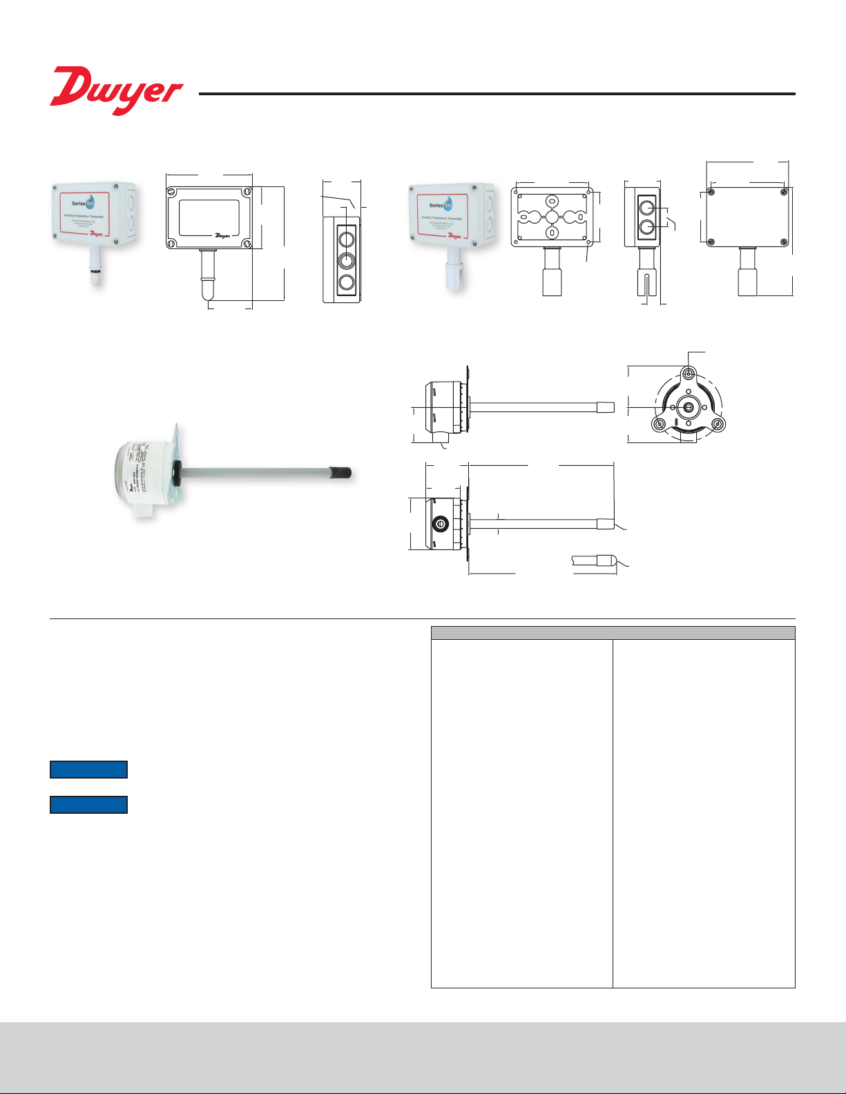
Series RHP Temperature/Humidity Transmitter
[172.09]
5-1/8
[21.83]
[67.07]
5-1/8
A
®
Specications - Installation and Operating Instructions
Bulletin E-90-RHP
Sintered lter version
[130.18]
2-41/64
3-45/64
[94.06]
6-25/32
[172.16]
Duct mount
55/64
[21.83]
2-1/4
[57.15]
OSA (outside air)
2-11/64
[55.17]
2-41/64
2-9/64
[54.37]
Ø3-11/64
[Ø80.57]
1/2 NPT
[67.03]
Ø35/64
[Ø13.89]
4-17/32
[115.09]
8-61/64
[227.30]
9-3/32 [231.13]
3-1/8
[79.38]
Ø3/16
[4.76]
MOUNTING
HOLES
TYP 4 PLCS
2-15/64
[56.75]
2-9/16
[64.96]
2-11/64
[55.12]
RHP-XDXX
RHP-XMXX
55/64
[79.38]
1-13/64
[30.56]
3-1/8
HOLES EQUALLY
4.115 [104.52] BC
4-17/32
[115.09]
[3] 3/16 [4.76]
SPACED ON
[130.18]
6-25/32
The Series RHP Humidity and Temperature Transmitter offers exibility, high
accuracy, long term stability, and reliable operation. Utilizing the duct and outside
air mounting congurations, the Series RHP monitors and controls humidity or both
humidity and temperature in a building energy management systems, commercial and
residential HVAC applications, clean rooms, museums, and climate chambers.
The Series RHP can be ordered with a single current or voltage output for humidity
or can be factory congured to have an additional current, voltage, or passive RTD or
thermistor temperature output. The optional display for the duct mount models allows
the user to read both the temperature and humidity simultaneously.
For
NOTICE
NOTICE
Failure to exercise good ESD practices may cause damage to the sensor.
best results, our model RHRS radiation shield is recommended
for sintered lter versions of the outside air transmitter.
Sensor is sensitive to Electro-Static Discharge (ESD). Follow
industry standard practice for control and protection against ESD.
SPECIFICATIONS
Relative Humidity Range: 0 to 100%
RH.
Temperature Range: -40 to 140°F
(-40 to 60°C).
Accuracy, RH: Model RHP2 ±2%
10-90% RH @ 25°C; Model RHP3 ±3%
20-80% RH @ 25°C.
Accuracy, Thermistor Temp Sensor:
±0.22°C @ 25°C (±0.4°F @ 77°F).
Accuracy, RTD Temp Sensor: DIN
Class B; ±0.3°C @ 0°C (±0.54°F @
32°F).
Accuracy, Solid State Temperature
Sensor: ±0.9°F @72°F (±0.3°C @ 25°C)
Hysteresis: ±1%.
Repeatability: ±0.1% typical.
Temperature Limits: -40 to 140°F
(-40 to 60°C).
Storage Temperature: -40 to 176°F
(-40 to 80°C).
Compensated Temperature Range: -4
to 140°F (-20 to 60°C).
4 to 20 mA Loop Powered Models:
Power requirements: 10 to 35 VDC;
Output signal: 4 to 20 mA, 2 channels for
humidity/solid state temperature, sensor
models (loop powered on RH).
0 to 5, 0 to 10 V Output Models: Power
requirements: 15 to 35 VDC or 15 to 29
VAC; Output signal: 0 to 5, 0 to 10 V @
5 mA max, 2 channels for humidity/solid
state temperature sensor models.
Response Time: 15 seconds.
Electrical Connections: Removable
screw terminal block.
Conduit Connection: Duct mount: 1/2˝
NPS; OSA: 1/2˝ (22.3 mm).
Drift: <1% RH/year.
RH Sensor: Capacitance polymer.
Temperature Sensor: Curves A,B,C, F:
Thermistor; Curves D,E: Platinum RTD
DIN 385; Curve 0: None; Curve 1,2:
Solid state band gap.
Housing Material: Duct mount: PBT;
OSA: Polycarbonate.
Enclosure Rating: Duct mount: NEMA
4X (IP65) for housing only; OSA: NEMA
4X (IP65).
Display: Duct mount only, Optional
2-line alpha numeric, 8 characters/line.
Display Resolution: RH: 0.1%; 0.1°F
(0.1°C).
Weight: Duct mount .616 (.3 kg) OSA 1
lb (.45 kg).
Agency Approvals: CE.
DWYER INSTRUMENTS, INC.
Page 2
INSTALLATION
1 2 3 4
1 2 3 4
RH RECEIVER
1 2 3 4 5
1 2 3 4 5
WARNING
Make sure all connections are in accordance with the job wiring diagram and in
accordance with national and local electrical codes. Use copper conductors only.
CAUTION
Avoid locations where severe shock or vibration, excessive moisture or corrosive
fumes are present. NEMA Type 4X (IP65) housings are intended for outdoor use
primarily to provide a degree of protection against wind-blown dust, rain, and hosedirected water.
Do not exceed ratings of this device, permanent damage not covered by warranty may
result. The 4 to 20 mA models are not designed for AC voltage operation.
Duct Mount
The transmitter should be mounted away from fans, corners, heating and cooling coils,
and other equipment that will effect the measurement of the relative humidity. It should
also be mounted in a location that receives adequate air ow for proper operation.
The transmitter should be mounted such that the conduit connection points down to
prevent moisture from entering.
1. Drill a 1˝ diameter hole into the duct at the desired location.
2. Insert the transmitter probe through the hole such that the mounting ange is
ush to the duct.
3. Use three #8 x 1/2˝ pan head sheet metal screws to attach the mounting ange to
the duct. Do not over tighten.
4. Remove top screw cover to access wiring terminals.
OSA (Outside Air)
The transmitter should be mounted under an eave, shield, or in an area that is out of
the elements or direct sunlight. The transmitter should be mounted with the sensor
pointing down to prevent water collection in the sensor cavity.
1. Remove the cover plugs from the face of the unit and the top cover.
2. Position the transmitter where it is to be mounted and mark the mounting holes in
each corner of the housing.
3. Drill or punch out marked locations.
4. Place the transmitter box over mounting holes on wall and align. Install wall mount
screws (not provided) in mounting holes.
5. Proceed with wiring according to Figure 1.
6. Replace cover and cover plugs on the face of the unit.
Disconnect power supply before installation to prevent electrical
shock and equipment damage.
Use electrostatic discharge precautions (e.g., use of wrist straps)
during installation and wiring to prevent equipment damage.
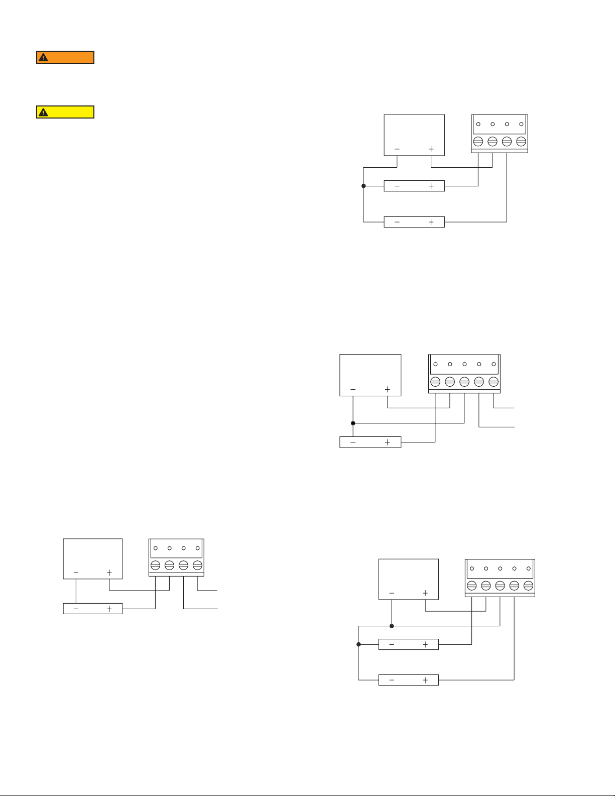
Dual 4 to 20 mA RH/Temperature Output Models
Dual 4 to 20 mA output units may be powered with a 10 to 35 VDC supply. The
following describes the proper wiring of these transmitters: The model RHP transmitter
with dual 4 to 20 mA output is designed as a two-wire 4 to 20 mA device with two
channels. The channels are common on the positive side of the current loop. Sensor
excitation power is derived from the RH channel, so power must always be applied to
that channel. If the temperature channel is not used, it can be left disconnected. Wire
as shown in Figure 2.
POWER
SUPPLY
RH RECEIVER
TEMP RECEIVER
Figure 2
Note: If the RH output is not required, wire the “-” terminal of the power supply to
terminal 1.
0 to 5 V and 0 to 10 V Output Models with Thermistor, RTD, or No Temperature
Sensor
The 0 to 5 V and 0 to 10 V output models may be powered with 15 to 35 VDC or 15
to 29 VAC. Note polarity when using DC power. The maximum load is 5 mA. Wire as
shown in Figure 3.
POWER
SUPPLY
TEMP
SENSOR
(IF PRESENT)
WIRING
Use maximum 18 AWG wire for wiring terminals. Refer to Figure 1 or Figure 2 for
wiring information. Terminal blocks are removable for ease of wiring.
4 to 20 mA Output Models with Thermistor, RTD or No Temperature Sensor
4 to 20 mA output units may be powered with a 10 to 35 VDC supply. (Wire as shown
in Figure 1).
POWER
SUPPLY
TEMP
SENSOR
(IF PRESENT)
RH RECEIVER
Figure 1
Figure 3
Dual 0 to 5 V and 0 to 10 V RH/Temperature Output Models
Dual 0 to 5 V and 0 to 10 V output units may be powered with 15 to 35 VDC or 15 to 29
VAC. Note polarity when using DC power. The channels are common on the negative
side. If desired, the RH or, temperature output may be used by itself. Wire as shown
in Figure 4.
POWER
SUPPLY
RH RECEIVER
TEMP RECEIVER
Figure 4
Page 3

DISPLAY
1
2
3
4
+
+
1
2
3
4
5
+
TEMP
SENSOR
TEMP
SENSOR
The temperature indicated on the display, if equipped with the LCD option, is eld
selectable via a jumper located on the circuit board. Position the jumper for °F or °C
according to Figure 5.
F
C
P4
°F/°C Selection Jumper
Figure 5
Note: The display will indicate temperature even if the unit does not have a temperature
output.
TROUBLESHOOTING
1. Verify that the unit is mounted in the correct position.
2. 4 to 20 mA Models:
Verify appropriate supply voltage. The transmitter requires a minimum of 10 and
a maximum of 35 VDC at its connection for proper operation. Choose a power
supply with a voltage and current rating which meets this requirement under all
operating conditions. If the power supply is unregulated, make sure voltage
remains within these limits under all power line conditions. Ripple on the supply
should not exceed 100 mV.
Loop Resistance – The maximum allowable loop resistance depends on the power
supply voltage. Maximum loop voltage drop must not reduce the transmitter voltage
below the 10 VDC minimum. Maximum loop resistance can be calculated with the
following equation. Vps is the power supply voltage.
MODEL CHART
Example RHP -2 D 1 A -LCD RHP-2D1A-LCD
Series RHP RH/temperature sensor transmitter
Accuracy 2
Housing
Type
RH Output 1
Temperature
Sensor
Option LCD LCD display; Blank; No options
3
5
D
M
O
S
R
2
3
2% accuracy
3% accuracy
5% accuracy
Duct mount with lter
Duct mount with HDPE lter
OSA (outside air)
OSA with sintered lter
Radiation shield
4 to 20 mA
0 to 10 V
0 to 5 VDC
A
10K @ 25°C thermistor Dwyer curve A
B
10K @ 25°C thermistor Dwyer curve B
C
3K @ 25°C thermistor Dwyer curve C
D
100 Ω RTD DIN 385
E
1K Ω RTD DIN 385
F
20KC 25°C thermistor curve F
0
No temperature output
1
4 to 20 mA solid state
2
0 to 10 V solid state
3
0 to 5 V
V
ps - 10.0
max =
Some receivers, particularly loop powered indicators, may maintain a xed loop
voltage to power the device. This voltage drop must also be subtracted from the power
supply voltage when calculating the voltage margin for the transmitter. The following
equation takes this into account. Vrec is the receiver xed voltage.
0 to 5 V and 0 to 10 V Output Models:
Verify appropriate supply voltage. The 0 to 5 V and 0 to 10 V output models require a
DC supply of 15 to 35 V or an AC supply of 15 to 29 V for proper operation maximum.
Maximum output load is 5 mA.
FIELD SENSOR REPLACEMENT
Replacement sensors are available for OSA sintered lter models (RHP-XSXX) and
duct mount models manufactured before February 2015. Sensor covers are also
available. Please contact Dwyer technical support for additional details.
R
Rmax =
V
ps - 10.0 - Vrec
20 mA
20 mA
Page 4

MAINTENANCE
Upon nal installation of the Series RHP Temperature/Humidity Transmitter and the
companion receiver, no routine maintenance is required. A periodic check of the
system calibration is recommended. The Series RHP is not eld serviceable and
should be returned if repair is needed (eld repair should not be attempted and may
void warranty). Be sure to include a brief description of the problem plus any relevant
application notes. Contact customer service to receive a return goods authorization
number before shipping.
This symbol indicates waste electrical products should not be disposed
of with household waste. Please recycle where facilities exist. Check with
your Local Authority or retailer for recycling advice.
©Copyright 2019 Dwyer Instruments, Inc. Printed in U.S.A. 4/19 FR# 443637-00 Rev. 10
DWYER INSTRUMENTS, INC.
 Loading...