

Page 1
BULLETIN F-55
["A"]
["B"]
["C"]
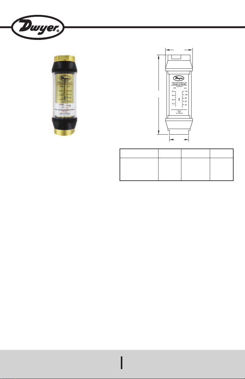
Series HF IN-LINE Flow Monitors
Specifications - Installation and Operating Instructions
Series HF Flow Monitors combine the simplicity of a
sharp edged orifice disk with a variable area flow
monitor to provide a low cost way to measure flow at
high pressures. These monitors are tubular, with all
internal wetted parts sealed within the body casing.
Running through the body is a tapered shaft which is
centered in the bore by pilot disks at each end.
Surrounding the shaft are a sharp-edged floating
orifice disk, a transfer magnet and return spring. The
disk and transfer magnet are held in the “no flow”
position by a biased return spring. As flow moves
through the monitor, it creates a differential pressure at
the orifice disk forcing the disk and transfer magnet
against the return spring. As flow increases, the
differential pressure at the disk increases, forcing the
disk and transfer magnet to move along the tapered
center shaft. As flow decreases, the biased return
spring forces the disk and transfer magnet down the
center shaft, returning to the “no flow” position. In metal
casing monitors, disk and magnet movement are not
visible so a magnet follower is located outside the body
casing, magnetically coupled to the internal transfer
magnet. As flow increases, motion of the internal
magnet moves the magnet follower outside the body
casing, under the scale.
Valve Size
1/8 NPT
1/4 to 1/2 NPT
3/4 to 1 NPT
1-1/4 to 1-1/2 NPT
2 NPT
SPECIFICATIONS
Service: Compatible gases or liquids.
Wetted Materials: Body: Aluminum, brass or 304 SS;
Seals: Buna-N or Fluoroelastomer; Magnet: PTFE
coated Alnico; Other internal parts: 304 SS.
Maximum Viscosity: 500 SSU.
Temperature Limits: HFA, HFL, HFB and HFS
Models: 240°F (116° C); HFH Models: 400°F (204°C).
Pressure Limits: HFA Models: 600 psig (41 bar);
HFL, HFB and HFH Models: 3500 psig (240 bar);
HFS Models: 6000 psig (413 bar).
Accuracy: ±2% FS over entire range.
Repeatability: ±1% of full scale.
Shipping Weight: 1/8 to 1/2˝ female NPT Models; 2
lb (0.9 kg); 3/4 to 1˝ female NPT Models: 3.5 lb (1.59
kg); 1-1/2˝ female NPT Models: 11 lb (5 kg); 2˝ female
NPT Models: 13.5 lb (6.12 kg).
“A”
Reference
1.25
1.875
2.375
3.500
3.500
“B”
Wrench Flats
0.875
1.250
1.750
2.250
2.250
“C”
Reference
4.813
6.562
7.125
10.125
12.625
DWYER INSTRUMENTS, INC.
Page 2

Aluminum body for air or other non-corrosive gases:
Wetted Parts: Aluminum, PTFE coated Alnico, 304 SS and Buna-N
Connection
Model
HFA-0-01
HFA-1-12
HFA-1-22
Aluminum body for oil based fluids:
Wetted Parts: Aluminum, PTFE coated Alnico, 304 SS and Buna-N
Model
HFL-2-05
HFL-4-25
Brass body for water based fluids (non-steam):
Wetted Parts: Brass, PTFE coated Alnico, 304 SS and Buna-N
Model
HFB-0-01
HFB-0-02
HFB-2-05
HFB-3-15
HFB-3-20
HFB-4-35
HFB-5-50
HFB-5-100
HFB-6-75
HFB-6-150
304 Stainless Steel body for high-pressure fluids:
Wetted Parts: 304 SS, Fluoroelastomer and PTFE
Model
HFS-0-01
HFS-2-02
HFS-2-10
Size
1/8˝ female NPT
1/4˝ female NPT
1/4˝ female NPT
Connection
Size
1/2˝ female NPT
1˝ female NPT
Connection
Size
1/8˝ female NPT
1/8˝ female NPT
1/2˝ female NPT
3/4˝ female NPT
3/4˝ female NPT
1˝ female NPT
1-1/2˝ female NPT
1-1/2˝ female NPT
2˝ female NPT
2˝ female NPT
Connection
Size
1/8˝ female NPT
1/2˝ female NPT
1/2˝ female NPT
Range, Air
SCFM
2-12
2-12
4-23
Range, GPM
Oil
0.5-5
2-25
Range, GPM
Water
0.05-1
0.2-2
0.5-5
2-15
2-20
4-40
5-50
10-100
8-75
20-150
Range, GPM
Water
0.05-1
0.2-2
0.5-10
Max. Pressure
Drop, PSID
3.32
3.32
3.61
Range, LPM
Oil
1-19
7.5-95
Range, LPM
Water
.19-3.8
.75-7.5
1-19
7.5-55
7.5-75
19-130
19-189
38-379
31-284
76-568
Range, LPM
Water
0.19-3.8
0.75-7.5
1.9-38
Max. Pressure
Drop, PSID
6.08
8.41
Max. Pressure
Drop, PSID
1.98
5.58
7.18
10.2
6.2
15.2
9.25
25.59
14.95
39.86
Max. Pressure
Drop, PSID
1.98
5.58
8.68
Brass Body High Temperature 400˚F for water based fluids:
Wetted Parts: Brass, PTFE coated Alnico, 304 SS and Fluoroelastomer
Model
HFH-2-05
HFH-2-10
HFH-4-35
READING THE MONITOR
Note the red reference line running 360° around the
white magnet follower. This line moves in direct
proportion to the movement of the internal orifice disk.
When fluid is flowing, the flow rate is read by aligning
the red reference line with the closest scale graduation.
SPECIFIC GRAVITY OR DENSITY EFFECT
Standard water monitors are calibrated with water and
oil monitors are calibrated with .873 S.G. oil. Flow
indication will read high for heavier fluids and low for
lighter fluids. A correction factor for other specific
gravities can be established using the following
formulas.
Connection
Size
1/2˝ female NPT
1/2˝ female NPT
1˝ female NPT
Range, GPM
Water
0.5-5
1-10
5-35
Range, LPM
Water
1-19
3.8-38
19-130
Max. Pressure
Drop, PSID
7.18
8.68
13.46
For Water Monitors use:
Actual = Observed Reading x 1.0
For Oil Monitors use:
Actual = Observed Reading x 0.873
VISCOSITY EFFECT
The Series HF Flow Monitor incorporates a unique
floating sharp-edged orifice disk which provides greater
operating stability and accuracy over wide ranging
viscosities up to 500 SSU.
√
√
S.G.
S.G.
Page 3

BASIC APPLICATION INFORMATION
The flow monitor can be installed directly in the fluid
line without flow straightening or special piping. They
are suitable for measuring the flow rate of most liquids
which do not contain particles larger than 74 microns.
1. The magnetic follower is sealed inside the Lexan
tube to allow use in areas where the unit might be
sprayed or washed with soap water.
2. Mount the monitor in a location allowing easy
access for reading and maintenance.
3. The monitor should not be located near hot pipes or
equipment which could damage the window tube
and/or scale.
4. Mount the monitor at least 1 ft (.3 m) from large
electric motors which can weaken or demagnetize
the internal magnet.
5. Aluminum should not be used for water.
WARNINGS AND PRECAUTIONS
1. These monitors are designed to operate in systems
that flow only in one direction, matching the
direction indicated by the arrow on the flow scale.
Operation in the reverse direction can damage the
monitor or other system components.
2. The window tube is made of polycarbonate which
can be safely cleaned with soap and water. many
other cleaning agents can damage this material,
causing discoloration or crazing. To check
compatibility, call General Electric’s polycarbonate
Compatibility Reference Line at 1(800)845-0600,
USA.
3. To maintain accuracy and repeatability, many
internal parts are precision machined and thus
require filtration or at least 74 micron or 200 mesh
screen.
4. All monitors are tested and calibrated using a light
hydraulic oil. Units are well drained, but some oil
residue may remain. Please check compatibility
with your fluid. Cleaning may be required before
use. See “Cleaning and Inspection.”
5. When installing aluminum or brass monitors onto
steel pipe, take caution not to over tighten
connections. Threads could strip if over tightened.
6. Aluminum and brass monitors should not be used in
systems where piping is not supported. Heavy
weight can cause the monitor to bend and
malfunction.
7. Do not exceed the maximum operating pressure or
temperature limit.
8. Pressure and flow surges can disengage the outer
magnet follower from the transfer magnet. If this
occurs, a shock suppressor should be used to avoid
repetitive malfunctions.
9. Caution should be used when using Teflon® thread
tape on joints. Leave at least 1/8˝ (3 mm) of
exposed pipe on the end.
10. These monitors use an internal transfer magnet in
their design. Because of this be aware of the
following:
a. Keep computer disks or tapes away from these
units.
b. If metal particles are flowing through this device,
a magnetic filter may be required.
BASIC INSTALLATION
Series HF Flow Monitors are installed in-line and are
direct reading. They can be mounted in a vertical or
horizontal position as long as flow is in the direction of
the arrow on the side. No straight pipe is required
before or after the monitor. If necessary, 90° elbows
can be installed on both ends without significant flow
variation. When installing, apply a small amount of pipe
thread sealant tape or pipe thread sealant to assure a
good seal. Locate filter, if used, in front of monitor and
in a location allowing easy access for routine
maintenance. Refer to Warnings and Precautions for
additional information.
FLUID FLOW IN REVERSE DIRECTION
These monitors will not allow flow in the reverse
direction, opposite to the arrow on the scale. In the
reverse direction unit will act like a leaky check valve.
If the application requires occasional reverse flow,
install a check valve in parallel with the monitor which
will force flow around the unit when reversed. This type
of check valve can be obtained from your local fluid
component distributor.
WARNING: Do not remove monitor from system
without proper and adequate safety measures if
fluid or gas is toxic, corrosive or flammable. Shut
down system and relieve pressure before removing
flow monitor from system.
DISASSEMBLY
Important: It is not necessary to remove the window
tube or window seals to clean the monitor. Note how
the unit is disassembled to aid in reassembly.
Warning - Shut down system and relieve pressure
before removing monitor from flow line.
1. Use a clean, dry cloth to remove all foreign matter
from exterior of monitor, especially around threaded
connections.
2. Remove monitor from flow line.
3. With the arrow on the scale pointing upward, secure
the unit in a vice using the flats on the inlet
connection. DO NOT apply wrench or vice to Lexan
tube.
4. Use a wrench on the flats provided on the outlet
connection and turn counter-clockwise to loosen.
Either port may come loose. Do not remove end
connection at this time.
5. Remove monitor from vice. Hold unit so the end
connection that has been loosened is on top.
Remove loose connection.
6. Tilt open end of monitor over a clean cloth to
expose inner cartridge. Remove inner cartridge
assembly from body casing. NOTE: Because the
transfer magnet is coupled magnetically to the
magnet follower, you will notice a light resistance
when removing the cartridge. If cartridge does not
slide out, insert a wooden dowl in opposite end of
monitor and push or rap lightly on dowel until
cartridge breaks free. IMPORTANT: If inner
cartridge does slide out freely, it may be a sign of
contamination. Locate and remove the source of
contamination before returning monitor to service or
the problem will reoccur. It may be necessary to
install finer filtration or a magnetic filter in the
system. The transfer magnet is a powerful Alnico
magnet. Keep it away from metal chips and filings.
They can be difficult to remove when reassembling
and will cause premature failure.
7. Examine inner cartridge assembly for
contamination. If the inner cartridge assembly has
no contamination and is working properly,
reassemble unit and return to service. If
contamination is found, proceed to Cleaning and
Inspection.
Page 4

CLEANING AND INSPECTION
1. Soak inner cartridge assembly in a suitable
cleaning solvent or soap and water. Caution:
When using a compressed air hose, wear proper
eye protection.
2. Remove parts from solvent. Use compressed air
and/or scrub lightly with a soft brush to remove any
remaining contaminants. Remove any magnetized
particles from transfer magnet.
3. Remove any contaminants from inside body
casing.
4. If inner cartridge assembly or body casing cannot
be cleaned, is scored, pitted or damaged beyond
repair, replace monitor.
5. Clean polycarbonate window with soap and water
or a compatible cleaning solvent.
6. Clean and inspect O-ring assemblies for nicks and
cuts. Replace as necessary.
7. After monitor is cleaned, reassemble in reverse
order of disassembly.
8. Clean and inspect monitor every six months.
Properly filtered monitor will provide years of
trouble free service. If unit is not properly protected
by a filter, damage and malfunction can occur.
Damage caused by excessive contamination is not
covered by warranty.
9. If the cartridge clip is removed or lost, a new clip
should be used. Cartridge retainer clips are Waldes
No. 5105-12H for 1/4˝ and 1/2˝ models, No. 510518H for 3/4˝, 1˝, 1-1/2˝, and 2˝ models.
RECOMMENDED FILTRATION
The manufacturer recommends system filtration of at
least a 74 micron filter or a 200 mesh screen. If
inadequate filtration has caused monitor failure, it will
normally fail in the open position. Some systems may
require a magnetic filter. Important: Monitor damage
caused by excessive contamination is not covered by
warranty.
STABILIZED CONTAMINATION
The goal of filtration is to create effective protection
from system contamination. Proper filtration stabilizes
contamination to allow fluid components to function
properly. A fluid system is considered stabilized when
“contamination in” equals “contamination out.” Proper
filtration must reduce initial contamination to a
stabilized level within an acceptable time period. The
entire system should be stabilized in time to prevent
premature wear or damage to monitor components.
CONTAMINATION SOURCES
Fresh Fluid - When new or fresh fluid is stored inside
holding tanks, the fluid may be contaminated with scale
or metal flakes from inside the tank. To prevent this
type of contamination, filter fresh fluid before adding to
the system.
New Machinery - When building new machines, a
certain amount of built-in contamination is
unavoidable. Typical built-in contamination might
include dust, dirt, chips, fibers, sand, flushing solutions,
moisture, weld splatters and pipe sealants. Flushing
the system before operation can reduce contamination
but cannot eliminate it entirely. Unless the system is
flushed at a high velocity some contamination will not
be dislodged until the system is in operation. System
contamination can cause fluid component malfunction.
Environmental Contamination - When performing
routine maintenance, the systems fluid is commonly
exposed to environmental contamination. Exercise
caution during routine maintenance to prevent this type
of contamination. Change breather filter and system air
filter regularly.
Self-Generated Contamination - Self-generated
contamination is a product of wear, cavitation, fluid
breakdown and corrosion. Systems that are carefully
flushed, maintained and have fresh fluids added,
mainly have self-generated contamination. In this
case, proper filtration can help prevent fluid component
malfunction.
COMPRESSIBILITY OF AIR AND GASES
Air and gases are extremely compressible. Gas
density increases as pressure increases. In most
cases, correction factors should be used to obtain
accurate readings. See correction factors below.
CALIBRATION
All standard Dwyer Instruments,Inc. air flow monitors
are calibrated for air with a specific gravity of 1.0 at 100
psig and 70°F (6.89 bar and 21.1°C). Monitors are
calibrated in SCFM, Standard Cubic Feet per Minute. A
standard cubic foot or air is defined as a cubic foot of
air at 70°F at atmospheric pressure, 14.7 PSI at sea
level. Since most industrial pneumatic systems
typically operate at 90-100 PSI, standard Dwyer
Instruments, Inc. Monitors are calibrated for inlet
conditions of 100 PSI at 70°F. When operating the
monitor at other pressures or temperatures, a
correction factor should be used to maintain the
original design accuracy of the monitor. When inlet
pressure of the monitor is at or near 100 PSI, the air
flow can be read directly from the monitor scale. When
pressure is other than 100 PSI, use the following
correction factor tables.
CORRECTION FACTORS FOR AIR AND GASES
SCFM (indicated) x (CF) = SCFM (actual)
1) x (f2) x (f3)
CF = (f
Note: It is not necessary to use all correction factors.
TABLE 1
(f1) PRESSURE CORRECTION FACTORS
14.7 + psig
f1=
––––––––––
√
114.7 psia
TABLE 2
(f2) TEMPERATURE CORRECTION FACTORS
√
√
530
––––––––
460 + °F
1
–––––––
Sp. Gr
.
f2=
TABLE 3
(f3) SPECIFIC GRAVITY CORRECTION FACTOR
f3=
INTERNAL GAGE PRESSURE
System pressure will vary from location to location in a
typical dynamic air or gas system. Because of this, it is
important that an accurate pressure gage be used to
determine flow conditions as close as possible to the
inlet port of the flow monitor.
©Copyright 2015 Dwyer Instruments, Inc Printed in U.S.A. 7/15 FR# 440843-00 Rev. 4
DWYER INSTRUMENTS, INC.
 Loading...