

Dwyer Instruments Series AP Diaphragm Operated Pressure Switches Installation and Operating Instructions
Page 1
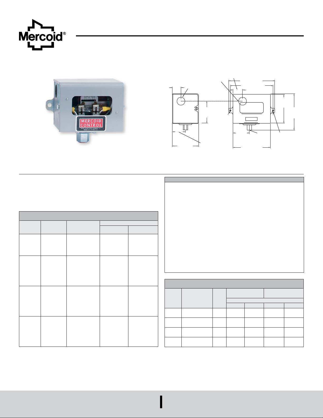
Series AP Diaphragm Operated Pressure Switches
[73.03]
]
1-1/16
By Dwyer
Specications - Installation and Operating Instructions
Bulletin O6S
Series AP Diaphragm Operated Pressure Switches are reliable, convenient,
compact, low-cost switches for instrument air or other low-pressure applications.
Visible set point and external adjustment add convenience. Used on air, noncorrosive
gas or liquid service compatible with wetted parts. These switches are available with
optional weather-proof and explosion-proof housings.
OPERATING RANGES - TYPE AP and AP-41
WITH MERCURY SWITCH (MM/W.C.), [BAR]
Deadband
Range
Number
33 -2
36 -2
37 -2
39 -2
Circuit Sufx
Number
-3
-88
-89
-153
-3
-26
-36
-88
-89
-153
-3
-26
-36
-88
-89
-153
-3
-26
-36
-88
-89
-153
Switch Action On
Press. Increase
SPST Opens
SPST Closes
SPST Closes
SPST Opens
SPST
SPST Opens
SPST Closes
SPST Closes
SPST Opens
SPST Closes
SPST Opens
SPST
SPST Opens
SPST Closes
SPST Closes
SPST Opens
SPST Closes
SPST Opens
SPST
SPST Opens
SPST Closes
SPST Closes
SPST Opens
SPST Closes
SPST Opens
SPST
Approx. Switch Deadband
Low High
8 in w.c. (205)
8 in w.c. (205)
3 in w.c. (80)
4 in w.c. (102)
5 in w.c. (127)
1.0 psig (0.07)
1.0 psig (0.07)
1.5 psig (0.10)
1.5 psig (0.10)
4 in w.c. (102)
6 in w.c. (152)
0.3 psig (0.02)
2.0 psig (0.14)
2.0 psig (0.14)
2.5 psig (0.17)
2.5 psig (0.17)
6 in w.c. (152)
8 in w.c. (205)
0.8 psig (0.06)
6 psig (0.41)
8 psig (0.55)
8 psig (0.55)
8 psig (0.55)
1.5 psig (0.10)
1.5 psig (0.10)
4 psig (0.28)
10 in w.c. (250)
10 in w.c. (250)
3 in w.c. (80)
4 in w.c. (102)
6 in w.c. (152)
2.0 psig (0.14)
2.0 psig (0.14)
2.5 psig (0.17)
2.5 psig (0.17)
8 in w.c. (205)
12 in w.c. (305)
0.5 psig (0.03)
3.0 psig [0.21]
3.0 psig [0.21]
3.5 psig [0.24]
3.5 psig [0.24]
12 in w.c. (305)
16 in w.c. (406)
1.5 psig [0.11]
16 psig (1.10)
17 psig (1.17)
20 psig (1.38)
20 psig (1.38)
3.0 psig (0.21)
3.0 psig (0.21)
10 psig (0.69)
15/16
[23.81]
SPECIFICATIONS
Wetted Materials: Nylon reinforced Buna-N and steel. PTFE and 316 SS
optional.
Temperature Limits: -30 to 150°F (-35 to 66°C).
Pressure Limit: See model chart.
Enclosure Rating: General purpose. Weatherproof and explosion-proof optional.
Switch Type: SPDT mercury switch or SPDT snap switch. Other switch types
available.
Electrical Rating: Mercury switch: 4A @ 120 VAC/DC, 2A @ 240 VAC/DC.
Snap switch: 15A @ 120 VAC, 8A @ 240VAC, 0.5A @ 120 VDC, 0.25A @ 240
VDC.
Electrical Connections: Screw terminal.
Conduit Connection: 7/8˝ (22.23 mm) hole for 1/2˝ (12.7 mm) conduit hub.
Process Connection: 1/4˝ female NPT.
Mounting Orientation: Vertical for mercury switch models, any position for snap
switch models.
Set Point Adjustment: External screw.
Weight: General purpose: 2 lb (0.9 kg).
Deadband: See model chart.
Agency Approvals: UL, CSA. For FM consult factory.
OPERATING RANGES - TYPE AP
WITH SNAP SWITCH (MM/W.C.), [BAR]
Range
Number
33 10˝ vac-50 in w.c.
36 1-20 psig (0.07-
37 1-30 psig
39 10-125 psig
7/8 [22.23]
CONDUIT HOLE
2-7/8
Adjustable
Range
(250 vac-1250)
1.4)
(0.07-2.1)
(0.7-8.6)
Ø7/8 [22.23]
KNOCK-OUT HOLE
2-13/32
[61.13]
SEALING WIRE
1-7/16
[36.52]
[26.99]
5-1/16 [128.69]
4-11/16 [119.36]
[2]Ø1/4
[6.35]
MOUNTING
HOLE WITH
Max.
Press.
psig
15
(1.0)
60
(4.1)
60
(4.1)
160
(11)
1-13/16
[46.05]
Single SPDT
Approx. Switch Deadband
Low High Low High
8 in w.c.
(205)
0.5 psig
(0.04)
0.75 psig
(0.05)
3 psig
(0.2)
1/4 NPT
4-1/8 [104.78]
10 in w.c.
(250)
1.5 psig
(0.11)
1.5 psig
(0.11)
7 psig
(.49)
3-1/8
[79.71]
ADJUSTMENT
SCREW WITH
SEALING WIRE
(2) SPDT Snap
Switches
4.5 in w.c.
(127)
0.75 psig
(0.05)
0.75 psig
(0.05)
1.25 psig
(0.09)
5 in w.c.
(127)
1.5 psig
(0.11)
1.5 psig
(0.11)
4 psig
(0.3)
4
[101.60
MERCOID
A DIVISION OF
DWYER INSTRUMENTS, INC.
Page 2
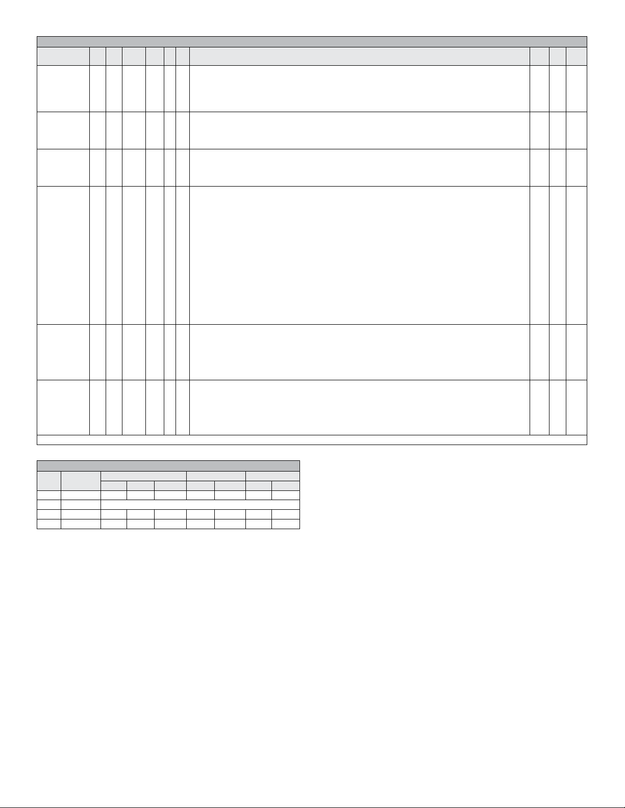
MODEL CHART
Example AP - - 153 - 36
Construction AP
Reset
Options
Housing
Options
Circuit
(Switching)
Options
Wetted
Materials
Adjustable
Pressure
Ranges
and Maximum
Operating
Pressures
*See chart below
AS
F
R
R
S
WT
W
H
-
-
-
-
-
-
-
70__
70__
80__
__
41
7021
8021
7041
8041
ULManual reset - operates on decrease automatically. NEMA-1 only.
2
3
26
36
88
89
153
( )
153
804
153
AP-153-36 Pressure Control, xed deadband, automatic reset, SPDT mercury switch, adjustable
range 1-20 psig (0.07-1.4 bar), maximum pressure 60 psig (4.1 bar)
General purpose enclosure, NEMA-1.
Low pressure steam switch, NEMA-1, range 34 only. Circuits, 2, 3, 26, 36, 153 only.
PTFE covered diaphragm, plated steel pressure port.
Factory mutual approved, NEMA-1, circuit 153 only. Range 37 only.
APF-153-37 or APF-7021-153-37 only.
Not available with circuit 88, 89 or snap switch type.
Manual reset - operates on increase automatically. NEMA-1 only.
Not available with circuit 88, 89 or snap switch type.
Less enclosure
Weather-proof enclosure, NEMA-4.
Weather-proof enclosure with condensate drain, NEMA-2, 3R.
Explosion-proof enclosure, NEMA-7, 9, Class I Group, C & D; Class II Group E, F & G.
SPST mercury switch, Electrical code P* - opens on pressure increase.
SPST mercury switch, Electrical code P*- closes on pressure increase.
SPST mercury switch, Electircal code R* - closes on pressure increase.
Not available with range 33.
SPST mercury switch, Electrical code R* - opens on pressure increase.
Not available with range 33.
SPST magnetic mercury switch, Electrical code T* - closes on pressure increase.
SPST magnetic mercury switch, Electrical code T* - opens on pressure increase.
SPDT mercury switch, Electrical code S*.
Other circuits available, consult factory.
SPDT snap acting switch, rated 15A at 120 VAC, 8A at 240 VAC, 0.5A at 120 VDC, 0.25A at 240 VDC, 3/4
hp at 120 VAC, 1 hp at 240 VAC.
DPDT: 2 each SPDT snap acting switches, rated 5A at 120/240 VAC, 5A at 30 VDC resistive
SPDT snap acting switch, rated 15A at 120 VAC, 8A at 240 VAC, 4A at 480 VAC, 6A at 24 VDC resistive,
0.5A at 120 VDC, 0.25A at 240 VAC, 3/4 hp at 120 VAC, 1.5 hp at 240 VAC.
Mercury switch type. Plated steel pressure port, Buna-N diaphragm.
Mercury switch type. 316 SS pressure port, PTFE diaphragm.
Snap switch type. Plated steel pressure port, Buna-N diaphragm.
Snap switch type. Plated steel pressure port, Buna-N diaphragm.
Snap switch type, 316 SS pressure port, PTFE diaphragm.
Snap switch type, 316 SS pressure port, PTFE diaphragm.
33
Adjustable range 10˝ wc VAC -50 in w.c (250 mm VAC to 1250 mm w.c.), maximum pressure 15 psig.
Adjustable range 1-15 psig (0.07 to bar), AS only, maximum pressure 30 psig (2.1 bar), maximum
34
temperature 275°F (135°C) psig.
36
Adjustable range 1-20 psig (0.07-1.4 bar), maximum pressure 60 psig (4.1 bar).
37
Adjustable range 1-30 psig (0.07-2.1 bar), maximum pressure 60 psig (4.1 bar).
39
Adjustable range 10-125 psig (0.7-8.6 bar), maximum pressure 160 psig (11 bar).
UL
UL
UL FM
UL
UL
UL
UL
UL
UL
UL
UL
UL
UL
UL
UL
UL
UL
UL
UL
UL
UL
UL
UL
UL
UL
CSA
CSA
CSA
CSA
CSA
CSA
CSA
CSA
CSA
CSA
CSA
CSA
CSA
CSA
CSA
CSA
CSA
CSA
CSA
CSA
CSA
CSA
CSA
ELECTRICAL RATING MERCURY SWITCH
Circuit
Code
Sufx No.
P -2, -3 10A 5A 3A 10A 5A 3/4 1/3
R -26, -36 17A AT 120/240/277 VAC, Resistive balance same as above.
S -153 4A 2A NA 4A 2A 1/8 NA
T -88,-89 0.5A 0.25A NA 0.125A 0.125A
AC Capacity DC Capacity Horsepower
120V 240V 440V 120V 240V AC DC
Page 3

Type AP and AP-41 with Sufx No’s.
-153, -2, -3, -26, 36, -88, -89
Type AP and AP-41with Sufx No’s.
153, -2, -3, -26, 36, -88, -89
OPERATION
A variation in control pressure causes the diaphragm to actuate the hermetically
sealed mercury switch to open or close the electrical contact.
APPLICATION
Type AP with sufx numbers -153, -2, -3, -26, -36, -88, -89 are for use with mediums
not injurious to steel, silver solder or Fairprene diaphragm.
Type AP-41 with sufx numbers -153, -2, -3, -26, -36, -88, -89 are for use with mediums
not injurious to 316 SS and PTFE.
MOUNTING
Install control rmly in a LEVEL POSITION on a panel or smooth wall surface by means
of two mounting ears. Where pipe mounting is desired, control may be connected by
means of the 1/4˝ I.P.S. connection. Do not mount control by twisting the case;
use a wrench on the square part of the 4˝ bottom pipe connection. To level, sight
across the two cover screws or check the lower end of the glass opening in the cover
to see that instrument is lined up horizontally.
WIRING
Wire in accordance with local electrical codes or equipment manufacturers’
instructions. See nameplate attached to inside of control case for terminal markings
and electrical rating. Do not overload. Do not oil any parts. Do not tamper with switch
wires. Position of these wires is essential for proper operation. Tampering with these
wires will void warranty.
OPERATION
A variation in control pressure causes the diaphragm to actuate the snap action switch.
APPLICATIONS
Type AP, APH, APW, APWT with sufx numbers 7021-153 or 8021-153 are for use
with mediums not injurious to steel, silver solder, Nylon/Buna-N diaphragm.
Type AP, APH, APW, APWT with sufx numbers 7041-153 or 8041-153 are for use
with mediums not injurious to 316 SS and PTFE covered diaphragm.
MOUNTING
Mount in any position.
Type AP (general purpose) can be installed on a panel or smooth surface using the
two mounting ears or the 4˝ NPT bottom connection. Do not mount by twisting the
case; use a wrench on the square part of the 4˝ bottom pipe connection.
Type APW-NEMA 3 (weather-resistant): 4˝ male NPT bottom connection.
Type APWT-NEMA 4 (water-tight): 4˝ male NPT bottom connection.
Type APH (explosion-proof ): 4˝ male NPT bottom connection. Or use mounting
bracket No. PP-135-95
WIRING
Wire in accordance with the national Electrical code and local regulations. Observe
wiring diagram inside enclosure and details below for type No. and electrical rating.
Where control is connected directly into the load circuit, it must be wired into hot side
of line. Do not overload. Do not oil any parts.
ON HI
COMMON
ON LO ON LO ON LO
ON HI ON HI
COMMON COMMON
-804 - DP-DT-153 - SP-DT
All types single-pole, double-throw (-153) or
double-pole, double throw (-804) operation
Page 4

ADJUSTMENTS
Turn adjustment screw “A” (see above) until pointer on dial indicates desired operations
pressure.
ELECTRICAL RATING
SERIES 7021-153 & 7041-153 - SPDT
SERIES 8021-153 & 8041-153 - SPDT 15A max. 120V AC; 8A MAX. 240V AC 15A
max. 120V AC; 8A 240V AC; O.5A max. 120V DC; 0.25A 240V DC 4A 480V AC 3/4
Hp. 120V AC. 1 Hp. 240V AC 0.5A 120V DC; .25A 240V AC. 3/4 Hp. 120V AC; 12 Hp.
240V AC. SERIES 7021-804 & 7041-804 ( 2 SPDT) 5A 120/240 AC - 30V DC resistive
MERCOID
Printed in U.S.A. 6/20 FR# 442111-00 Rev. 2©Copyright 2020 Dwyer Instruments, Inc.
A DIVISION OF
DWYER INSTRUMENTS, INC.
 Loading...