

Dwyer Instruments Series 2-5000 Minihelic II Specifications-installation And Operating Instructions
Page 1
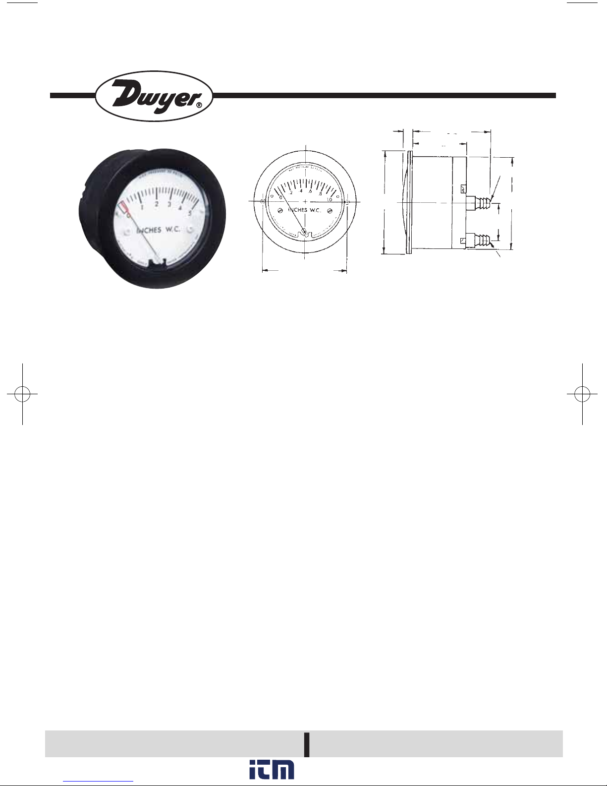
2.33 [59.18]
MOUNTING HOLES
*1-3/64 [26.59] for optional 1/8⬙ NPT connections
HI PRESSURE
1-3/32*
[27.78]
2-19/32
[65.88]
LO PRESSURE
2-3/16 [55.56]
1-17/32 [38.89]
1/4
[6.35]
2-29/32
[73.82]
Dimensions, Series 2-5000 Minihelic®II Gage.
SPECIFICATIONS
Dimensions: 2-29/32″ (73.82 mm) x
2- 7/16″ (61.93 mm).
Weight: 6 oz. [170 gr].
Rated Total Pressure: 50 psig (3.445 bar)
surge; 30 psig (2.067 bar) continuous to
either pressure connection.
Ambient Temperature Range: 20°F to
120°F (- 6.7°C to 49°C).
Accuracy: ± 5% of full scale at 70°F
(21.1°C).
Connections: standard, barbed for 3/16″
I.D. tubing; optional,1/8″ NPT(M).
Housing: glass-filled nylon, polycarbonate
lens.
Finish: black
Standard Accessories: (2) 4-40 x 1-5/8″
mounting studs, (2) 4-40 hex nuts,
(1) .050″ hex allen wrench, (1) panel
mounting bracket.
Series 2-5000 Minihelic®II Differential
Pressure Gages have clean design, small
size, low cost and sufficient accuracy for all
but the most demanding applications. With
housing molded from mineral- and glass-filled
nylon and a lens molded from polycarbonate,
this gage will withstand rough use and exposure, as well as high total pressure up to 30
psig [2.067 bar].Over-pressure is accommodated by a blow-out membrane molded in
conjunction with the diaphragm.
INSTALLATION
1. Select a location free from excessive vibration and where ambient temperature will be
between 20°F to 120°F (-6.7°C to 49°C).
Sensing lines may be any length necessary
without affecting accuracy. However, long
runs of tubing will dampen readings slightly
and cause a minor increase in response time.
If pulsing pressure or vibration cause excessive pointer oscillation, please contact factory
for ways to provide additional damping.
2. This gage is calibrated and zeroed in the
vertical position at the factory. If the gage is
used in any other position, it must be rezeroed each time the position is changed.
Gages with ranges under 5 inches w.c.(1.24
kPa), or the equivalent, should be used only in
the vertical position unless special calibration
was specified when ordering.
Bulletin A-36
Series 2-5000 Minihelic®II
Differential Pressure Gage
Specifications: Installation & Operating Instructions
DWYER INSTRUMENTS, INC.
Phone: 219/879-8000 www.dwyer-inst.com
P.O. BOX 373 • MICHIGAN CITY, IN 46361, U.S.A. Fax: 219/872-9057
e-mail: info@dwyer-inst.com
CAUTION:
Use only with air or compatible noncorrosive gases.
www. .com
information@itm.com1.800.561.8187
Page 2
3. To surface-mount the gage, drill two
5/32″ [3.97 mm] holes on a horizontal
line, 2-1/3″ [59.26 mm] apart for
mounting screws. Next, drill two
7/16” [11.11 mm] holes 1-1/32″
[26.19 mm] apart on a vertical line for
pressure connections. Install mounting studs in back of the gage, insert
through holes in the panel, and secure
with hex nuts provided. Be careful not
to block the slotted hole near the
right-hand mounting hole. This provides a path for pressure relief in the
event of over-pressurization.
4. To panel-mount gage, cut a 2-5/8″
diameter hole. Install the mounting
studs in the back of gage, position
gage in the panel, and place bracket
over the studs. Thread hex nuts over
studs and tighten.
5. After installation, the gage may
need to be zeroed before placing in
operation. If re-zeroing is required,
firmly hold the case of gage with one
hand and unscrew the front cover with
the palm of the other hand in a counterclockwise direction. If difficult to
loosen, place a small sheet of rubber
between the cover and the palm of the
hand. Zero-adjust screw is located
behind the scale at the pair marked
“zero.” Use the hex allen wrench
supplied and adjust until pointer is
on zero. This must be done with
both pressure connections vented
to atmosphere and the gage oriented in the final mounting position.
Replace cover.
6. To measure positive pressure,
connect tubing to port marked “HI”
and vent “LO” port to atmosphere.
For negative pressure (vacuum),
connect to port marked “LO” and
vent “HI” port to atmosphere. For
differential pressure, connect higher
pressure to port marked “HI” and
lower to “LO” port. If gage is supplied with 1/8″ NPT connections, be
careful not to over-tighten fittings to
avoid damage to the gage.
CALIBRATION CHECK
Select a second gage or manometer
of known accuracy and in an appropriate range. Use short lengths of
rubber or vinyl tubing to connect
the high-pressure side of the
Minihelic®II gage and the test gage
to two legs of a tee. Very slowly,
apply pressure through the third leg.
Allow enough time for pressure
to equalize throughout the system
and for fluid to drain. if a manometer
is being used. Compare readings.
If the gage being tested exceeds
rated accuracy, it should be
returned to the factory for recalibration.
MAINTENANCE
No lubrication or periodic servicing
is required. Keep case exterior and
cover clean. Occasionally, disconnect pressure lines to vent both
sides of the gage to atmosphere
and re-zero per paragraph 5.
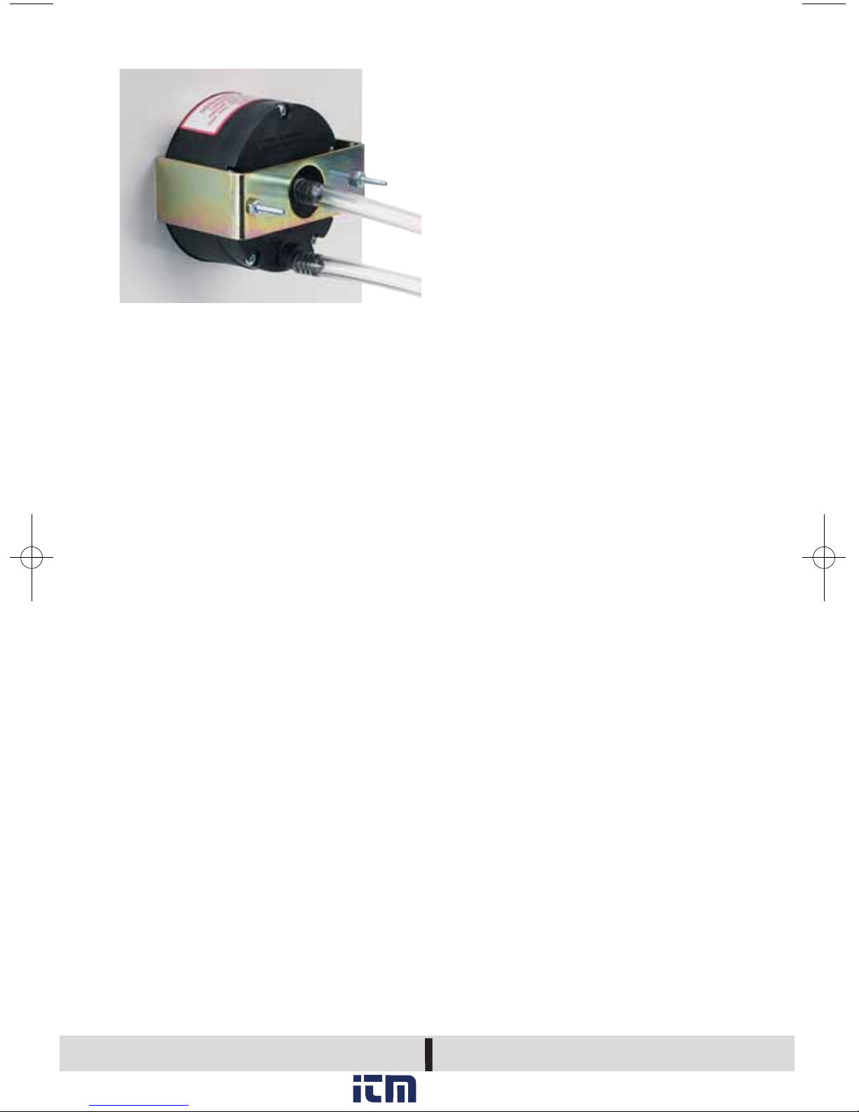
PANEL MOUNTED INSTALLATION
Bulletin A-36
©Copyright 2009 Dwyer Instruments, Inc Printed in U.S.A. 7/09 FR# 14-440434-00 Rev. 2
DWYER INSTRUMENTS, INC.
Phone: 219/879-8000 www.dwyer-inst.com
P.O. BOX 373 • MICHIGAN CITY, IN 46361, U.S.A. Fax: 219/872-9057
e-mail: info@dwyer-inst.com
www. .com
information@itm.com1.800.561.8187
 Loading...