

Page 1
RUBBER PRESSURE RELIEF PLUG
17/32
SERIES 2000
E
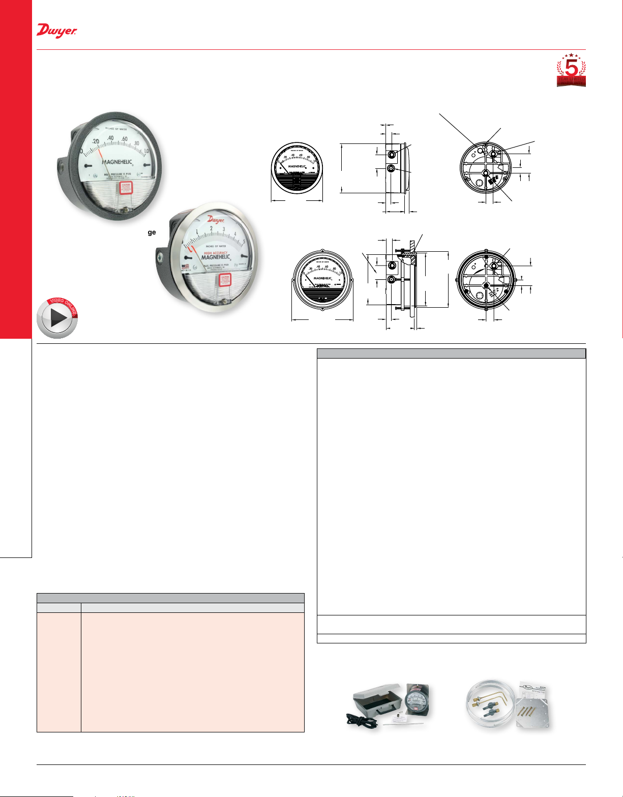
MAGNEHELIC® DIFFERENTIAL PRESSURE GAGES
Indicate Positive, Negative or Differential, Accurate within 1%
PRESSURE
.025 [.64] SPACE CREATED BY 3 SPACER
PADS WHEN SURFACE MOUNTED.
DO NOT OBSTRUCT. PROVIDES PATH
FOR RELIEF OF OVERPRESSURE.
Ø4-3/4
[120.65]
®
Standard Magnehelic
E
O
D
I
V
O
N
L
I
N
Select the Series 2000 Magnehelic® Differential Pressure Gages for a versatile low
differential pressure gage with a wide choice of 81 models and 27 options to choose
from. Using Dwyer’s simple, frictionless Magnehelic
indicates air or non-corrosive gas pressures--either positive, negative (vacuum) or
differential. The design resists shock, vibration, over-pressures and is weatherproof
to IP67.
Select the –HA High Accuracy Magnehelic
of full-scale. Also included with the –HA option at no extra cost are a mirrored scale
overlay and a 6 point calibration certicate.
FEATURES/BENEFITS
• Easy to read gage through undistorted plastic face permits viewing from far away
• Patented design provides quick response to pressure changes means no delay in
assessing critical situations
• Durable and rugged housing and high-quality components combine to provide long-
Differential Pressure Gages
service life and minimized down-time
• High accuracy option is twice as accurate as the standard Magnehelic
APPLICATIONS
• Filter monitoring
• Air velocity with Dwyer pitot tube
• Blower vacuum monitoring
• Fan pressure indication
• Duct, room or building pressures
• Clean room positive pressure indication
ACCESSORIES
Model Description
A-432
Portable kit; combine carrying case with any Magnehelic
standard range, except high pressure connection. Includes 9 ft (2.7
m) of 3/16˝ ID rubber tubing, standhang bracket and terminal tube
with holder
A-605
Air lter gage accessory kit; adapts any standard Magnehelic
for use as an air lter gage. Includes aluminum surface mounting
bracket with screws, two 5 ft (1.5 m) lengths of 1/4˝ aluminum tubing,
two static pressure tips and two molded plastic vent valves, integral
A-605B
compression ttings on both tips and valves
Air lter gage accessory kit; air lter kit with two plastic open/close
valves, two 4˝ steel static tips, plastic tubing and mounting ange
A-605C
Air lter gage accessory kit; air lter kit with two plastic open/close
valves, two plastic static tips, plastic tubing and mounting ange
DWYER INSTRUMENTS, INC. | 20
gage
High Accuracy Magnehelic® gage
Note: Shown with optional -SS bezel
®
gage option for an accuracy within 1%
®
gage movement, it quickly
®
gage
®
gage of
®
gage
ø5-1/2
[139.70]
MOUNTING RING
SPECIFICATIONS
Service: Air and non-combustible, compatible gases (natural gas option available).
Note: May be used with hydrogen. Order a Buna-N diaphragm. Pressures must be
less than 35 psi.
Wetted Materials: Consult factory.
Housing: Die cast aluminum case and bezel, with acrylic cover. Exterior nish is
coated gray to withstand 168 hour salt spray corrosion test.
Accuracy: ±2% (-HA model ±1) of FS (±3% (-HA ±1.5%) on -0, -100PA, -125PA,
-10MM and ±4% (-HA ±2%) on -00, -60PA, -6MM ranges), throughout range at 70°F
(21.1°C).
Pressure Limits: -20 in Hg to 15 psig (-0.677 to 1.034 bar); MP option: 35 psig
(2.41 bar); HP option: 80 psig (5.52 bar).
Enclosure Rating: IP67.
Overpressure: Relief plug opens at approximately 25 psig (1.72 bar), standard
gages only.u
Temperature Limits: 20 to 140°F* (-6.67 to 60°C). -20°F (-28°C) with low
temperature option.
Size: 4˝ (101.6 mm) diameter dial face.
Mounting Orientation: Diaphragm in vertical position. Consult factory for other
position orientations.
Process Connections: 1/8˝ female NPT duplicate high and low pressure taps - one
pair side and one pair back.
Weight: 1 lb 2 oz (510 g), MP & HP 2 lb 2 oz (963 g).
Standard Accessories: Two 1/8˝ NPT plugs for duplicate pressure taps, two
1/8˝ pipe thread to rubber tubing adapter, and three ush mounting adapters with
screws. (Mounting and snap ring retainer substituted for three adapters in MP & HP
gage accessories.)
Agency Approvals: Meets the technical requirements of EU Directive 2011/65/EU
(RoHS II). Note: -SP models not RoHS approved.
Note: For applications with high cycle rate within gage total pressure rating, next
higher rating is recommended. See Medium and High pressure options.
*Low temperature models available as special options.
1-1/4 [31.75]
Ø4-1/2
[114.3]
15/32 [11.91]
1-11/16 [42.86]
1-1/4
[31.75]
WILL UNSEAT ITSELF WHEN GAGE
IS OVERPRESSURIZED
17/32
[13.49]
1/8 FEMALE
NPT HIGH
PRESSURE
CONNECTION
1/8 FEMALE
NPT LOW
PRESSURE
CONNECTION
7/16 [11.11]
ø4-3/4 [120.65]
PANEL CUTOUT
ø5
[127]
ø4-47/64
[120.27]
3/16
[4.76]
[17.46]
ø4-1/2
[114.3]
15/32
[11.91]
[13.49]
2-17/32
[64.29]
A-432 A-605
uOver Protection Note: See page 21 (Series 2000)
[3] 6-32 X 3/16 [4.76] DEEP
HOLES EQUALLY SPACED ON
A Ø4-1/8 [104.78] BOLT CIRCLE
FOR PANEL MOUNTING
1/2
[12.70]
1/8 FEMALE NPT LOW
11/16
PRESSURE CONNECTION
[17.46]
1/8 FEMALE NPT
HIGH PRESSURE
CONNECTION
1/2
[12.70]
11/16
1/8 FEMALE
NPT LOW
PRESSURE
CONNECTION
1/8 FEMALE NPT
HIGH PRESSURE
CONNECTION
1-3/4
[44.45]
1-3/4
[44.45]
YEAR LIMITED
WARRANTY
Page 2
SERIES 2000
PRESSURE
MAGNEHELIC® DIFFERENTIAL PRESSURE GAGES
Indicate Positive, Negative or Differential, Accurate within 1%
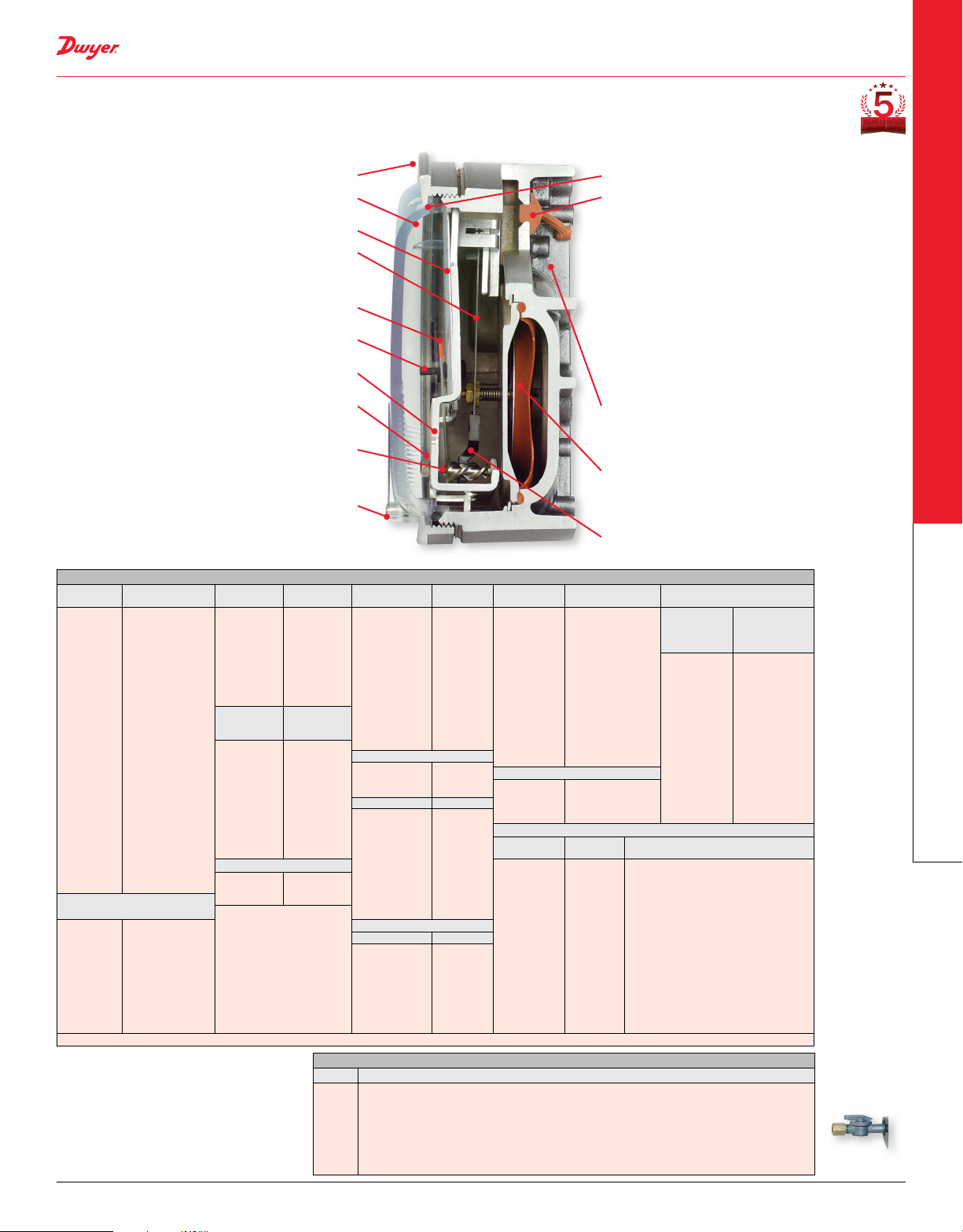
Bezel provides ange for ush mounting in panel.
Clear plastic face is highly resistant to breakage. Provides
undistorted viewing of pointer and scale.
Precision litho-printed scale is acc ur at e an d ea sy to rea d.
Calibrated range spring is at spring steel. Small
amplitude of motion assures consistency and long life. It
reacts to pressure on diaphragm. Live length adjustable for
calibration.
Red tipped pointer of heat treated aluminum tubing is easy
to see. It is rigidly mounted on the helix shaft.
Pointer stops of molded rubber prevent pointer over-travel
without damage.
“Wishbone” assembly provides mounting for helix, helix
bearings and pointer shaft.
Jeweled bearings are shock-resistant mounted; provide
virtually friction-free motion for helix. Motion damped with
high viscosity silicone uid.
Helix is precision made from an alloy of high magnetic
permeability. Mounted in jeweled bearings, it turns freely,
following the magnetic eld to move the pointer across the
scale.
Zero adjustment screw is conveniently located in the
plastic cover, and is accessible without removing cover.
O-r ing seal provides pressure tightness.
YEAR LIMITED
WARRANTY
O-ring seal for cover assures pressure integrity of case.
OVERPRESSURE PROTECTION
Blowout plug is comprised of a rubber plug on the rear
which functions as a relief valve by unseating and venting
the gage interior when over pressure reaches approximately
25 psig (1.7 bar). To provide a free path for pressure relief,
there are four spacer pads which maintain 0.023˝ clearance
when gage is surface mounted. Do not obstruct the gap
created by these pads.
The blowout plug is not used on models above 180˝ of
water pressure, medium or high pressure models, or on
gages which require an elastomer other than silicone for the
diaphragm.
The blowout plug should not be used as a system
overpressure c ontrol. High supply pressures may still
cause the gage to fail due to over pressurization, resulting
in property damage or serious injury. Good engineering
practices should be utilized to prevent your system from
exceeding the ratings of any component.
Die cast aluminum case is precision made and iriditedipped to withstand 168 hour salt spray corrosion test.
Exter ior nished in baked dark gray hammerloid. One case
size is used for all standard pressure options, and for both
surface and ush mounting.
Silicone rubber diaphragm with integrally molded O-ring
is supported by front and rear plates. It is locked and
sealed in position with a sealing plate and retaining ring.
Diaphragm motion is restricted to prevent damage due to
overpressures.
Samar ium Cobalt magnet mounted at one end of range
spring rotates helix without mechanical linkages.
MODEL CHART
Model
2000-00N†••
2000-00†••
2000-0†•
2001
2002
2003
2004
2005
2006
2008
2010
2012
2015
2020
2025
2030
2040
2050
2060
2080
2100
2120
2150
2160
2180*
2250*
Zero Center Ranges
2300-00†••
2300-0†•
2301
2302
2304
2310
2320
2330
†These ranges calibrated for vertical scale position • Accuracy ±3% •• Accuracy ±4% *MP option standard **HP option standard
VELOCITY AND VOLUMETRIC FLOW UNITS
Scales are available on the Magnehelic
gage that read in velocity units (FPM, m /s)
or volumetr ic ow units (SCFM, m3/s, m3/h).
Stocked velocity units with dual range scales
in inches w.c. and feet per minute are shown
above. For other ranges contact the factory.
When ordering volumetric ow scales please
specif y the maximum ow rate and its
corresponding pressure.
Example: 0.5 in w.c. = 16,000 CFM.
Range,
Inches of Water Model
.05-0-.2
0-.25
0-.50
0-1.0
0-2.0
0-3.0
0-4.0
0-5.0
0-6.0
0-8.0
0-10
0-12
0-15
0-20
0-25
0-30
0-40
0-50
0-60
0-80
0-100
0-120
0-150
0-160
0-180
0-250
0.125-0-0.125
.25-0-.25
.5-0-.5
1-0-1
2-0-2
5-0-5
10-0-10
15-0-15
2201
2202
2203
2204
2205
2210*
2215*
2220*
2230**
Model
2000-15CM
2000-20CM
2000-25CM
2000-50CM
2000-80CM
2000-100CM
2000-150CM
2000-200CM
2000-250CM
2000-300CM
Zero Center Ranges
2300-4CM
2300-10CM
2300-30CM
Range,
PSI Model
0-1
0-2
0-3
0-4
0-5
0-10
0-15
0-20
0-30
Range, CM
of Water
0-15
0-20
0-25
0-50
0-80
0-100
0-150
0-200
0-250
0-300
2-0-2
5-0-5
15-0-15
®
2000-6MM†••
2000-10MM†•
2000-15MM
2000-25MM
2000-30MM
2000-50MM
2000-80MM
2000-100MM
2000-125MM
2000-150MM
2000-200MM
2000-250MM
2000-300MM
Zero Center Ranges
2300-6MM†••
2300-10MM†•
2300-20MM†•
Model Range, Pa
2000-60NPA†••
2000-30PA†••
2000-60PA†••
2000-100PA†•
2000-125PA†•
2000-250PA
2000-300PA
2000-500PA
2000-750PA
2000-1000PA
Zero Center Ranges
Model Range, Pa
2300-60PA†••
2300-100PA†•
2300-120PA
2300-200PA
2300-250PA
2300-300PA
2300-500PA
2300-1000PA
ACCESSORIES
Model Description
A-321
Safety relief valve
A-448
3-piece magnet kit for mounting Magnehelic
A-135
Rubber gasket for panel mounting
A-401
Plastic carry case
A-310A
3-way vent valves. In applications where pressure is continuous and the Magnehelic® gage
is connected by metal or plastic tubing which cannot be easily removed, we suggest using
Dwyer A-310A vent valves to connect gage. Pressure can then be removed to check or
re-zero the gage
Range, MM
of Water Model
0-6
0-10
0-15
0-25
0-30
0-50
0-80
0-100
0-125
0-150
0-200
0-250
0-300
3-0-3
5-0-5
10-0-10
10-0-50
0-30
0-60
0-100
0-125
0-250
0-300
0-500
0-750
0-1000
30-0-30
50-0-50
60-0-60
100-0-100
125-0-125
150-0-150
250-0-250
500-0-500
2000-0.5KPA
2000-1KPA
2000-1.5KPA
2000-2KPA
2000-2.5KPA
2000-3KPA
2000-4KPA
2000-5KPA
2000-8KPA
2000-10KPA
2000-15KPA
2000-20KPA
2000-25KPA
2000-30KPA
Zero Center Ranges
2300-1KPA
2300-2KPA
2300-2.5KPA
2300-3KPA
Dual Scale English/Metric Models
Model
2000-00D†••
2000-0D†•
2001D
2002D
2003D
2004D
2005D
2006D
2008D
2010D
2015D
2020D
2025D
2050D
2060D
Range,
kPa
0-0.5
0-1
0-1.5
0-2
0-2.5
0-3
0-4
0-5
0-8
0-10
0-15
0-20
0-25
0-30
.5-0-.5
1-0-1
1.25-0-1.25
1.5-0-1.5
Range,
in w.c.
0-.25
0-0.5
0-1.0
0-2.0
0-3.0
0-4.0
0-5.0
0-6.0
0-8.0
0-10
0-15
0-20
0-25
0-50
0-60
®
gage directly to magnetic surface
Dual Scale Air Velocity Units
For use with pitot tube
Model
2000-00AV†••
2000-0AV†•
2001AV
2002AV
2005AV
2010AV
Range,
Pa or kPa
0-62 Pa
0-125 Pa
0-250 Pa
0-500 Pa
0-750 Pa
0-1.0 kPa
0-1.25 kPa
0-1.5 kPa
0-2.0 kPa
0-2.5 kPa
0-3.7 kPa
0-5 kPa
0-6.2 kPa
0-12.4 kPa
0-15 kPa
DWYER INSTRUMENTS, INC. |
Range, in w.c./
Velocity F.P.M.
0-.25/
300-2000
0-.50/
500-2800
0-1.0/
500-4000
0-2.0/
1000-5600
0-5.0/
2000-8800
0-10/
2000-12500
Differential Pressure Gages
A-310A
21
Page 3

HIGH ACCURACY MAGNEHELIC® DIFFERENTIAL PRESSURE GAGE
E
PRESSURE
Twice as accurate as the
standard Magnehelic
®
gage
Mirrored scale overlay
eliminates parallax error
E
O
D
I
V
O
N
L
I
N
IP67 weatherproof housing
6-point calibration
Optional brushed SS bezel
certicate included
OPTIONS - HIGH ACCURACY MAGNEHELIC® GAGE
To order
add sufx: Description
-HA
High accuracy Magnehelic
within 1% and weatherproof. Also includes
mirrored scale overlay and a six point
calibration certicate
-SS
Corrosion resistant brushed 304 stainless
steel bezel
Accuracy Specications: See page 20 (Series 2000)
YEAR LIMITED
WARRANTY
®
gage. Accuracy
ADDITIONAL GAGE OPTIONS
LED set point indicator Adjustable signal ag
Differential Pressure Gages
Transparent overlay Mirrored scale overlay
Integrated mounting plate
OPTIONS - OTHER OPTIONAL BEZELS
To order add sufx: Description
-CB
Chrome bezel option: A chrome plated aluminum bezel for an
aesthetically pleasing nish when mounting on metal surfaces
such as control panels.
-SB
Stainless steel bezel option: 304 stainless steel electro polished
Ra 16 nished bezel.
-SS
Corrosion resistant brushed 304 stainless steel bezel
OPTIONS - LED SET POINT INDICATOR
To order add sufx: Description
-SP Bright red LED on right scale shows when set point is reached.
Field adjustable from gage face, unit operates on 12-24
VDC. Set point indicator option comes with medium pressure
(MP) bezel.
Note: 4-13/16˝ hole for ush mounting.
OPTIONS - ADJUSTABLE SIGNAL FLAG
To order add sufx: Description
-ASF Integral with plastic gage cover. Available for most models
except those with medium or high pressure construction. Can be
ordered with gage or separate.
OPTIONS - TRANSPARENT OVERLAYS
To order add sufx: Description
-G
-R
-Y
Green (to highlight and emphasize critical pressures)
Red (to highlight and emphasize critical pressures)
Yellow (to highlight and emphasize critical pressures)
OPTIONS - MIRRORED SCALE OVERLAY
To order add sufx: Description
-M A mirrored scale overlay is also available to assist in reducing
parallax error.
OPTIONS - INTEGRATED MOUNTING PLATE
To order add sufx: Description
-AHU1
-AHU2
Furnished with attached surface mounting plate
Furnished with attached surface mounting plate and including
A-481 installer kit (2 plastic static pressure tips and 7´of
PVC tubing)
OPTIONS - FOR HIGH STATE PRESSURE APPLICATIONS
To order add sufx: Description
-HP
-MP
High pressure option: for pressures to 80 psig
Medium pressure option: for pressures to 35 psig
OPTIONS
To order add sufx: Description
-FC
-LT
-NIST
DWYER INSTRUMENTS, INC. | 22
Factory calibration certicate
Low temperatures to -20°F (-28°C)
NIST traceable calibration certicate
Page 4

MAGNEHELIC® GAGE MOUNTING ACCESSORIES
E
Pressure
reference
port
PRESSURE
A-610
E
O
D
I
V
O
N
L
I
N
A-286
A-369
A-300
A single case size is used for most models of Magnehelic® gages. They can be
ush or surface mounted with standard hardware supplied. Complete mounting and
connection ttings plus instructions are furnished with each instrument. A 4-9/16˝ hole
is required for ush panel mounting.
Flush mounting is easily accomplished with the new A-300 Flush Mounting bracket.
This bracket provides a solution to quickly and conveniently ush mount the
Magnehelic
panel doors.
The A-368 is a simple bracket for quickly surface mounting the Magnehelic
After securing the Magnehelic
at surface.
The A-369 allows the Magnehelic
®
gage. The A-300 is ideal for mounting the Magnehelic® gage on control
®
®
gage to the A-368 bracket, mount the bracket on any
®
gage to be easily carried to locations where
gage.
pressure readings need to be taken. The A-369 can stand on its own or hang on a
nail or hook.
A-464
A-368
ACCESSORIES
Model Description
A-610
Pipe mounting kit for installing on 1-1/4˝ to 2˝ horizontal or vertical pipe
A-286
Magnehelic
A-369
Stand-hang bracket, aluminum, for Magnehelic
Flush mounting bracket
A-300
Flush mount kit for Magnehelic
A-464
Surface mounting plate, aluminum, for Magnehelic
A-368
Mounting bracket, ush mount for Magnehelic
A-299
®
gage panel mounting ange
®
gage
®
gage
®
gage
®
gage, bracket is then
surface mounted, steel with gray hammerloid epoxy nish
Surface mounting bracket, use with medium pressure (-MP) or high
A-371
pressure (-HP) models only
A-299
A-371
 Loading...