

Page 1
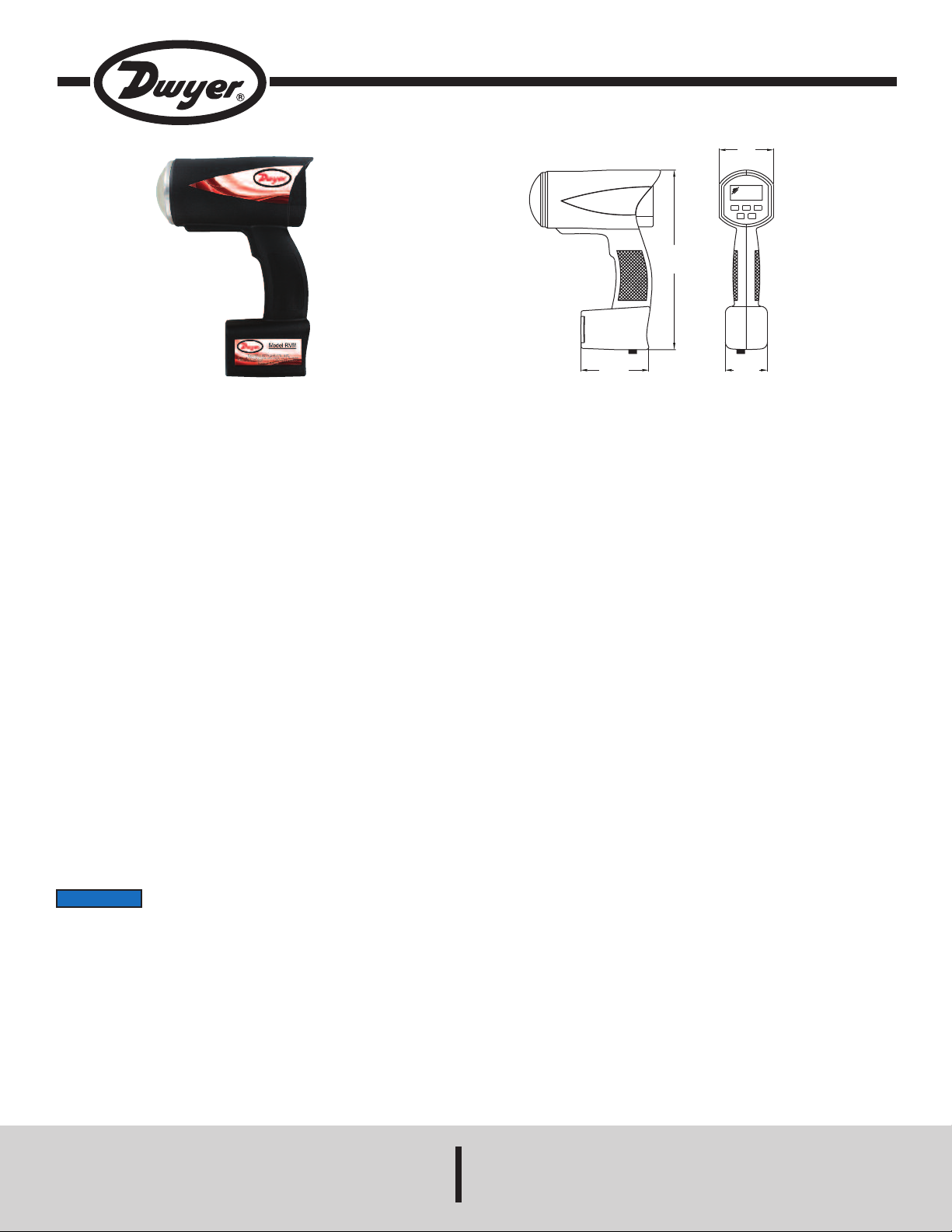
Model RVM Portable Radar Wave Velocity Meter
3
[76.3]
1
0
[
250.8]
2-1/4
[59.0]
3
-3/4
[
95.0]
M
ODE
MENU
S
EL
P
WR
RCL
Specifications - Installation and Operating Instructions
Bulletin TE-RVM
he Model RVM Portable Radar Wave Velocity Meter uses Doppler Radar
T
technology to accurately measure surface velocity of open channel flow. The
“point-and-shoot” design along with automatic vertical angle compensation
provides easy to use operation. Model RVM also has user-adjustable horizontal
angle compensation of 5° increments to further reduce measurement error. Flow
elocity can be measured bi-directionally with user-selectable directional modes
v
flows away, towards, or both in direction). Model RVM features a backlit LCD that
(
ndicates flow velocity in feet per second or meters per second. Model RVM
i
includes the meter, rechargeable batteries, 12 VDC car charger, and a rugged
case.
*Wireless Guidelines in Accordance with FCC:
Changes not expressly approved by Dwyer Instruments, Inc. could void the user's
authority to operate the equipment.
This product complies with FCC OET Bulletin 65 radiation exposure limits set forth
for an uncontrolled environment.
Pursuant to FCC 15.21 of the FCC rules, changes not expressly approved by
Dwyer Instruments, Inc. might cause harmful interference and void the FCC
authorization to operate this product.
Canadian Government Guidelines:
Operation is subject to the following two conditions: (1) This device may not cause
harmful interference and (2) this device must accept any interference received,
including interference that may cause undesired operation.
INFORMATION TO THE USER
Power Output: 7 mW nominal.
Power Density: ≤ 1 m/W/cm.
Operating Frequency: 24.150 GHz nominal (K band).
Beam Width: 12° nominal.
Polarization: Linear.
Power Density: ≤ 1 m/W/cm.
SPECIFICATIONS
ervice: Water.
S
ange: 0.1 to 43 FPS (0.3 to 13 m/s).
R
isplay: Single-line, 5-digit, backlit LCD.
D
Accuracy: ±5%.
Power Requirements: 6.1 to 8 VDC, (6) 1.2 V rechargeable AA NiMH batteries,
installed and functional, user replaceable (12 VDC lighter plug power cable
included).
ower Consumption: 0.18 A max.
P
Serial Communications: RS232.
Temperature Limits: -22 to 158°F (-30 to 70°C).
Enclosure Rating: IP55.
Humidity Limit: 90% RH @ 98.6°F (37°C).
Enclosure Material: ABS polycarbonate blend.
Angle Compensation:
Vertical: automatic via tilt sensor;
Horizontal: adjustable from 0 to 60° in 5° increments for cosine angle error.
Weight: 2.1 lb (907 g).
Agency Approvals: *FCC compliance.
NOTICE
• Do not over voltage the radar velocity meter - it can damage
the unit! See notes.
• If battery replacement is necessary, all 6 batteries should be replaced with new
batteries even if only one cell is suspected to be defective.
• Use rechargeable Nickel-Metal-Hydride batteries only.
• Model RVM is designed to operate off of conventional +12 VDC (+10.8 to +16.5
VDC) from the power cable. In addition, it is also designed to operate at 7.2 VDC
from the internal batteries. Over voltage to the power cables or incorrect batteries
can cause damage.
• Do not expose Model RVM to excessive moisture. Never submerge the device. If
the device should accidently get submerged, remove the batteries immediately.
• Do not drop Model RVM on hard surfaces since damage could occur.
DWYER INSTRUMENTS, INC.
Phone: 219/879-8000 www.dwyer-inst.com
P.O. BOX 373 • MICHIGAN CITY, INDIANA 46360, U.S.A. Fax: 219/872-9057 e-mail: info@dwyermail.com
Page 2
ntroduction
I
odel RVM Portable Radar Velocity Meter is a hand-held surface velocity radar gun
M
pecifically designed to measure the surface velocity of water. Features such as
s
Recall allow the review of previous measurements. Other features are selectable
through the menu option.
he radar gun features a tilt sensor system, which internally compensates for the
T
osine angle effect of the vertical (pitch-down) angle of the gun to the target. It is not
c
ecessary to manually set the tilt sensor.
n
Battery Charging
Model RVM is designed to operate off of six (6) rechargeable Nickel-Metal-Hydride
batteries (or off the DC power cord). Upon initial procurement, the batteries will need
o be charged. Once the batteries have been fully charged, and if Model RVM is not
t
sed for 3-4 weeks, recharging of the batteries before use will be necessary in order
u
o get the full run time.
t
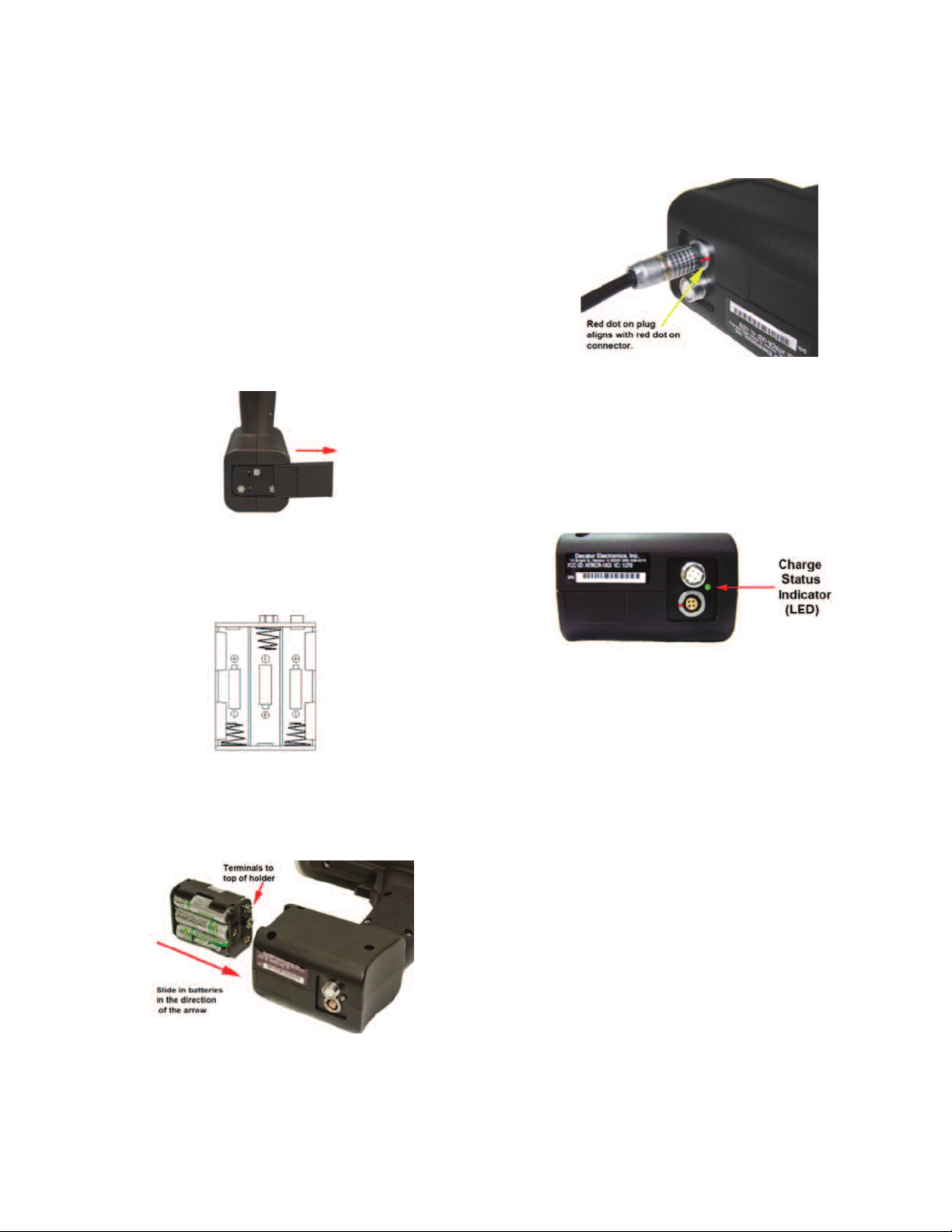
Removing the Battery Holder
The battery holder is located inside the handle of Model RVM and is accessed by
means of a sliding door. When first received, the holder will have batteries pre-
nstalled. To remove the battery holder, slide the battery cover to the right until the
i
attery holder is released as shown in Figure 1. The door can be completely removed
b
rom the slide.
f
igure 1
F
harging the Batteries
C
he power cable included with Model RVM can be used to either power the unit
T
irectly from a vehicle receptacle or to charge the batteries. Once the batteries have
d
been properly installed into the holder and inserted into the handle, plug the power
cord into the power connector at the base of the handle by aligning the red dot on the
power cord’s plug with the red dot on the connector. Failure to align the plug with the
onnector properly will result in damage to the pins of the jack. Reference Figure 4 for
c
roper alignment.
p
igure 4
F
Charge Status Indicator (LED)
The status of the charge can be determined by the Charge Status Indicator LED
located on the bottom of the handle (See Figure 5). The LED indication status is
escribed below.
d
ast blinking green light = checking battery condition
F
Medium blinking green light = charging battery
Solid green light = charged
Solid red light = charging error
Battery Installation
Insert the batteries into the battery holder following the polarity guide that is on the
inside of the battery holder (Figure 2). Notice that the negative side of each battery
goes to the spring contacts of the holder.
Figure 2
Inserting the Battery Holder
The battery holder is designed so that it can only make contact with the power
connections inside the meter if the battery holder is slid into the handle properly. The
battery holder has positive and negative terminals which need to be inserted into the
meter with the terminals located at the top as shown in Figure 3.
Figure 5
The normal charging sequence is fast blink for 60 seconds, medium blink until
batteries are fully charged (approximately 2 hours for fully discharged batteries) and
solid green once batteries are charged.
Model RVM can be left to charge indefinitely. The charging circuit will automatically
shut off once charging is complete. The unit must be OFF or the batteries will not
charge. You can not operate the unit and charge the batteries at the same time. Best
performance from the batteries is obtained when recharged at temperature between
50ºF (10ºC) and 113ºF (45ºC). Recharging outside of the specified temperature range
may result in reduced battery life or incomplete charging.
Battery Run Time
The length of time Model RVM can operate between recharges depends upon several
factors including the milliamp hour (mAh) capacity of the batteries, age of the
batteries, and how the unit is used. Generally a set of 6 new 2500 mAh batteries fully
charged should run for approximately 1 week between recharges given normal use.
Auto Power Off
If no key press is detected, the Model RVM will automatically power off after 5 minutes
in order to conserve battery life.
Replacing Batteries
When replacing the batteries, only use rechargeable Nickel-Metal-Hydride batteries
and replace ALL the batteries at the same time, even if only one battery is suspected
to be failing.
Figure 3
Once the batteries have been properly loaded into the holder and the holder has been
inserted into the handle of the gun, then the door can be put back in place and slid
closed. If the holder has been placed incorrectly into the handle, the door cannot be
put back in place and closed.
Connecting the Power Cord
If you choose to run off the power cord instead of the internal batteries, connect the
power cord to the receptacle on the bottom of Model RVM being sure to properly align
the plug on the power cord to the connector on the bottom of the unit’s handle. Model
RVM will automatically switch from the internal batteries to the power cord for power
when the unit is turned on.
Page 3

lug in the Power Cord
P
lug the radar’s power cord into any vehicle’s 12 V charging receptacle. If a separate
P
attery pack is being used as a power source, plug Model RVM’s power cord into the
b
attery pack’s receptacle.
b
Control Panel Functions
The operation of Model RVM is controlled by the five-button key pad, shown in Figure
.
6
Figure 6
MENU - The MENU button lets you view the options you can change. Repeatedly
pressing the MENU button advances through the programmable features.
SEL - The select (SEL) button lets you choose the settings in each of the mode
ptions. To change a mode option, press the SEL button.
o
WR - The PWR button turns the radar on and off. When first powered on, Model
P
RVM will display the screen shown in Figure 6. When you power the unit off, the word
OFF will appear in the display and the unit will power down.
RCL - When the RCL button is pressed, the unit will start the process of taking a
reading.
MODE - The MODE button lets you change the resolution of the display. You can
choose to have the speed displayed in 10ths or 100ths.
igure 8
F
Mounting Configurations
The radar velocity meter is designed for hand-held operation. Optionally, it can be
ounted to a standard camera tripod.
m
perating Modes
O
The MENU and SEL buttons on the Model RVM Radar Velocity Meter control panel
let you review and change programmable settings. The radar gun will remember the
settings that were last set when it is turned off and will power up with them. The menu
options are listed in Table 1.
ow Default Setting
etters
L
isplayed
D
bL
COS
U
A
escripton
D
Backlight
Horizontal Angle
ompensation
C
Unit of Measure
Vertical Angle
etting
S
election
S
On/Off (Default = Off)
0 to 60° in 5° increments
Default - 0°)
(
USA = FPS
EUr = M/S
(Default = M/S)
Not adjustable
verification only
H
s Displayed
i
bL
COS
U
A
Display
The 5 large digits (88888) display the speed, figure 7. Resolution is determined by the
placement of the decimal point. The icons indicate the status.
Figure 7
When first turned on, the Model RVM performs a segment check of the display to
show that all segments and icons are working. The following icons will appear at the
top and bottom of the display screen, however not all of the icons are for features
used by the Model RVM. The icons that represent the features that are used by the
unit are describe the following conditions:
POWER - When POWER appears, the power is on.
LOW BAT - The LOW BAT icon indicates that the internal batteries (or the separate
battery pack) is low on power. The system will not transmit or display any new speeds
while LOW BAT appears and the display will remain blank.
XMIT - XMIT means the radar is transmitting.
HOLD - HOLD indicates the system is not transmitting.
FPS - Indicates that the gun is set to display speeds in feet-per-second.
SEN
Display Function BL - Backlight
Use the backlight function to turn Model RVM’s display backlight on or off as shown
in Figure 9. Turning the backlight off when not needed saves battery power.
Sensitivity
1-10 (Default = 10)
Table 1
Figure 9
SEN
M/S - Indicates that the gun is set to display speeds in meters-per-second.
Once the segment check test is completed, the display will show the POWER, HOLD
and the units of measure (FPS or M/S) icons along with 5 dashes ( - ) across the
center of the display as shown in figure 8. Model RVM is now ready to use.
Page 4

isplay Function COS - Cosine Angle Correction
D
se COS (cosine) to adjust the cosine correction angle for the horizontal (yaw) angle
U
the valid range is 0° to 60° in increments of 5°) as shown in Figure 10. The correction
(
ngle chosen will be saved and retained until it is changed again.
a
igure 10
F
isplay Function - U
D
ets the units of measure that speed will be displayed, as shown in Figure 11. Choose
S
“EUr” to display for meters-per-second (m/s) or “USA” to display feet-per-second (f/s).
Figure 11
Display Function SEN - Sensitivity Display and Adjustment
Higher numbers tell the gun to pickup surface velocity from a further distance. Lower
numbers reduce the distance as shown in Figure 12. If the sensitivity is too high, the
indicated velocity may be unpredictable and erratic. Choose a value that works best
for where the measurements are being taken.
easuring Surface Velocity
M
OTICE
N
To begin a velocity measurement, point the radar gun at the water and press the RCL
button. The surface velocity can be measured flowing toward or away from the gun.
A dash (-) on the left hand side of the display (as seen in Figure 13) will be shown and
ontinue to flash until the velocity stabilizes.
c
he dash will stop flashing when Model RVM has performed enough measurements
T
o display an averaged and reliable velocity. Model RVM will begin taking an additional
t
10 measurement starting with zero (0) and proceeding up to 9 as each measurement
cycle is completed. Once all additional 10 measurements have been completed the
average of all the measurements is displayed. This will take 60 seconds to complete.
Taking a Measurement
• Turn Model RVM on by pressing the PWR button. Once the display segment check
is completed the meter is ready to use.
• Push and release the RCL button. Model RVM will show a dash (-) on the left hand
side of the display. The dash ( - ) keeps flashing, indicting that Model RVM is taking
measurements. The velocity is updated once per second. This velocity may vary
significantly while the meter focuses the data processing. Towards the end of the first
10 seconds, the displayed velocity will be accurate. (Do not press the RCL button
again or the measurement cycle will be restarted.)
• After 10 seconds the dash (-) is replaced by the number "0" (zero) indicating that the
next measurement cycle has started. The speed shown is the average velocity over
the last 10 seconds and will remain in the display until the current measurement cycle
is completed. The leading “0” will continue flashing.
• After 5 seconds the measurement cycle is completed and the "0" (zero) is replaced
with the number "1", indicating that the next measurement cycle has started. The
speed shown in the display is the average velocity over the last 15 seconds and will
remain unchanged until this cycle is completed. The number “1” will continue flashing.
• After 20 seconds, the number in the left hand side of the display updates to "2" and
runs the same speed measurement as described previously. Model RVM will continue
to take velocity measurements every 5 seconds and display the new average speed,
and update the number shown on the left hand side of the display until all
measurement cycles have been completed.
• After 60 seconds have passed, the radar velocity meter will have completed ten
separate 5-second batches of velocity measurements. The display will indicate the
average of these measurements.
• Press the MODE button if you want to change the display resolution. The speed can
be displayed in either 10ths or 100ths.
Do not put the radar gun in the water. This will damage it. Model
RVM measures the water surface only from outside the water.
igure 13
F
Figure 12
If the user presses the RCL button once the speed measurement cycles have
finished, the reading will be canceled and Model RVM will begin taking a new
measurement as shown in Figure 14.
Figure 14
Page 5

OTE: If there are fluctuations of more than 0.5 to 0.8 f/s (0.15 to 0.24 m/s) during a
N
easurement interval, it is advised to review the final value. Consistent readings
m
onfirm the validity of the result, so it is recommended to take measurements more
c
han once.
t
Because Model RVM measures the Doppler effect from the water surface, the meter
requires a certain amount of return energy. Particulate material and/or floating debris
seeding) on the surface and surface water roughness provide this effect.
(
odel RVM easily measures the velocity at which the particulate material moves in
M
igh-flow conditions. This provides the accuracy of the surface flow. For velocities of
h
more than 1 to 2 f/s (0.30 to 0.60 m/s), floating debris and particulate material provide
an ample return signal to the radar gun for measurement. Water roughness also gives
a good signal return. Ripples and crosscurrents produce velocities in all directions.
uring a measurement, Model RVM reads all the velocities and averages them into a
D
esulting single value based on the amount of signal return to the antenna.
r
Angle Compensation
Because surface velocity readings must be taken from a stationary, dry position, often
a river bank or bridge, readings are necessarily affected by angle between the radar
velocity meter's beam and direction of water flow (see the section on Angular
nterference).
I
odel RVM compensates for this effect, referred to as cosine angle, both horizontally
M
with user-programmable yaw correction and vertically with an automatic internal tilt
sensor.
Model RVM’s internal tilt sensor automatically compensates for the vertical angle at
hich the meter is aimed at the target, up to 60°. The vertical tilt sensor does not need
w
o manually set. However, you must hold the gun still at a constant vertical angle while
t
aking a velocity measurement.
t
Model RVM indicates when the pitch-down angle exceeds 60° by displaying "tilt“ as
shown in Figure 15. While "tilt" appears in the display window, the radar gun does not
record velocity measurements. To continue taking water surface velocity
measurements, tilt the gun to an angle less than 60° until the "tilt" indicator no longer
appears.
orizontal Angle Compensation
H
iming the radar gun at the target at a horizontal angle greater than 0° creates a
A
osine error, which results in the radar displaying a spurious reading (Angles less than
c
° impart an error of less than 1%). To eliminate or greatly reduce this error, set the
9
horizontal angle compensation option to the angle that you plan to aim the radar gun
to the target. Then aim and hold the gun at this set angle during the entire velocity
measurement.
o set the horizontal angle compensation option, press the MENU button until COS
T
cosine) appears in the display. Then press the SELECT button.
(
Each time you press the SELECT button 00, 05, 10, 15, 20, 25, 30, 35, 40, 45, 50,
55, or 60 appears, representing the horizontal angle degrees in which you plan to hold
the gun. Select the angle by displaying the number until the radar gun times out.
ow the meter is set at this angle selection and remains in this mode until you change
N
t. This setting will appear the next time you enter this menu option.
i
Figure 17
Programming/Communications Port
The Model RVM has a programming/communications port on the bottom of the
handle. Use this port to upgrade the software as new releases become available, and
to export data in a simple text file by means of a RS-232 communications cable (not
included). Figure 18 illustrates the location.
Figure 15
The vertical cosine angle will always be calibrated at the factory and should never
need calibration in the field. However, the vertical angle of Model RVM can be verified
as being correct at any time as shown in Figure 16.
Figure 16
Figure 18
The programming/communications port sends serial data and has the following
characteristics (8:n:1):
One (1) start bit
Eight (8) data bits
No parity
One (1) stop bit
Transmission at 19200 baud
The unit transmits data as ASCII symbols.
The update rate is once per second.
The protocol is SSS.S<cr> (sent once every second during measurement cycle).
Performance Tips
Understanding potential radar interference and what to do when it occurs can greatly
increase the radar’s performance. Determining a velocity begins with the radar gun
transmitting and directing a beam of microwave energy (radio waves) at an
approaching (or receding) target. When energy from this beam strikes the target, a
small amount of energy from this beam is reflected back to the antenna in the radar
device. The reflected signal frequency shifts by an amount proportional to the velocity
of the target. This is known as the Doppler effect. The radar device then determines
the target velocity from the difference in frequency between the transmitted and
reflected signal. When the antenna transmits the beam of radio waves, the beam
forms an elliptical pattern on the target area. The beam’s size depends on the
distance between the antenna and the target. The horizontal beam width is 12°. The
detection area becomes larger as it becomes farther away from the antenna.
Page 6

hen Model RVM is pointed about 10 feet (3 meters) from the water surface, it
W
easures an elliptical beam pattern of 2 feet (61 cm) in diameter. Keep this in mind
m
hen making measurements of a stream width. Take several readings to completely
w
over the full width of the stream.
c
igure 19
F
Angle Interference (Cosine Effect)
The cosine effect, as displayed in Figure 20, causes the radar device to display a
velocity which is lower than the actual water surface velocity. This condition exists
whenever the target's path (the water flow direction) is not parallel with the radar gun’s
ntenna. As the horizontal (yaw) angle between the antenna and the target's
a
irections of travel increases, the displayed velocity decreases. Ideally, an angle of
d
ero (0°) is best.
z
lectromagnetic Interference (EMI)
E
hile operating, electric motors can produce EMI. EMI can produce spurious (erratic
W
nd unusually low or high) target velocities. To correct the interference, simply turn off
a
he source of interference.
t
Feedback Inference
When the radar beam is directed at computer screens, streetlights, and other
lectronic devices, it can display spurious (erratic and unusually low or high)
e
elocities. To correct the interference, move the radar gun’s antenna away from the
v
ource of the interference.
s
Scanning
Model RVM is designed for use while attached to a solid mount or hand held in a
steady position. Moving or "scanning" the antenna past stationary objects can cause
he system to detect motion. Obtaining a velocity reading by scanning will not happen
t
hen properly using the radar meter.
w
Environmental Factors: Wind, Rain, & Snow
Wind moving across a water surface can produce waves, which result in movement
differing from the main direction of the water flow. In high-velocity water flow, this
effect is minimal or non-existent and does not affect the measurement.
owever, in low water surface flow, such as conditions below 1 to 2 f/s (0.30 to 0.60
H
/s), the wind’s effect is dominant, so the measurement might not reflect the actual
m
velocity movement. In wind, position the radar velocity meter toward a target area
where wind does not affect or minimally disturbs the water surface, such as under a
bridge or in a sheltered area.
ain and snow can influence the accuracy of measurements. In slow water flow
R
onditions, the vertical velocity component of rain or snow is dominant. Rain droplets
c
assing in front of the measuring plane of the antenna and water surface roughness
p
produced by rain droplets contacting the water surface cause this effect. However, in
conditions of rapid water flow, these effects are minimal. The dominant effect is the
surface water flow following the direction of the main open channel.
Figure 20
Small angles (less than 10°) have little effect on accuracy. As the angle increases, the
displayed target velocity erroneously decreases, as Table 2 shows. At 90°, the target
velocity is 0—grossly incorrect. Numbers such as these will be seen if the horizontal
angle compensation option in the software menu is not set.
Table 2 shows the actual velocities (in the left column) and the velocity that displays
(columns on the right) if the radar gun is not adjusted for the horizontal (yaw) angle.
Note that for angles less than 10°, the cosine error effect on the velocity is minimal.
Also, note that the table reflects only the cosine error from the horizontal angle. When
a horizontal (yaw) angle and a vertical (pitch-down) angle is introduced into a
measurement, both angles affect the final calculated display velocity.
90°
60°
45°
30°
20°
15°
10°
0
3.0
5.0
7.0
9.0
11.0
13.0
15.0
17.0
19.0
21.0
23.0
25.0
1°
3.0
5.0
7.0
9.0
11.0
13.0
15.0
17.0
19.0
21.0
23.0
25.0
Actual
Velocity in f/s
3
5
7
9
11
13
15
17
19
21
23
25
NOTE: The vertical (pitch-down) angles that are less than 60° are automatically
compensated for by the tilt sensor.
3°
3.0
5.0
7.0
9.0
11.0
13.0
15.0
17.0
19.0
21.0
23.0
25.0
5°
Displayed Speed:
3.0
3.0
4.9
5.0
6.9
7.0
8.9
9.0
10.8
11.0
12.8
13.0
14.8
14.9
16.7
16.9
18.7
18.9
20.7
20.9
22.7
22.9
24.6
24.9
Table 2
2.9
4.8
6.8
8.7
10.6
12.6
14.5
16.4
18.4
20.3
22.2
24.1
2.8
4.7
6.6
8.5
10.3
12.2
14.1
16.0
17.9
19.7
21.6
23.5
2.6
4.3
6.1
7.8
9.5
11.3
13.0
14.7
16.5
18.2
19.9
21.7
2.1
3.5
4.9
6.4
7.8
9.2
10.6
12.0
13.4
14.8
16.3
17.7
1.5
2.5
3.5
4.5
5.5
6.5
7.5
8.5
9.5
10.5
11.5
12.5
0.0
0.0
0.0
0.0
0.0
0.0
0.0
0.0
0.0
0.0
0.0
0.0
In these conditions, take measurements under a bridge, structure, or covered area
where rain and snow do not dominate the measurement. Take measurements where
the main channel flow is dominant. This eliminates the potential for errors from
environmental factors.
Care, Cleaning, and Storage
• Avoid spilling food, beverages, and other liquids and substances on the radar
device.
• When not using or transporting the device, store it in its original packaging.
• To clean the radar device, use a soft clean cloth, free of any cleaning solutions.
MAINTENANCE/REPAIR
Upon final installation of the Model RVM, no routine maintenance is required. The
Model RVM is not field serviceable and should be returned if repair is needed. Field
repair should not be attempted and may void warranty.
WARRANTY/RETURN
Refer to “Terms and Conditions of Sale” in our catalog and on our website. Contact
customer service to receive a Return Goods Authorization number before shipping the
product back for repair. Be sure to include a brief description of the problem plus any
additional application notes.
©Copyright 2014 Dwyer Instruments, Inc. Printed in U.S.A. 5/14 FR# R2-444179-00 Rev. 1
DWYER INSTRUMENTS, INC.
Phone: 219/879-8000 www.dwyer-inst.com
P.O. BOX 373 • MICHIGAN CITY, INDIANA 46360, U.S.A. Fax: 219/872-9057 e-mail: info@dwyermail.com
 Loading...