

Dwyer Instruments RHP-2WXB, RHP-2WXD, RHP-2WXC, RHP-2WXF, RHP-2WX0 Specifications-installation And Operating Instructions
...Page 1
1
-3/16
[
30.16]
1
-3/16
[
30.16]
.921
3
x 3/8
[
9.53]
3
5/64
[
13.89]
1-13/32
[35.72]
1
-53/64
[
46.43]
4x 3/16
[4.76]
1
-13/32
[
50.01]
4
-31/64
[
113.9]
3-13/32
[86.52]
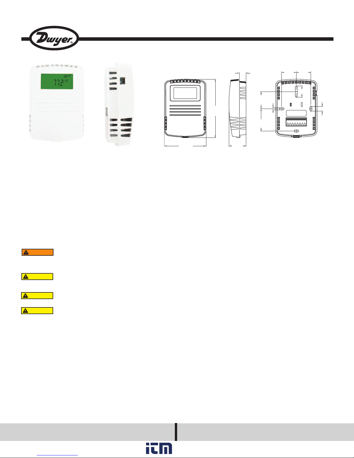
hown with optional LCD display
S
Bulletin H-RHP-W
Series RHP-W Wall Mount Humidity/Temperature/Dew Point Transmitter
Specifications - Installation and Operating Instructions
The Series RHP-W Wall Mount Humidity/Temperature/Dew Point Transmitter
is the most versatile room transmitter on the market. The stylish housing is well
vented to provide air flow across the sensor to improve measurement accuracy. An
ptional LCD display can be integral to the transmitter or a remote display can be
o
rdered for building balancing or LEED validation. The LCD display indicates the
o
mbient temperature along with the humidity or dew point. The transmitter has
a
internal dip switches to select the temperature engineering units and whether the
transmitter outputs humidity or dew point.
The humidity and temperature sensors are field replaceable to reduce service cost
and inventory. The humidity and the dew point are measured using a capacitive
polymer sensor that completely recovers from 100% saturation. The humidity and
dew point can have either a current or voltage output, while the optional temperature output can be a current, voltage, RTD or thermistor. For models with current
or voltage for the temperature output, the temperature range is field selectable.
INSTALLATION
WARNING
Make sure all connections are in accordance with the job wiring diagram and in
accordance with national and local electrical codes. Use copper conductors only.
CAUTION
age.
CAUTION
CAUTION
designed for AC voltage operation.
Disconnect power supply before installation to prevent electrical
shock and equipment damage.
Use electrostatic discharge precautions (e.g., use of wrist
straps) during installation and wiring to prevent equipment dam-
Avoid locations where severe shock or vibration, excessive
moisture or corrosive fumes are present.
Do not exceed ratings of this device, permanent damage not
covered by warranty may result. The 4-20 mA models are not
PECIFICATIONS
S
Relative Humidity Range: 0 to 100% RH.
Temperature Range: -40 to 140°F (-40 to 60°C) for thermistor and RTD sensors.
-20 to 140°F (-28.9 to 60°C) for solid state temperature sensors.
Dew Point Temperature Range: -20 to 140°F (-28.9 to 60°C); 0 to 100°F
-17.8 to 37.8°C); 40 to 90°F (4.4 to 32.3°C); -4 to 140°F (-20 to 60°C) field selec-
(
table ranges.
Accuracy:
RH: Model RHP2 ±2% 10-90% RH @ 25°C; Model RHP3 ±3% 20-80% RH @
25°C.
Thermistor Temperature Sensor: ±0.4°F @ 77°F (±0.22°C @ 25°C).
RTD Temperature Sensor: DIN Class B; ±0.54°F @ 32°F (±0.3°C @ 0°C).
Solid State Temperature Sensor: ±0.9°F @ 72°F (±0.3°C @ 25°C).
Hysteresis: ±1%.
Repeatability: ±0.1% typical.
Temperature Limits: -40 to 140°F (-40 to 60°C).
Storage Temperature: -40 to 176°F (-40 to 80°C).
Compensated Temperature Range: -4 to 140°F (-20 to 60°C).
4-20 mA Loop Powered Models:
Power Requirements: 10-35 VDC.
Output Signal: 4-20 mA, 2 channels for humidity/solid state temperature sensor
models (loop powered on RH). Switch selectable RH/dew point. Switch
selectable normal or reverse output.
0-5/10V Output Models:
Power Requirements: 15-35 VDC or 15-29 VAC.
Output Load: 5 mA max., 2 channels for humidity/solid state temperature
sensor models. Switch selectable 0-10V/2-10V or 0-5V/1-5V output. Switch
selectable RH/dew point. Switch selectable normal or reverse output.
Solid State Temperature Sensor Output Ranges: Switch selectable,
-20 to 140°F (-28.9 to 60°C); 0 to 100°F (-17.8 to 37.8°C); 40 to 90°F
(4.4 to 32.3°C); -4 to 140°F (-20 to 60°C).
Response Time: 15 seconds.
Electrical Connections: Screw terminal block.
Drift: <1% RH/year.
RH Sensor: Capacitance polymer.
Enclosure Material: White polycarbonate.
Display: Optional LCD, backlit on 0-5/10V models. Switch selectable %RH or dew
point, °F/°C.
Display Resolution: RH: 1%; Temperature: 0.1°F (0.1°C); Dew Point: 1°F (1°C).
Weight: 0.3 lb (0.14 kg).
Agency Approvals: CE.
DWYER INSTRUMENTS, INC.
Phone: 219/879-8000 www.dwyer-inst.com
P.O. Box 373 • Michigan City, IN 46360-0373, U.S.A. Fax: 219/872-9057 e-mail: info@dwyer-inst.com
www. .com
information@itm.com1.800.561.8187
Page 2

1 2 3 4 5 6 7 81 2 3 4 5 6 7 8
POWER
SUPPLY
POWER
SUPPLY
+ -+ -
RH RECEIVERRH RECEIVER
++
--
TEMP RECEIVERTEMP RECEIVER
PASSIVE TEMP.
SENSOR
PASSIVE TEMP.
SENSOR
(IF PRESENT)(IF PRESENT)
(IF PRESENT)(IF PRESENT)
++
--
4-20MA4-20MA
4-20MA4-20MA
B
OTTOM TAB
H
INGE
TO REMOVE COVER
APPLY PRESSURE TO
BOTTOM TAB WHERE
INDICATED AND THE
TWO PARTS
WILL BECOME
UNHINGED AT TOP
REVERSE PROCESS
TO APPLY COVER
MOUNTING
BACK PLATE
S
ELF-LATCHING
C
OVER
M
OUNTING
S
CREWS
igure 1
F
. Push tab on bottom of cover and lift cover from back plate. (See Figure 1).
1
2. Select the mounting location, away from diffusers, lights, or any external
influences.
3. Mount transmitter on a vertical surface to a standard electrical box using the two
#6 M2C type screws provided.
. Pull wires through sub base hole and make necessary connections.
4
. Reattach cover to base plate.
5
Wiring
Use maximum 18 AWG wire for wiring to terminals. Refer to figures 2 through 5 for
wiring information.
Current Output Models (RHP-XW1X)
Current output models must be powered with 10-35 VDC supply voltage. Wire the
RH current output as shown in Figure 2. If the unit has a 4-20 mA temperature output, wire the temperature receiver between terminal 3 and the negative terminal of
he power supply. If the unit has a passive temperature sensor, wire to terminals 4
t
nd 5. If the RH output is not required, wire the negative terminal of the power sup-
a
ply to terminal 1 of the transmitter. If the temperature output is not used, it may be
left disconnected.
odels with Selectable Current or Voltage Outputs (RHP-XW44)
M
hese models may be wired for current or voltage output. Note that both outputs
T
ust be wired either for current or voltage. It is not possible to wire one output for
m
urrent, and the other for voltage.
c
Prior to wiring, verify that the Current/Voltage select switch is set to current or voltage as desired. Refer to “Setting the Current/Voltage Select Switch”.
urrent Output Selected: Wire as shown in Figure 4. Current outputs must be
C
owered with 10-35 VDC. If the RH output is not required, wire the negative termi-
p
al of the power supply to terminal 1 of the transmitter. All units come with 4-20 mA
n
RH and Temperature outputs. If the 4-20 mA temperature output is not used it
maybe left disconnected. If the unit has a passive temperature sensor, wire to terminals 7 and 8.
igure 4
F
oltage Output Selected: Voltage outputs may be powered with 15-35 VDC or 15-
V
29 VAC. Note polarity when using DC power. Wire the RH voltage output as shown
in Figure 5. If the unit has a voltage temperature output, wire the temperature
receiver between terminal 6 and the negative terminal of the power supply. All units
come with RH and Temperature voltage outputs. If the temperature or RH voltage
output is not used it may be left disconnected. If the unit has a passive temperature
sensor, wire to terminals 7 and 8.
Figure 2
Voltage Output Models (RHP-XW2X)
Wire as shown in Figure 3. Voltage outputs may be powered with 15-35 VDC or 1529 VAC. Note polarity when using DC power. If the unit has a voltage temperature
output, wire the temperature receiver between terminal 4 and negative terminal of
power supply. If the unit has a passive temperature sensor, wire to terminals 5 and
6. For units with RH and temperature voltage outputs, the RH or Temperature out-
put may be used by itself.
Figure 3
Setting the Current/Voltage Select Switch
Remove the cover of the unit as shown in Figure 1. The Current/Voltage select
switch is located on the back of the circuit board. Set the switch “IOUT” for current,
“VOUT” for voltage.
www. .com
Figure 5
Figure 6
information@itm.com1.800.561.8187
Page 3

IP SWITCH SETTINGS
D
o access the DIP SWITCH, remove the cover of the unit as shown in Figure 1. The
T
IP SWITCH is located on the back of the circuit board.
D
igure 7
F
ALL DIP SWITCHES are factory set to “ON”
V/10V Output Select (Applies only to Voltage Output units)
5
IP SWITCH#1 OFF: Output = 0-5V
D
IP SWITCH#1 ON: Output = 0-10V
D
Zero Suppression (Applies only to Voltage Output Units)
DIP SWITCH#2 OFF : Output range = 1-5V or 2-10V, depending on output range
DIP SWITCH#2 ON : Output range = 0-5V or 0-10V, depending on output range
pper Display reads RH or DEW POINT
U
IP SWITCH#3 OFF: Upper Display reads Dew Point
D
DIP SWITCH#3 ON: Upper Display reads RH
RH OUTPUT, Normal or Invert
DIP SWITCH#4 OFF: Output is inverted
IP SWITCH#4 ON: Output is Normal
D
hen set to normal output, the output increases as the RH increases. When set to
W
inverted output, the output decreases as the RH increases.
Example: Normal 4-20 mA output, 0%RH = 4 mA, 100% RH = 20 mA
TEMP OUTPUT, Normal or Invert
DIP SWITCH#5 OFF: Output is inverted
DIP SWITCH#5 ON: Output is Normal
When set to normal output, the output increases as the temperature increases.
When set to inverted output, the output decreases as the temperature increases.
Example: Normal 4-20 mA output, -20°F = 4 mA, +140°F = 20 mA
Inverted 4-20 mA output, 0%RH = 20 mA, 100% RH = 4 mA
Inverted 4-20 mA output, -20°F = 20 mA, +140°F = 4 mA
ROUBLESHOOTING
T
. Verify that the unit is mounted in the correct position.
1
. 4-20 mA Models:
2
erify appropriate supply voltage. The transmitter requires a minimum of 10 and a
V
maximum of 35 VDC at its connection for proper operation. Choose a power supply with a voltage and current rating which meets this requirement under all operating conditions. If the power supply is unregulated, make sure voltage remains
ithin these limits under all power line conditions. Ripple on the supply should not
w
xceed 100 mV.
e
oop Resistance – The maximum allowable loop resistance depends on the
L
power supply voltage. Maximum loop voltage drop must not reduce the transmitter
voltage below the 10 VDC minimum. Maximum loop resistance can be calculated
with the following equation. Vpsis the power supply voltage.
ax
ax
=
=
Vps-10.0
20 mA
Vps-10.0-V
20 mA
rec
s the receiver fixed voltage.
i
rec
R
m
Some receivers, particularly loop powered indicators, may maintain a fixed loop
voltage to power the device. This voltage drop must also be subtracted from the
ower supply voltage when calculating the voltage margin for the transmitter. The
p
ollowing equation takes this into account. V
f
R
m
-10 V Output Models:
0
erify appropriate supply voltage. The 0-10V output models require a DC supply of
V
5 to 35 V or an AC supply of 15-29 V for proper operation maximum. Maximum
1
output load is 5 mA.
FIELD SENSOR REPLACEMENT
Replacement sensors are available. Replacement sensors are factory calibrated
and do not require any further calibration.
1. Remove cover as shown in Figure 1.
2. Remove existing sensor as shown in Figure 8.
3. Replace the sensor with appropriate replacement sensor.
4. Reattach cover to base plate.
°F/°C Select
DIP SWITCH#6 OFF: °C
DIP SWITCH#6 ON: °F
Temperature Output Range Select
Range
-4 to +140°F (-20 to +60°C)
+40 to +90°F (+4.4 to +32.2°C)
0 to +100°F (-17.8 to +37.8°C)
-20 to +140°F (-28.9 to +60°C)
The temperature range applies only to the current or voltage output. If the unit has
a display, it will display temperature from -40 to +140°F (-40 to +60°C). If the unit is
set to read DEW POINT, the output range of the DEW POINT will be the same as
the Temperature Output Range.
Note: The display will indicate temperature even if the unit does not have a temperature output.
Dip Switch 7
OFF
OFF
ON
ON
Dip Switch 8
OFF
ON
OFF
ON
Figure 8
Remote Display
For models that are ordered without an integral LCD display, remote display Model
A-449 can be used to display the temperature and humidity or dew point. The mini
USB plug of the remote display plugs into the receptor on the side of the housing.
After a short warm up time, the display will begin to show the current temperature
and humidity or dew point measurements. Humidity or dew point can be selected
via the internal dip switches as described earlier in this manual.
NOTICE
ESD. Failure to exercise good ESD practices may cause damage to the sensor.
Sensor is sensitive to Electro-Static Discharge (ESD). Follow
industry standard practice for control and protection against
www. .com
information@itm.com1.800.561.8187
Page 4

0MAINTENANCE
Upon final installation of the Series RHP-W Temperature/Humidity/Dew Point
Transmitter and the companion receiver, no routine maintenance is required. A peri-
dic check of the system calibration is recommended. Except for sensor replace-
o
ent, t he Series RHP-W is not field serviceable and should be returned if repair is
m
eeded (field repair should not be attempted and may void warranty). Be sure to
n
nclude a brief description of the problem plus any relevant application notes.
i
Contact customer service to receive a return goods authorization number before
shipping.
odel Chart
M
Example
Series
Accuracy
ousing Type
H
H Output
R
Temperature
Sensor/Output
ption
O
ACCESSORIES
Replacement sensor part number table:
RHP Model #
RHP-2(W)XA
RHP-2(W)XB
RHP-2(W)XC
RHP-2(W)XD
RHP-2(W)XE
RHP-2(W)XF
RHP-2(W)X(0,1, 2, 4)
RHP-3(W)XA
RHP-3(W)XB
RHP-3(W)XC
RHP-3(W)XD
RHP-3(W)XE
RHP-3(W)XF
RHP-3(W)X(0, 1, 2, 4)
D
1
RHP
HP
R
A
2
2
3
W
1
2
4
A
B
C
D
E
F
0
1
2
4
Replacement Sensor Part #
RHPS-D2A
RHPS-D2B
RHPS-D2C
RHPS-D2D
RHPS-D2E
RHPS-D2F
RHPS-D20
RHPS-D3A
RHPS-D3B
RHPS-D3C
RHPS-D3D
RHPS-D3E
RHPS-D3F
RHPS-D30
HP-2D1A-LCD
R
CD
L
H/Passive Temperature Sensor Transmitter
R
2% Accuracy
3% Accuracy
Wall Mount
-20 mA
4
-10V/0-5V
0
-10V/0-5V/4-20 mA
0
10K @ 25°C Thermistor Dwyer Curve A
10K @ 25°C Thermistor Dwyer Curve B
3K @ 25°C Thermistor Dwyer Curve C
100Ω RTD DIN 385
KΩ RTD DIN 385
1
0KC 25°C Thermistor Curve F
2
ONE
N
4-20 mA Solid State Sensor
0-10V/0-5V mA Solid State Sensor
0-10V/0-5V/4-20 mA Sensor
LCD Display
CD
L
o Options
N
lank
B
RESISTANCE VS TEMPERATURE TABLE
esistance Curves (in Ohms)
°F
-67.0
58.0
-
49.0
-
40.0
-
31.0
-
-22.0
-13.0
-4.0
5
4.0
1
3.0
2
2.0
3
41.0
50.0
59.0
8.0
6
7.0
7
86.0
95.0
104.0
113.0
22.0
1
31.0
1
40.0
1
149.0
58.0
1
67.0
1
76.0
1
185.0
194.0
203.0
212.0
221.0
230.0
239.0
248.0
257.0
266.0
275.0
284.0
293.0
302.0
R
A
607800.00
4
3
2
1
135200.00
102900.00
.0
41200.00
23600.00
39700.00
79200.00
78910.00
1020.00
6
7540.00
4
7310.00
3
9490.00
2
23460.00
18780.00
15130.00
2260.00
1
0000.00
1
8194.00
6752.00
5592.00
4655.00
893.00
3
271.00
3
760.00
2
2339.00
990.00
1
700.00
1
458.00
1
1255.00
1084.00
939.30
816.80
712.60
623.60
547.30
481.80
425.30
376.40
334.00
297.20
265.10
237.00
B
963849.00
70166.00
6
71985.00
4
36479.00
3
42681.00
2
176974.00
130421.00
97081.00
2957.00
7
5329.00
5
2327.00
4
2650.00
3
25392.00
19901.00
15712.00
2493.00
1
0000.00
1
8057.00
6531.00
5326.00
4368.00
602.00
3
986.00
2
488.00
2
2083.00
752.00
1
480.00
1
255.00
1
1070.00
915.50
786.60
678.60
587.60
510.60
445.30
389.60
341.90
301.00
265.80
235.30
208.90
186.10
C
289154.70
2
1
1
emperature
T
°C
-55
50
45
40
35
-
-30
-25
-20
15
10
5
-
0
5
10
15
0
2
5
2
30
35
40
45
0
5
5
5
0
6
65
0
7
5
7
0
8
85
90
95
100
105
110
115
120
125
130
135
140
145
150
01049.80
41595.50
00943.70
2804.30
7
53092.20
39126.30
29.124.30
1887.10
2
6598.70
1
2698.10
1
795.00
9
7617.60
5970.30
4713.60
747.90
3
000.00
3
2417.10
1959.30
1597.80
1310.40
080.60
1
95.80
8
46.40
7
624.90
25.60
5
44.00
4
76.50
3
321.00
274.65
235.98
203.58
176.28
153.18
133.59
116.88
102.57
90.30
79.74
70.59
62.67
55.83
D
78.32
0.31
8
2.29
8
4.27
8
6.25
8
88.22
90.19
92.16
4.12
9
6.09
9
8.04
9
00.00
1
101.95
103.90
105.85
07.79
1
09.74
1
111.67
113.61
115.54
117.47
19.40
1
21.32
1
23.24
1
125.16
27.08
1
28.99
1
30.90
1
132.80
134.71
136.61
138.51
140.40
142.29
144.18
146.07
147.95
149.83
151.71
153.58
155.46
157.33
E
783.2
03.1
8
22.9
8
42.7
8
62.5
8
882.2
901.9
921.6
41.2
9
60.9
9
80.4
9
000.0
1
1019.5
1039.0
1058.5
077.9
1
097.4
1
1116.7
1136.1
1155.4
1174.7
194.0
1
213.2
1
232.4
1
1251.6
270.8
1
289.9
1
309.0
1
1328.0
1347.1
1366.1
1385.1
1404.0
1422.9
1441.8
1460.7
1479.5
1498.3
1517.1
1535.8
1554.6
1573.3
F
2394000.00
646200.00
1
145800.00
1
06800.00
8
74400.00
5
413400.00
300400.00
220600.00
63.500.00
1
22280.00
1
2240.00
9
0160.00
7
53780.00
41560.00
32340.00
5360.00
2
0000.00
2
15892.00
12704.00
10216.00
8264.00
722.00
6
498.00
5
520.00
4
3734.00
100.00
3
586.00
2
166.00
2
1822.60
1540.00
1306.40
1112.60
951.00
815.80
702.20
606.40
525.60
N/A
N/A
N/A
N/A
N/A
©Copyright 2012 Dwyer Instruments, Inc. Printed in U.S.A. 12/12 FR# 03-443752-00 Rev. 3
DWYER INSTRUMENTS, INC.
Phone: 219/879-8000 www.dwyer-inst.com
P.O. Box 373 • Michigan City, IN 46360-0373, U.S.A. Fax: 219/872-9057 e-mail: info@dwyer-inst.com
www. .com
information@itm.com1.800.561.8187
 Loading...