


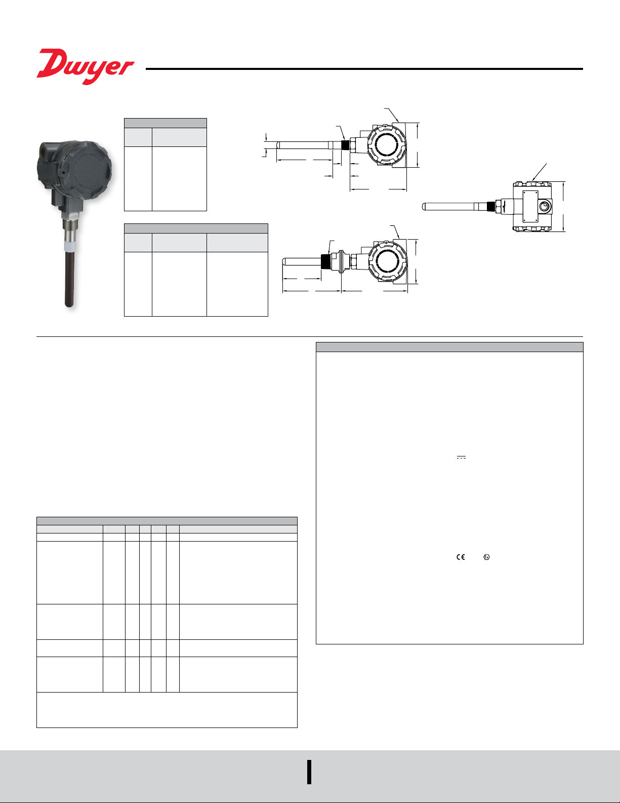
Series PMT2 Particulate Transmitter
2X 1/2˝ NPT OR M20 ELECTRICAL ENTRY
[15.88]
L
1.13]
[147.64]
®
Specications - Installation and Operating Instructions
Bulletin PC-PMT2-M
The SERIES PMT2 Particulate Transmitter is designed to measure particulate emission
levels from dust collector discharge. Using DC coupled electrostatic induction sensing
technology, the transmitter monitors a pA current that is generated as particulate
passes near the probe; a 4 to 20 mA signal will vary based on the particulate level. The
PMT2 offers 6 sensitivity ranges allowing the user to choose the range that will best t
the application. The range and test selector switch can also be set to output a 4 mA or
20 mA signal to assist with set up or trouble shooting. Averaging time setting can be
used to dampen the signal if desired.
FEATURES/BENEFITS
• Simple 2-wire installation for PLC and control panels
• Non-stick PTFE coated probe to prevent false readings from moist and conductive
dusts, condensate, and dust buildup
• Remote zero calibration helps to decrease maintenance time
MODEL CHART
Example PMT2 -05 -A -U2 PMT2-05-A-U2
Series PMT2 Particulate transmitter
Probe
Length
Process
Connection
Enclosure Rating A2
Options STM2Stainless steel tag
*Options that do not have ATEX or IECEx.
Attention: Units without the A2 sufx are not Directive 2014/34/EC (ATEX)
compliant. These Units are not intended for use in potentially hazardous
atmospheres in the EU. These unites may be CE marked for other Directives
of the EU.
THREADED MOUNT
Probe
LengthAin [mm]
3˝
3 [76.20]
5˝
5 [127.00]
10˝
10 [254.00]
15˝
15 [381.00]
20˝
20 [508.00]
30˝
30 [762.00]
36˝
36 [914.40]
1.5˝ TRI-CLAMP MOUNT
Probe
LengthAin [mm]
3˝
3-1/2 [88.90]
5˝
5-1/2 [139.70]
10˝
10-1/2 [266.70]
15˝
15-1/2 [393.70]
20˝
20-1/2 [520.70]
30˝
30-1/2 [744.70]
36˝
36-1/2 [927.10]
03
05
10
15
20
30
36
A
B
C
3˝ probe length
5˝ probe length
10˝ probe length
15˝ probe length
20˝ probe length
30˝ probe length
36˝ probe length
3/4˝ male NPT
1.5˝ tri-clamp kit with 1˝ male NPT
3/4˝ male BSPT
ATEX and IECEx (IS)
U2
UL (IS)*
Female M20 electrical entries
(female 1/2˝ NPT standard)
B
in [mm]
1-25/32 [45.24]
3-25/32 [96.04]
8-25/32 [223.04]
13-25/32 [350.04]
18-25/32 [477.04]
28-25/32 [731.04]
34-25/32 [883.44]
3/4˝ NPT or 3/4˝ BSPT
5/8
“A”
3/4˝ Male NPT OR 3/4˝ Male BSPT Mount
2X 1/2˝ NPT OR M20 ELECTRICAL ENTRY
“B”
“A”
1.5˝ Tri-Clamp Option Mount
SPECIFICATIONS
Service: Air and compatible gases, any type of particulate conductive or nonconductive.
Wetted Materials: 316L SS, silicone, and PTFE.
Enclosure: Powder coated aluminum.
Accuracy: ±5% of reading.
Particulate Size: 0.3 microns and higher.
Detection Range: 5 to 5000 pA (6 selectable range options).
Temperature Limits: Ambient: -40 to 145°F (-40 to 63°C); Process: -40 to 248°F
(-40 to 120°C).
Pressure Limit: 30 psi (2 bar).
Output Signal: 4 to 20 mA.
Power Requirements: 12 to 28 VDC ( ).
Electrical Connection: Two 1/2˝ female NPT electrical entries or two M20 electrical
entries (A2 sufx only).
Terminal Block: Removable (16 to 20 AWG wire).
Process Connection: See model chart. BSPT process connections are not UL
listed.
Probe Lengths: See model chart.
Enclosure Rating: UL Type 4 (IP66) ATEX/IECEx IP65.
Mounting Orientation: Any.
Averaging Time: 1 to 360 s (10 selectable options).
Weight: Varies with length of probe and type of mount.
Agency Approvals: CE, cULus; ATEX Compliant: 0518 II 1 G Ex ia IIB T4 GA
(-40°C ≤ Tamb ≤ 63°C) (-40°C ≤ T
(-40°C ≤ Tamb ≤ 63°C) (-40°C ≤ T
16ATEX1768 X. ATEX Standards: EN 60079-0:2012/A11:2013; EN 60079-11:2012.
IECEx Certied: Ex ia IIB T4 Ga (-40°C ≤ Tamb ≤ 63°C) (-40°C ≤ T
Ex ia IIIC T120°C Da (-40°C ≤ Tamb ≤ 63°C) (-40°C ≤ T
Certicate of Conformity: IECEx UL 16.013X. IECEx Standards: IEC 60079-0: 2011;
IEC 60079-11: 2011. UL Listed Intrinsically Safe for Class I, Groups C and D; Class
II, Groups E, F and G; Class III; Class I Zone 0 AEx ia IIB T4 Ga; Class I Zone 0 Ex
ia IIB T4 Ga.
1-1/2
[38.10]
1˝ NPT
3/4
[19.05]
4-15/16
[125.41]
5-13/16
3-29/32
[99.22]
3-29/32
[99.22]
Process ≤ 120°C) / II 1 D Ex ia IIIC T120°C Da
Process ≤ 120°C). Type Certicate No.: DEMKO
ALLOW 1-1/4˝ [32]
FOR COVER REMOVA
BOTH SIDES
Process ≤ 120°C).
Process ≤ 120°C) /
[11
4-3/8
DWYER INSTRUMENTS, INC.
P.O. BOX 373 • MICHIGAN CITY, INDIANA 46360, U.S.A.
Phone: 219/879-8000
Fax: 219/872-9057
www.dwyer-inst.com
e-mail: info@dwyermail.com

OPERATING PRINCIPLE
Technology
The PMT2 utilizes a highly reliable DC coupled electrostatic induction sensing
technology. The sensor probe is mounted in an airow stream such as a pipe, duct
or stack. The inductive effect takes place when particulate passes near the probe
transferring a charge from the particulate to the probe. A microprocessor lters and
processes the signal into a output that is linear to the mass concentration of particulate.
The PTFE coated probe ensures reliable operation with all types of particulate including
moist powders and highly conductive dusts. The PTFE coated probe eliminates the
need for an air purge and keeps maintenance to a minimum.
Particulate Monitoring
The PMT2 is specically designed to continuously monitor the particulate levels in air
ow from stacks or other emission points being passed through a lter within an air
ltration system. The transmitter should be installed in the exhaust ductwork and can
be used in conjunction with various types of bag, ceramic, cartridge or cyclone lters.
When the PMT2 is rst installed a baseline reading must be measured and noted. This
baseline reading is application dependent and should be measured independently for
each installation. From this baseline the operator will monitor output signal from the
PMT2. The increase in mA output indicates a rising level of particulate in the air stream
which indicates that lters are either wearing out or broken.
The PMT2 is designed to give a proportional output based on the particulate levels in
a duct or pipe, it is not designed to output a signal based on the particulate volumetric
ow. Different types of particulate carry different charges, meaning that two particulates
owing at the same volumetric ow rate could have different output response. The
PMT2 is designed to nd a baseline under ideal operating conditions and allow an
operator to watch the output signal for increases that would signify the bags or lters
are starting to wear or break. The six sensitivity ranges allow the PMT2 to monitor
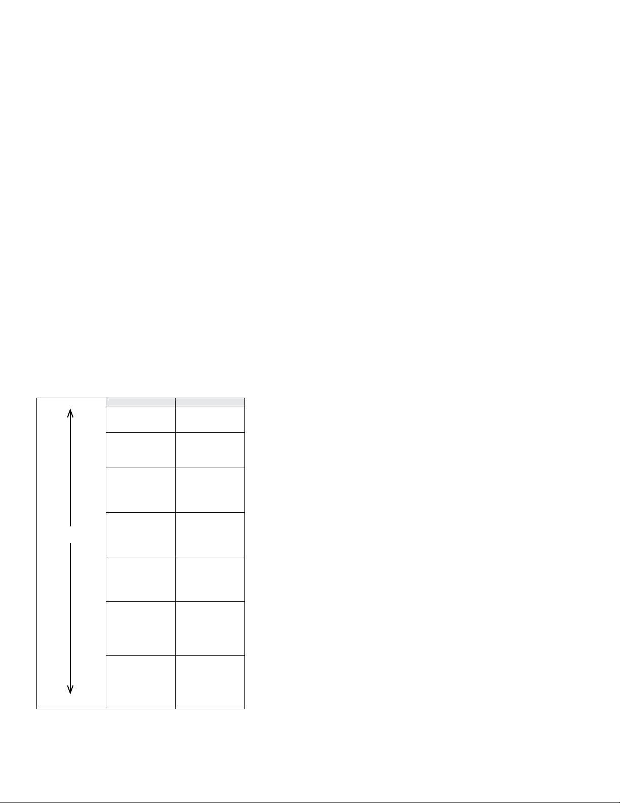
particulates with low charge properties or high charge properties. As a reference, Table
1 lists particulate charge properties and the suggested range.
INSTALLATION
Unpacking
Remove the PMT2 from the shipping carton and inspect for damage. If damage is
found, notify the carrier immediately.
Location
The following factors should be considered when determining the installation location
for the PMT2:
• Make sure the transmitter is rated for the area classication it will be mounted in.
• Mount the transmitter in a location that will not exceed the temperature and pressure
ratings listed in the specications. The process pressure should not exceed 30 psi (2
bar).
• Make sure the 4 to 20 mA signal wires are not sharing the same conduit with high
voltage power wires.
• Make sure the location the transmitter is mounted in meets the NEMA or IP rating
for the enclosure.
• Locate the transmitter in a location were it can be accessed in case service is
required.
The PMT2 should be mounted in a grounded metal stack, pipe or duct. It should not
be mounted in berglass or plastic stacks, pipes or ducts. The sensing probe should
reach 1/2 to 2/3 the way across the stack, pipe or duct to ensure accurate readings.
For the most stable and accurate readings it is recommended to mount the PMT2 in
a location where the air ow is as laminar as possible. Avoid mounting the transmitter
close to blowers and dampers that cause turbulence. It is ideal to mount the PMT2 in
an area with two upstream duct diameters and one down stream duct diameter that
are free of turbulent causing objects. The sensing probe is coated in a non-stick PTFE
preventing material from coating the probe reducing the need for cleaning or an air
purge.
Neutral
Particulate Suggested Range
Human Hands
Asbestos
Rabbit Fur
Acetate
Glass
Mica
Human Hair
Nylon
PositiveNegative
Wood
Fur
Lead
Silk
Aluminum
Paper
Cotton
Steel
Wood
Mylar™
Nickel/Copper
Silver/Brass
Gold/Platinum
Sulfur
Acetate Rayon
Polyester
Styrene (Styrofoam)
Acrylic
Saran™
Polyurethane
Polyethylene
Polypropylene
Vinyl (PVC)
Silicon
PTFE
Silicone Rubber
Table 1: Suggested Ranges
5 to 5000 pA
5 to 1000 pA
5 to 500 pA
5 to 100 pA
5 to 500 pA
5 to 1000 pA
5 to 5000 pA
WIRING
(IF USED)
REMOTE ZERO
NOTICE
• Always install or service this device with the power off and where
required install a disconnect lockout
• Use 16 to 20 AWG copper wire only for line and load connections. Installation must
be made in accordance with local codes and regulations such as the National Electric
Code
• Degree of protection TYPE 4 (IP66) is maintained when suitable glands/plugs are
used in conjunction with UL Listed models
WARNING
HAZARDOUS LOCATIONS
To prevent ignition of hazardous locations the following cau-
tions should be taken:
• Keep device covers tightly closed in operation
• De-energize supply circuit before opening device covers
• Replace device covers before energizing the electrical circuits
• Device is not eld repairable and should be returned to Dwyer Instruments if repair
is needed
WARNING
INTRINSIC SAFETY SPECIFIC CONDITIONS OF USE
To maintain Intrinsic Safety the following cautions should be
taken:
• 4-20 mA signal and remote zero must be treated as separate circuits
• Enclosure parts are constructed of aluminum. Enclosure must be protected from
ignition hazard due to impact or friction
• All openings to enclosure must be sealed using suitable glands and/or plug main-
taining a minimum IP rating of IP66 for UL Listed models and IP65 for ATEX/IECEx
compliant models
• Substitution of parts may impair Intrinsic Safety.
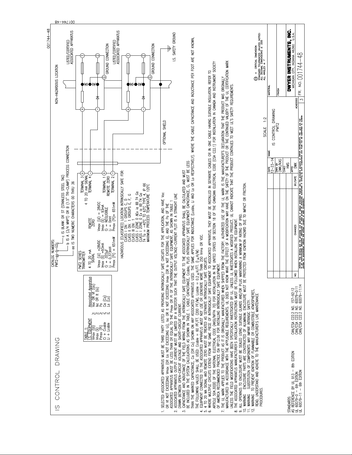
CONTROL DRAWING UL LISTED INTRINSIC SAFETY (SUFFIX U2):
UL Listed Intrinsically Safe for use in Class I Div. 1 Groups C and D; Class II Div. 1
Groups E, F and G; Class III Div. 1; Class I Zone 0 AEx ia IIB T4 Ga; Class I Zone 0 Ex
ia IIB T4 Ga; T4@63°C when installed in accordance with Control Drawing 001744-48
on page 6 of this document.
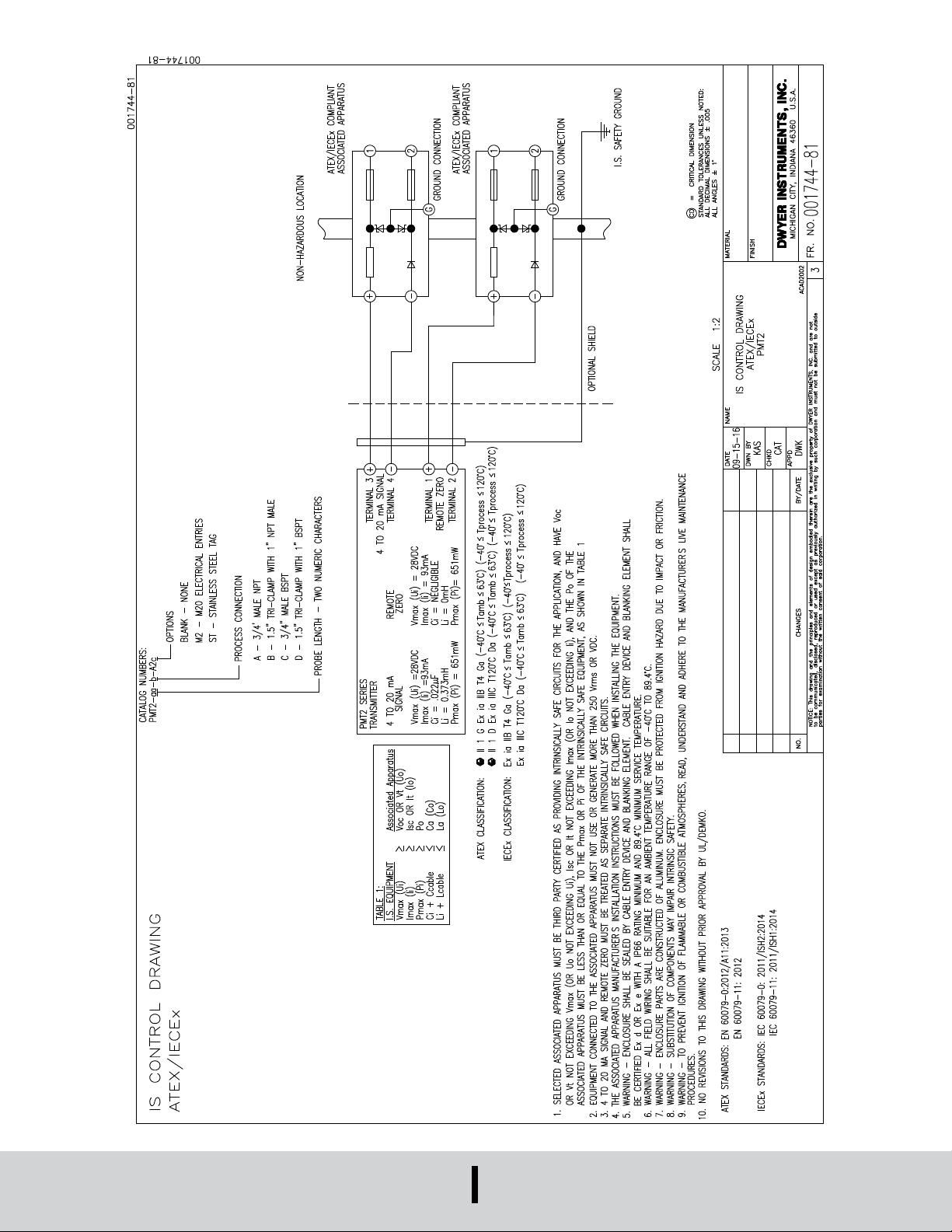
ATEX COMPLIANT (SUFFIX A2)
II 1 G Ex ia IIB T4 Ga (-40°C ≤ Tamb ≤ 63°C) (-40°C ≤ T
IIIC T120°C Da (-40°C ≤ Tamb ≤ 63°C) (-40°C ≤ T
Process ≤ 120°C) / II 1 D Ex ia
Process ≤ 120°C) when installed in
accordance with Control Drawing 001744-81 on page 7 of this document.
POWER SUPPLY REQUIREMENTS
The maximum DC power supply is 28 VDC. The minimum required DC power supply
is based upon the following:
1. Minimum DC voltage requirement of the Model PMT2.
2. Total load resistance.
3. Total leadwire resistance.
4. Zener barrier voltage drop (Model PMT2-XX-X-X2 only).
The formula for calculating the DC Power Supply is:
VDC = VPMT2 + VLOAD + VLEADWIRE + VBARRIER
Where VPMT2 = 9.5 V
VLOAD = Total load resistance X 20 mA
VLEADWIRE = Total leadwire resistance X 20 mA
VBARRIER = 8.1 V (Typical zener barrier voltage drop for this application)
Example 1: Calculate minimum DC power supply for intrinsically safe models
Step 1 VPMT2 = 9.5 V
Step 2 Calculate VLOAD. Using the industry standard 250 Ω conversion
resistor, VLOAD = 250 X 20 mA = 5 V.
Step 3 Calculate VLEADWIRE. For this example assume a leadwire
resistance of 10 Ω, VLEADWIRE = 10 X 20 mA = 0.2 V
Step 4 VBARRIER = 8.1 V
Step 5 VDC = VPMT2 + VLOAD + VLEADWIRE + VBARRIER = 9.5 + 5 +
0.2 + 8.1 = 22.8 V
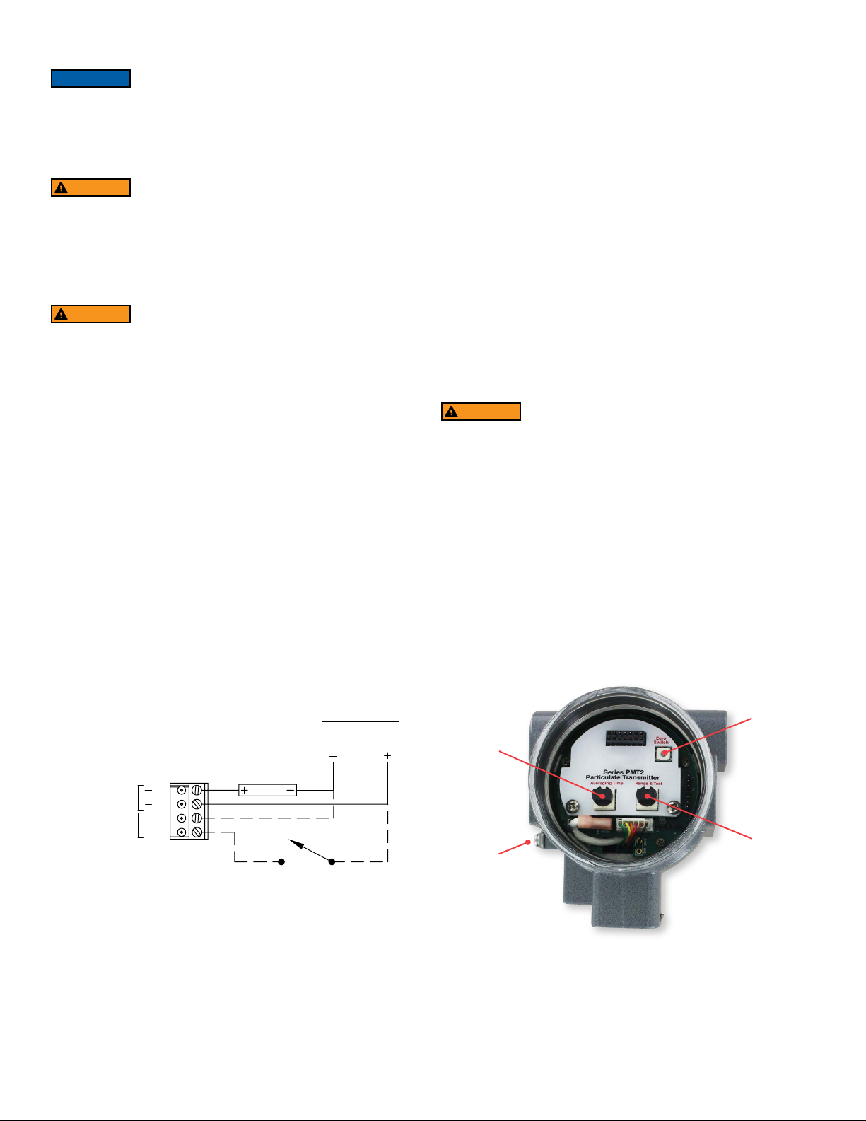
CONTROLS
WARNING
LIVE MAINTENANCE PROCEDURE
Live maintenance of Zero, Averaging Time, Range and Test
controls cannot be performed when a ammable or combustible atmosphere is
present.
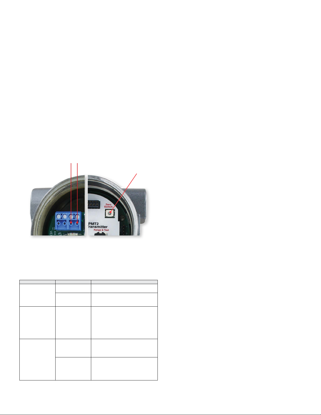
Zero Switch (see Figure 2)
Press and hold the switch for 3 seconds and the PMT2 will digitally re-zero. It is
recommended to re-zero after a lter failure or lter changes. Re-zeroing should only
be done when there is no air ow in the duct.
Averaging Time Selection Switch
The PMT2 will average the output for the selected amount of time. This will dampen
output spikes caused during normal lter cleaning cycles.
IECEx COMPLIANT (SUFFIX A2)
Ex ia IIB T4 Ga (-40°C ≤ Tamb ≤ 63°C) (-40°C ≤ T
Da (-40°C ≤ Tamb ≤ 63°C) (-40°C ≤ T
Process ≤ 120°C) when installed in accordance
Process ≤ 120°C) / Ex ia IIIC T120°C
with Control Drawing 001744-81 on page 7 of this document.
INTRINSIC SAFETY INPUT PARAMETERS:
4-20 mA Signal, Vmax (Ui) = 28 V; Imax (li) = 93 mA; Ci = .022 μF; Li = 0.373 mH;
Pmax (Pi) = 651 mW
Remote Zero, Vmax (Ui) = 28 V; Imax (li) = 93 mA; Ci = Negligible; Li = 0 mH; Pmax
(Pi) = 651 mW
POWER
SUPPLY
RECEIVER
4 to 20mA
4
3
2
1
REMOTE ZERO SWITCH
Figure 1: General Installation Wiring (Non-IS)
Range and Test Selection Switch
There are 6 sensitivity ranges that can be selected based on the material the PMT2
will be sensing (see Table 1). There is also an option to output a 4 mA or 20 mA signal,
these options can assist in the installation of the transmitter or trouble shooting.
Zero Switch
Averaging
Time
Range &
Grounding
Screw
Tes t
Figure 2
SET UP
1000 pA
Spike Alarm
TIME
Mounting
Make sure the PMT2 is securely mounted to the stack, pipe or duct to prevent vibration
during operation. Make sure the transmitter is grounded properly.
Control Signal Set Up
Check the power supply wiring to make sure the polarity is correct before powering
the PMT2. Turn the power on to the transmitter and turn the Range and Test selector
switch to 4 mA (position 2). The PMT should output 4 mA, check the output with a
multi-meter or at the device (PLC, Display, etc.) receiving the output signal. Once it is
veried the 4 mA signal is being received, switch the Range and Test selector switch to
20 mA (position 1) and repeat the process. If the output is 0 mA, make sure the power
supply is on and check for loose wires.
Range and Test Selection
When selecting one of the 6 available ranges, the baseline and maximum peak signals
that take place during lter cleaning must be taken into account. The selected ranges
should have enough resolution to monitor the baseline and capture the maximum
peaks during a cleaning cycle. The four linear ranges output 4 mA at 5 pA and 20 mA
at maximum range. The two logarithmic ranges have ner resolution at the low end of
the ranges and less at the high end.
Switch Position Range Output
1 Test 20 mA
2 Test 4 mA
3 5 to 100 pA 5 pA = 4 mA
4 5 to 500 pA 5 pA = 4 mA
5 5 to 1000 pA 5 pA = 4 mA
6 5 to 5000 pA 5 pA = 4 mA
7 Log 5 to 500 pA 5 pA = 4 mA
8 Log 5 to 5000 pA 5 pA = 4 mA
Note: Position 9 and 0 are unused.
Table 2: Range and Test Switch
25 pA = 8 mA
50 pA = 12 mA
75 pA = 16 mA
100 pA = 20 mA
125 pA = 8 mA
250 pA = 12 mA
375 pA = 16 mA
500 pA = 20 mA
250 pA = 8 mA
500 pA = 12 mA
750 pA = 16 mA
1000 pA = 20 mA
1250 pA = 8 mA
250 pA = 12 mA
3750 pA = 16 mA
5000 pA = 20 mA
16 pA = 8 mA
50 pA = 12 mA
158 pA = 16 mA
500 pA = 20 mA
28 pA = 8 mA
158 pA = 12 mA
890 pA - 16 mA
5000 pA = 20 mA
LOGARITHMIC RANGE
The logarithmic ranges offer a prolonged low-end of the scale while the high-end of the
range is compressed. This offers better resolution for the baseline monitoring and still
allows the operator to see the particulate spikes during cleaning cycles. Logarithmic
ranges are recommended for lter bags since they have a greater tendency for
particulate spikes during cleaning cycles.
LOGARITHMIC RANGE EQUATIONS
(M-4)
pA = 10 x R + 0.699
(
16
pA = Measured (pA) Picoamps
M = Measured (mA) Milliamps from the PMT2
R = 2 (for Logarithmic Range 5 to 500 pA)
R = 3 (for Logarithmic Range 5 to 5000 pA)
Example 1: Logarithmic Range 5 to 500 pA with current output of 12 mA:
(12-4)
pA = 10 x 2 + 0.699
(
16
pA = 50
Example 2: Logarithmic Range 5 to 5000 pA with current output of 14 mA:
(14-4)
pA = 10 x 3 + 0.699
(
16
pA = 375
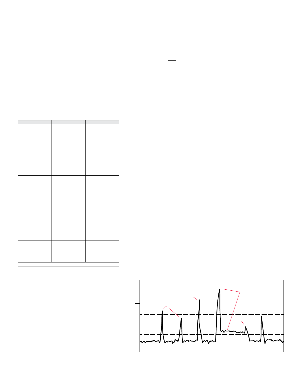
SETTING EMISSION LEVEL ALARMS
The PMT2 will provide a 4 to 20 mA signal based on the range selected at set up.
Alarms can be programmed in the PLC or control system based on the 4 to 20 mA
signal from the particulate transmitter.
It is suggested to set two alarm set points. One alarm set point to monitor the emission
spikes and the second alarm to detect an increase in the baseline.
The alarm monitoring the emission spikes should be set to identify changes in the
spikes caused by the cleaning cycles. As lters become worn, the spike’s height and
duration will increase. The emission spike frequency will also increase because the
lters will require more frequent cleaning as they wear out. If there is a continuous
output above the emission spike alarm, it is more than likely a lter has torn and should
be changed right away.
The baseline alarm should detect an increase in the baseline reading. The type of
dust collector and facility regulations will dictate where the baseline alarm has to be
set. Typically the baseline alarm should be set 4 to 5 times over the initial baseline
reading measurement when lters are rst installed. So, if the baseline is 10 pA the
base line alarm should be set between 40 pA and 50 pA. It is recommended to set a
time delay in the PLC or control panel alarm to prevent false alarms during cleaning
cycles. When the output signal from the PMT2 is continuously above baseline alarm
it is time to replace the lters. If the emission spikes have increased yet the baseline
remains unchanged, it’s an early indication that the lters are starting to wear out and
will need to be changed soon.
)
)
)
750 pA
Emission
500 pA
Baseline
Alarm
5 pA
Spikes caused
by cleaning
Increased spike
because of
filter wear
Figure 3: Typical Filter Emissions
Increased spike and
baseline because
of filter wear
Replaced
filters
AVERAGING SELECTION
The PMT2 offers a digital averaging function because of the irregular ow of particulates
and the spikes during cleaning cycles. There are ten options for averaging ranging
from 1 to 360 seconds. The digital averaging takes a running average of the readings
for the selected amount of time. This will dampen output spikes from particulate
uctuations that could trip alarm settings. It is important to select an averaging setting
that will allow the operator to see the cleaning cycles. It is recommended to monitor the
baseline trend and peak to peak trend between cleaning cycles.
ZERO CALIBRATION
Even though the PMT2 will come zeroed from the factory it is recommended to zero
the transmitter after installation to ensure the best accuracy. When zeroing the PMT2,
make sure the dust collector is shut down and there is no air ow in the duct, stack or
pipe the transmitter is monitoring. It is recommended to re-zero the PMT2 once every
12 months for optimal performance. Please check your local laws and regulations as
clean air standards may require zero calibration on a certain time schedule based
on application. There are two ways the PMT2 can be zeroed. The rst method is
with the zero button on the front of the transmitter. Press and hold the button for 3
seconds and the transmitter will begin zeroing. The second method is the remote zero.
Supply DC voltage as shown in Figure 4 across the zero terminals on the back of
the transmitter for at least 3 seconds for the transmitter to start zeroing. While the
transmitter is zeroing, the PMT2 will output about 3.5 mA. The zero function will take
approximately 3 minutes. When zeroing is complete the output will return to a normal
output signal and the transmitter is ready for operation.
Remote Zero
10 to 28 V
- +
Zero Switch
MAINTENANCE/REPAIR
Upon nal installation of the Series PMT2, no routine maintenance is required. The
Series PMT2 is not eld serviceable and should be returned if repair is needed. Field
repair should not be attempted and may void warranty.
WARRANTY/RETURN
Refer to “Terms and Conditions of Sales” in our catalog and on our website. Contact
customer service to receive a Return Goods Authorization number before shipping the
product back for repair. Be sure to include a brief description of the problem plus any
additional application notes.
Note: Do not zero the PMT2 while the dust collector is in operation.
Figure 4: Remote Zero and Zero Switch
Symptom Potential Source Corrective Action
High Output Loop Wiring Check for dirty or defective terminals,
Power Supply Check the output voltage of the power
Erratic Output Loop Wiring Check the output voltage of the power
Low or No Output Zeroing The PMT2 will output about 3.5 mA
Loop Wiring Check for intermittent shorts, open
Table 3: Troubleshooting
interconnecting pins or receptacles.
supply at the transmitter terminals. It
should be 9.5 to 28 VDC.
supply at the transmitter terminals. It
should be 9.5 to 28 VDC.
Check for intermittent shorts, open
circuits and multiple grounds.
Check the polarity at the signal
terminals.
while zeroing. Wait approximately 3
minutes and the 4 to 20 mA signal
should return to normal.
circuits and multiple grounds.
Check the polarity at the signal
terminals.
Check the loop impedance.
’
’
–––

DWYER INSTRUMENTS, INC.
P.O. BOX 373 • MICHIGAN CITY, INDIANA 46360, U.S.A.
Phone: 219/879-8000
Fax: 219/872-9057
www.dwyer-inst.com
e-mail: info@dwyermail.com
Partikeltransmitter Serie PMT2
2X 1/2˝(12,7 mm) NPT ODER M20
[15.88]
AUF BEIDEN SEITEN
[147.64]
®
Technische Daten – Installations- und Betriebsanleitung
Merkblatt PC-PMT2
GEWINDEMONTAGE
Sonde
LängeAin [mm]
3˝
3 [76.20]
5˝
5 [127.00]
10˝
10 [254.00]
15˝
15 [381.00]
20˝
20 [508.00]
30˝
30 [762.00]
36˝
36 [914.40]
MONTAGE TRI-CLAMP 1.5˝ (38 mm)
Sonde
LängeAin [mm]
3˝
3-1/2 [88.90]
5˝
5-1/2 [139.70]
10˝
10-1/2 [266.70]
15˝
15-1/2 [393.70]
20˝
20-1/2 [520.70]
30˝
30-1/2 [744.70]
36˝
36-1/2 [927.10]
Der Partikeltransmitter der SERIE PMT2 dient der Messung des Partikelausstoßes
von Entstaubern. Mittels einer direkt gekoppelten elektrostatischen
Induktionssensortechnologie überwacht der Transmitter einen pA-Strom, der entsteht,
wenn sich ein Partikel entlang der Sonde bewegt; das Signal beträgt je nach Stärke des
Partikels zwischen 4 und 20 mA. Der PMT2 bietet 6 Empndlichkeitsstufen, so dass der
Benutzer diejenige auswählen kann, die am besten zu seiner Anwendung passt. Auch
der Auswahlschalter für Messbereich und Tests kann auf ein Ausgabesignal von 4 mA
oder 20 mA eingestellt werden, wenn dies bei der Einrichtung oder Fehlerbehebung
hilfreich ist. Bei Bedarf lässt sich zur Dämpfung des Signals die Zeiteinstellung mitteln.
MERKMALE / VORZÜGE
• simple 2-Drahtmontage für SPS und Steuertafeln
• haftabweisende Sonde mit PTFE-Beschichtung gegen Falschmessungen an
feuchtem und leitfähigem Staub, Kondensat und Staubansammlungen
• durch Nullkalibrierung aus der Ferne verringert sich Wartungszeit
TABELLE
Beispiel PMT2 -05 -A -U2 PMT2-05-A-U2
Serie PMT2 Partikeltransmitter
Sondenlänge 03
Prozessanschluss A
Gehäuse A2U2ATEX und IECEx (IS)
Optionen STM2Kennzeichnung Edelstahl
*Optionen ohne ATEX- oder IECEx-Schutz
Achtung: Geräte ohne A2-Sufx sind nicht nach 2014/34/EC (ATEX) zertiziert.
Diese Geräte sind für den Einsatz in explosionsgefährdeten Räumen nicht
geeignet. Sie sind nur nach CE getestet.
05
10
15
20
30
36
B
C
B
in [mm]
1-25/32 [45.24]
3-25/32 [96.04]
8-25/32 [223.04]
13-25/32 [350.04]
18-25/32 [477.04]
28-25/32 [731.04]
34-25/32 [883.44]
Sondenlänge 3˝ (76.20 mm)
Sondenlänge 5˝ (127 mm)
Sondenlänge 10˝ (254 mm)
Sondenlänge 15˝ (381 mm)
Sondenlänge 20˝ (508 mm)
Sondenlänge 30˝ (762 mm)
Sondenlänge 36˝ (914 mm)
Außengewinde 3/4˝ (19 mm)
1.5˝ (38 mm)-Tri-clamp-Bausatz mit 1˝
(25 mm)-NPT-Außengewinde
3/4˝ (19 mm) BSPT-Gewinde
UL (IS)*
Sockel M20 elektrische Eingänge
(Sockel 1/2˝ (12.7 mm) NPT-
Standard)
5/8
Montage NPT-Außengewinde 3/4˝ (19 mm) ODER
ELECTRISCHER EINGANG
3/4˝ (19 mm) NPT oder
3/4˝ (19 mm) BSPT
“A”
3/4˝ (19 mm) Montage BSPT-Außengewinde
2X 1/2˝(12,7 mm) NPT ODER M20
ELECTRISCHER EINGANG
“B”
Montageoption Tri-Clamp 1.5˝ (38 mm)
3-29/32
[99.22]
3/4
[19.05]
1-1/2
[38.10]
1˝ (25 mm) NPT
“A”
TECHNISCHE DATEN
Wartung: Luft und kompatible Gase, alle Arten von Partikel leitend oder nicht
leitend.
Mediumberührende Teile: 316L SS, Silikon und PTFE.
Gehäuse: pulverbeschichtetes Aluminium.
Genauigkeit: ±5 % des Messwerts.
Partikelgröße: 0,3 Mikrometer und mehr.
Messbereich: 5 bis 5000 pA (6 auswählbare Messbereichsoptionen).
Temperaturbereich: Umgebungstemp.: -40 to 145 °F (-40 bis 63 °C);
Prozesstemp.: -40 bis 120 °F (-40 bis 248 °C).
Druckbereich: 30 bar (2 psi).
Signalausgabe: 4 bis 20 mA.
Leistungsbedarf: 12 bis 28 V Gleichstrom ( ).
Elektrischer Anschluss: Zwei 1/2˝ NPT-Außengewinde für elektrische Eingänge
oder zwei M20 elektrische Eingänge (A2 nur Sufx).
Klemmleiste: abnehmbar (Draht 16 bis 20 AWG).
Prozessanschluss: Siehe Tabelle. BSPT-Prozessanschlüsse sind nicht ULgelisted.
Sondenlängen: Siehe Tabelle.
Gehäuse: UL-Typ 4 (IP66) ATEX/IECEx IP65.
Montagerichtung: alle.
Mittelungszeit: 1 bis 360 s (10 auswählbare Optionen).
Gewicht: je nach Probenlänge und Art der Befestigung.
Zulassungen: CE, cULus; ATEX zertiziert: 0518 II 1 G Ex ia IIB T4 GA (-40°C
≤ Tamb ≤ 63°C) (-40°C ≤ T
(-40°C ≤ Tamb ≤ 63°C) (-40°C ≤ T
16ATEX1768 X. ATEX-Standards: EN 60079-0:2012/A11:2013; EN 60079-11:2012.
IECEx Zertiziert: Ex ia IIB T4 Ga (-40°C ≤ Tamb ≤ 63°C) (-40°C ≤ T
/ Ex ia IIIC T120°C Da (-40°C ≤ Tamb ≤ 63°C) (-40°C ≤ T
Konformitätszertikat: IECEx UL 16.013X. IECEx-Standards: IEC 60079-0: 2011;
IEC 60079-11: 2011. UL als eigensicher Klasse I, Gruppe C und D eingestuft;
Klasse II, Gruppe E, F und G; Klasse III; Klasse I Zone 0 AEx ia IIB T4 Ga; Klasse I
Zone 0 Ex ia IIB T4 Ga.
4-15/16
[125.41]
5-13/16
3-29/32
[99.22]
Prozess ≤ 120°C) / II 1 D Ex ia IIIC T120°C Da
Process ≤ 120°C). Zertikat Nr.: DEMKO
SPIELRAUM 1-1/4˝ (32 mm) [32]
FÜR ENTFERNUNG DER
ABDECKUNGEN
Prozess ≤ 120°C).
Prozess ≤ 120°C)
4-3/8
[111.13]
DWYER INSTRUMENTS, INC.
P.O. BOX 373 • MICHIGAN CITY, INDIANA 46360, USA
Tel.: +1 - 219/879-8000
Fax: +1 - 219/872-9057
www.dwyer-inst.com
E-Mail: info@dwyermail.com
FUNKTIONSPRINZIP
Technologie
Der PMT2 verwendet eine höchst verlässliche direkt gekoppelte elektrostatische
Induktionssensortechnologie. Dabei wird die Sensorsonde in einem Luftstrom montiert
wie beispielsweise einer Leitung, einem Rohr oder Schacht. Der induktive Effekt tritt ein,
wenn sich ein Partikel an einer Sonde entlang bewegt, so dass die Ladung vom Partikel
auf die Sonde übertragen wird. Dabei ltert ein Mikroprozessor das Signal und wandelt es
in ein Ausgabesignal um, das sich linear zur Massenkonzentration des Partikels verhält.
Die beschichtete PTFE-Sonde gewährleistet bei allen Partikeln einen verlässlichen
Betrieb, einschließlich Feuchtpulver und hochleitfähiger Stäube. Dank der
beschichteten PTFE-Sonde wird keine Sperrluft benötigt und die Wartung auf ein
Mindestmaß beschränkt.
Partikelüberwachung
Der PMT2 ist speziell zur durchgängigen Überwachung des Partikelgehalts in
Luftströmen aus Schächten und anderen Ausstoßstellen ausgelegt, die durch einen Filter
in einer Luftlteranlage geleitet werden. Der Transmitter sollte im Abluftkanal montiert
werden und kann in Verbindung mit verschiedenen Arten von Beutel-, Keramik-, Kerzenoder Zyklonltern verwendet werden. Bei der Erstmontage des PMT2 eine Messung der
Grundlinie vornehmen und den Wert festhalten. Dieser Messwert richtet sich nach der
Anwendung und muss bei jeder Installation einzeln ermittelt werden. Auf der Grundlage
dieses Werts überwacht der Bediener das Ausgabesignal des PMT2. Ein Anstieg beim
mA-Wert des Ausgangssignals deutet auf einen erhöhten Partikelgehalt im Luftstrom
hin, weil die Filter entweder abgenutzt oder defekt sind.
Der PMT2 ist für ein proportionales Ausgabesignal auf der Grundlage des Partikelpegels
in Rohren und Leitungen ausgelegt, nicht jedoch für ein Ausgabesignal auf der Grundlage
des Partikelvolumenstroms. Verschiedene Partikelarten transportieren unterschiedliche
Ladungen, so dass zwei Partikel, die sich mit derselben Durchussgeschwindigkeit
bewegen, zwei verschiedene Ausgabesignale erzeugen können. Der PMT2 wurde
dazu entwickelt, unter idealen Betriebsbedingungen eine Grundlinie zu nden und
dem Bediener die Möglichkeit zu geben, das Ausgangssignal auf einen Anstieg zu
kontrollieren, die darauf hinweist, dass die Beutel oder Filter sich allmählich abnutzen
oder Schäden aufweisen. Durch die sechs Empndlicheitsstufen lassen sich mit dem
PMT2 sowohl Partikel mit niedriger als auch mit hoher Ladung überwachen. Zur
Orientierung sind in Tabelle 1 die Ladungseigenschaften und die empfohlenen Stufen
aufgeführt.
MONTAGE
Auspacken
Den PMT2 aus dem Versandkarton nehmen und auf Schäden untersuchen. Bei
eventuellen Schäden den Spediteur umgehend in Kenntnis setzen.
Montagestelle
Bei der Auswahl der Stelle, an der der PMT2 installiert werden soll, sind folgende
Punkte zu beachten:
• Darauf achten, dass der Transmitter für die Umgebung eingestuft ist, in der er
montiert werden soll.
• Den Transmitter an einer Stelle montieren, an der die in den technischen Daten
aufgeführten Temperatur- und Druckwerte nicht überschritten werden. Der
Prozessdruck darf 2 Bar (30 psi) nicht überschreiten.
• Darauf achten, dass die Signalkabel für 4 bis 20 mA nicht durch die gleiche Leitung
verlaufen wie die Starkstromkabel.
• Darauf achten, dass die Stelle, an der der Transmitter angebracht wird, den NEMAoder IP-Betriebswert für das Gehäuse erfüllt.
• Den Transmitter an einer Stelle anbringen, wo er im Wartungsfall erreichbar ist.
Der PMT2 sollte in einem geerdeten Metallschacht, -rohr oder einer geerdeten
Metallleitung montiert werden. Nicht an Schächten, Rohren oder Leitungen aus
Glasfaser oder Kunststoff anbringen. Zur Gewährleistung einer genauen Messung
muss die Sonde 1/2 bis 2/3 über den Schacht, das Rohr oder die Leitung reichen.
Am stabilsten und genausten sind die Messwerte, wenn der PMT2 an einer Stelle
montiert wird, an der der Luftstrom möglichst laminar ist. Den Transmitter möglichst
nicht in der Nähe von Ventilatoren und Luftklappen montieren, die Turbulenzen
verursachen. Idealerweise sollte der PMT2 in einem Bereich mit zwei vorgelagerten
Rohrdurchmessern und einem nachgelagerten Rohrdurchmesser montiert werden,
die frei von Turbulenzen hervorrufenden Gegenständen sind. Die Sensorsonde ist mit
einem haftabweisenden PTFE beschichtet, so dass kein Material an der Sonde haften
bleibt, wodurch sich der Reinigungs- und Luftspülaufwand verringert.
neutral
Partikel Empfohlene Stufe
Menschenhände
Asbest
Kaninchenfell
Azetat
Glas
Glimmer
Menschenhaar
Nylon
positivnegativ
Holz
Fell
Blei
Seide
Aluminium
Papier
Baumwolle
Stahl
Holz
Mylar™
Nickel / Kupfer
Silber / Messing
Gold / Platin
Schwefel
Azetatseide
Polyester
Styren (Styropor)
Acryl
Saran™
Polyurethan
Polyethylen
Polypropylen
Vinyl (PVC)
Silikon
PTFE
Silikonkautschuk
Tabelle 1: empfohlene Stufen
5 bis 5000 pA
5 bis 1000 pA
5 bis 500 pA
5 bis 100 pA
5 bis 500 pA
5 bis 1000 pA
5 bis 5000 pA

VERKABELUNG
E
NULLABGLEICH
AUS DER FERN
ACHTUNG
• Bei Montage und Wartung des Geräts die Netzspannung
stets ausschalten und bei Bedarf den Sperrschalter betätigen
• Bei Leitungs- und Lastanschlüssen nur Draht mit 16 bis 20 AWG verwenden. Bei
der Montage die vor Ort geltenden Vorschriften und Gesetze wie den National Electric
Code beachten.
• Schutzstufe TYPE 4 (IP66) ist gewährleistet, wenn passende Anschlüsse und
Stecker gemeinsam mit UL-gelisteten Modellen verwendet werden.
WARNHINWEIS
GEFAHRENSTELLEN
Damit sich Gefahrenstellen nicht entzünden, sind
folgende Vorkehrungen zu treffen:
• Geräteabdeckungen während des Betriebs fest geschlossen halten.
• Vor dem Öffnen der Geräteabdeckung die Stromversorgung ausschalten.
• Vor dem erneuten Einschalten der Stromversorgung die Geräteabdeckungen wieder
aufsetzen.
• Das Gerät lässt sich nicht vor Ort reparieren und muss deshalb im Reparaturfall an
Dwyer Instruments geschickt werden.
WARNHINWEIS
SPEZIFISCHE NUTZUNGSBEDINGUNGEN BEZÜGLICH
EIGENSICHERHEIT
Zur Aufrechterhaltung der Eigensicherheit sind folgende
Vorsichtsmaßnahmen zu ergreifen:
• Signal von 4-20 mA und der Nullabgleich aus der Fernen müssen als zwei getrennte
Schaltkreise behandelt werden.
• Die Bauteile des Gehäuses bestehen aus Aluminum. Das Gehäuse muss vor
Brandgefahr durch Stoßeinwirkung oder Reibung geschützt werden.
• Alle Gehäuseöffnungen müssen mit passenden Anschlüssen und Steckern
abgedichtet sein, die mindestens der IP-Schutzklasse IP66 für UL-gelistete Modelle
und IP65 für ATEX/IECEz zertizierte Modelle entsprechen.
• Durch den Austausch von Bauteilen wird die Eigensicherheit gefährdet.
STEUERPLAN UL-GELISTETE EIGENSICHERHEIT (ENDUNG U2):
UL als eigensicher eingestuft für Gebrauch in Klasse I Unterklasse 1 Gruppe C und D; Klasse
II Unterklasse 1 Gruppe E, F und G; Klasse III Unterklasse. 1; Klasse I Zone 0 AEx ia IIB T4
Ga; Klasse I Zone 0 Ex ia IIB T4 Ga; T4@63°C, sofern Installation in Übereinstimmung mit
Steuerplan 001744-48 auf Seite 6 des vorliegenden Dokuments erfolgt ist.
ATEX ZERIFIZIERT (SUFFIX A2)
II 1 G Ex ia IIB T4 Ga (-40°C ≤ Tamb ≤ 63°C) (-40°C ≤ T
IIIC T120°C Da (-40°C ≤ Tamb ≤ 63°C) (-40°C ≤ T
Process ≤ 120°C) / II 1 D Ex ia
Process ≤ 120°C), sofern Installation in
Übereinstimmung mit Steuerplan 001744-81 auf Seite 7 dieses Dokuments erfolgt ist.
IECEx ZERIFIZIERT (SUFFIX A2)
Ex ia IIB T4 Ga (-40°C ≤ Tamb ≤ 63°C) (-40°C ≤ T
T120°C Da (-40°C ≤ Tamb ≤ 63°C) (-40°C ≤ T
Process ≤ 120°C) / Ex ia IIIC
Process ≤ 120°C), sofern Installation in
Übereinstimmung mit Steuerplan 001744-81 auf Seite 7 dieses Dokuments erfolgt ist.
EINGABEPARAMETER EIGENSICHERHEIT:
Signal 4-20 mA, Vmax (Ui) = 28 V; Imax (li) = 93 mA; Ci = .022 μF; Li = 0.373 mH;
Pmax (Pi) = 651 mW
Nullabgleich aus der Ferne, Vmax (Ui) = 28 V; Imax (li) = 93 mA; Ci = vernachlässigbar;
Li = 0 mH; Pmax (Pi) = 651 mW
LEISTUNGSBEDARF
Die maximale Netzspannung beträgt 28 V Gleichstrom. Die erforderliche
Gleichstromversorgung basiert auf folgenden Werten:
1. Minimale Gleichspannung für Modell PMT2.
2. Gesamtlastwiderstand.
3. Gesamtwiderstand der Anschlussleitung.
4. Spannungsabfall Zener-Schranke (nur Modell PMT2-XX-X-X2).
Die Formel zur Berechnung der Gleichstromversorgung lautet:
V (Gleichstrom) = VPMT2 + VLOAD + VLEADWIRE + VBARRIER
wobei VPMT2 = 9,5 V
VLOAD = Gesamtlastwiderstand X 20 mA
VLEADWIRE = Gesamtwiderstand der Anschlussleitung X 20 mA
VBARRIER = 8.1 V (bei dieser Anwendung typischer Spannungsabfall bei Zener-
Schranke)
Beispiel 1: Minimale Gleichstromversorgung für eigensichere Modelle
berechnen
Schritt 1 VPMT2 = 9,5 V
Schritt 2 VLOAD berechnen. Dabei Umrechnungswiderstand der Branchennorm
von 250 Ω, VLOAD = 250 X 20 mA = 5 V verwenden.
Schritt 3 VLEADWIRE berechnen. Für dieses Beispiel ausgehen von einem
Gesamtwiderstand der Anschlussleitung von 10 Ω, VLEADWIRE = 10 X
20 mA = 0.2 V
Schritt 4 VBARRIER = 8.1 V
Schritt 5 VDC = VPMT2 + VLOAD + VLEADWIRE + VBARRIER = 9.5 + 5 + 0.2 +
8.1 = 22.8 V
STEUERELEMENTE
WARNHINWEIS
WARTUNG BEI LAUFENDEM BETRIEB
Bei Vorliegen einer entzündlichen oder ammbaren Atmosphäre
dürfen keine Wartungsarbeiten an Nullabgleich, Mittelungszeit,
Stufen und Teststeuerungen bei laufendem Betrieb vorgenommen werden.
Nullschalter (siehe Abbildung 2)
Den Schalter 3 lang gedrückt halten, so dass sich der PMT2 einen digitalen Nullabgleich
durchführt. Nach einem Funktionsausfall oder Austausch des Filters empehlt sich ein
erneuter Nullabgleich. Einen erneuten Nullabgleich nur dann durchführen, wenn keine
Luft durch die Leitung strömt.
Auswahlschalter Mittelungszeit
Der PMT2 mittelt das Ausgangssignal über den angegebenen Zeitraum. So werden
Spitzen ausgeglichen, die beim normalen Filterreinigungszyklus auftreten.
Auswahlschalter Stufen und Test
Je nach aufzuspürendem Material stehen bei der Messung mit dem 6 PMT2
Empndlichkeitsstufen zur Auswahl (siehe Tabelle 1). Ferner gibt es die Option eines
Ausgabesignals von 4 mA oder 20 mA, welche bei der Montage des Transmitters und
bei der Fehlerbehebung hilfreich sein können.
RECEIVER
SCHALTER FÜR NULLABGLEICH AUS DER FERN
(WENN VERWENDET)
4 bis 20 mA.
4
3
2
1
E
Abbildung 1: allgemeine Montageverkabelung (nicht IS)
NETZVERSORGUNG
Mittelungszeit
Erdungsschraube
Abbildung 2
Nullschalter
Stufen und
Tes ts

ENRICHTUNG
1000 pA
Emissionsspitzenalar
Montage
Damit es während des Betriebs nicht zu Vibrationen kommt, darauf achten, dass der
PMT2 fest am Schacht, Rohr oder an der Leitung angebracht ist. Dafür sorgen, dass
der Transmitter korrekt geerdet ist.
Einrichtung des Steuersignals
Verkabelung der Stromversorgung auf korrekte Polarität kontrollieren, bevor Sie die
Stromzufuhr zum PMT2 einschalten. Die Stromzufuhr zum Transmitter einschalten
und den Auswahlschalter für Stufen und Tests auf 4 mA (Position 2) stellen. Das
Ausgabesignal des PMT beträgt normalerweise 4 mA; das Ausgabesignal mit
Mehrfachmessgerät oder an dem Gerät kontrollieren (SPS, Anzeige usw.), das das
Ausgabesignal empfängt. Sobal der Empfang des Signals von 4 mA bestätigt ist,
den Auswahlschalter für die Stufen und Tests auf 20 mA (Position 1) stellen und den
Vorgang wiederholen. Bei einem Signal von 0 mA kontrollieren, ob die Stromversorgung
eingschaltet ist und eventuell Drähte locker sitzen.
LOGARITHMISCHE STUFE
Bei den logarithmischen Stufen ist das untere Ende des Skala verlängert und das
obere Ende komprimiert. So hat der Bediener die Möglichkeit, die Grundlinie
in einer besseren Auösung zu überwachen und gleichzeitig die Spitzen beim
Reinigungszyklus im Auge zu behalten. Die logarithmischen Stufen empfehlen sich
bei Filterbeuteln, da diese eine größere Wahrscheinlichkeit von Partikelspitzen bei der
Reingung aufweisen.
BERECHNUNGEN LOGARITHMISCHE STUFE
(M-4)
pA = 10 x R + 0,699
(
16
pA = gemessene Pikoampere (pA)
M = am PMT2 gemessene Milliampere (mA)
R = 2 (für logarithmische Stufe 5 bis 500 pA)
R = 3 (für logarithmische Stufe 5 bis 5000 pA)
)
Auswahl von Stufen und Tests
Bei Auswahl einer der 6 verfügbaren Stufen müssen die Grundlinie und die maximalen
Spitzensignale beachtet werden, die während der Filterreinigung auftreten. Die
ausgewählte Stufe muss eine ausreichende Auösung aufweisen, um die Grundlinie zu
überwachen und die maximale Spitze bei einem Reinigungszyklus zu erfassen. Die vier
linearen Stufen entsprechen einem Ausgangssignal von 4 mA bei 5 pA und 20 mA auf
der Höchststufe. Die zwei logarithmischen Stufen verfügen über eine feinere Auösung
am niedrigeren Ende der Stufe und weniger am höheren Ende.
Schalterposition Stufe Signalausgabe
1 Test 20 mA
2 Test 4 mA
3 5 bis 100 pA 5 pA = 4 mA
4 5 bis 500 pA 5 pA = 4 mA
5 5 bis 1000 pA 5 pA = 4 mA
6 5 bis 5000 pA 5 pA = 4 mA
7 Log 5 bis 500 pA 5 pA = 4 mA
8 Log 5 bis 5000 pA 5 pA = 4 mA
Hinweis: Position 9 und 0 sind ungenutzt.
Tabelle 2: Auswahlschalter Stufen und Test
25 pA = 8 mA
50 pA = 12 mA
75 pA = 16 mA
100 pA = 20 mA
125 pA = 8 mA
250 pA = 12 mA
375 pA = 16 mA
500 pA = 20 mA
250 pA = 8 mA
500 pA = 12 mA
750 pA = 16 mA
1000 pA = 20 mA
1250 pA = 8 mA
250 pA = 12 mA
3750 pA = 16 mA
5000 pA = 20 mA
16 pA = 8 mA
50 pA = 12 mA
158 pA = 16 mA
500 pA = 20 mA
28 pA = 8 mA
158 pA = 12 mA
890 pA = 16 mA
5000 pA = 20 mA
750 pA
Beispiel 1: Logarithmischer Bereich von 5 bis 500 pA bei Ausgangsstrom von 12 mA:
(12-4)
pA = 10 x 2 + 0,699
(
16
pA = 50
Beispiel 2: Logarithmischer Bereich von 5 bis 5000 pA bei Ausgangsstrom von 14 mA:
(14-4)
pA = 10 x 3 + 0,699
(
16
pA = 375
EINSTELLUNG DER EMISSIONSPEGELALARME
Der PMT2 stellt ein Signal zwischen 4 und 20 mA bereit, je nachdem, welche
Stufe bei der Einrichtung ausgewählt wurde. Alarme können in einer SPS oder
Steuerungsanlage auf der Grundlage des Signals von 4 bis 20 mA aus dem
Partikeltransmitter programmiert werden.
Es empehlt sich, zwei Alarmsollwerte einzustellen. Dabei überwacht ein Sollwert die
Emissionsspitzen und der zweite den Anstieg der Grundlinie.
Der Alarm zur Überwachung der Emissionsspitzen sollte so eingestellt sein, dass er
Änderungen bei den Spitzen erfasst, die durch die Reinigungszyklen entstehen. Bei
Abnutzung der Filter nehmen Höhe und Dauer der Spitzen zu. Auch die Häugkeit der
Emissionsspitzen wird größer, da die Filter bei Abnutzung häuger gereinigt werden
müssen. Liegt die Signalausgabe durchgehend oberhalb des Emissionsspitzenalarms,
ist der Filter höchstwahrscheinlich defekt und sollte umgehend ausgetauscht werden.
Der Grundlinienalarm misst wahrscheinlich einen Anstieg des Grundlinienwerts. Wo
der Grundlinienalarm eingestellt wird, richtet sich nach der Art des Staublters und
nach den Vorschriften der Einrichtung. Normalerweise wird bei der Erstinstallation
der Filter der Grundlinienalarm beim 4- bis 5-Fachen des zuerst gemessenen
Grundlinienwerts eingestellt. Beträgt also die Grundlinie 10 pA, ist der Grundlinienalarm
auf 40 pA bis 50 pA einzustellen. Damit während der Reinigungszyklen kein falscher
Alarm ausgelöst wird, empehlt es sich, in der SPS oder der Steuerstafel eine
Zeitverzögerung einzustellen. Wenn das Ausgangssignal des PMT2 durchgängig über
dem Grundlinienalarm liegt, ist es Zeit für einen Filterwechsel. Eine Zunahme der
Emissionsspitzen bei gleichzeitig unveränderter Grundlinie deutet darauf hin, dass die
Filter sich allmählich abnutzen und bald ausgewechselt werden müssen.
Spannungsspitze
durch Reinigung
)
)
höhere Spannungsspitze
durch Filterabnutzung
höhere Spannungsspitze
und Grundlinie durch
Filterabnutzung
500 pA
Grundlinienalarm
5 pA
m
Filteraustausch
ZEITVERLAUF
Abbildung 3: Typische Filteremissionen

MITTELUNGSAUSWAHL
Aufgrund des unregelmäßigen Partikelstroms und der Spitzen während der
Reinigungszyklen bietet der PMT2 eine digitale Mittelungsfunktion. Zur Mittelung stehen
zehn Optionen zwischen 1 und 360 Sekunden bereit. Mit der digitalen Mittelungsfunktion
wird über den angegebenen Zeitraum der laufende Durchschnitt der Messwerte ermittelt.
So werden Spitzen ausgeglichen, die infolge von Partikelschwankungen auftreten und
den Alarm auslösen können. Dabei ist es wichtig, die Mittelung so einzustellen, dass der
Bediener die Reinigungszyklen sehen kann. Zwischen den Reinigungszyklen empehlt es
sich, die Bewegung der Grundlinie und die Tendenz zwischen den Spitzen zu überwachen.
NULLKALIBRIERUNG
Zwar wird der PMT2 kalibriert geliefert; dennoch empehlt es sich, nach der Montage
einen Nullabgleich vorzunehmen, um eine optimale Genauigkeit zu gewährleisten.
Beim Nullabgleich des PMT2 sicherstellen, dass der Staublter ausgeschaltet ist und
keine Luft durch die zu überwachende Leitung, das Rohr oder den Schacht strömt.
Zwecks optimaler Leistung den PMT2 einmal alle 12 erneut kalibrieren. Bitte die vor Ort
geltenden Gesetze und Vorschriften beachten, da je nach Anwendung möglicherweise
Nullkalibrierungen nach einem bestimmten Zeitplan erfolgen müssen. Der Nullabgleich
am PMT2 kann auf zwei Arten vorgenommen werden. Die erste Möglichkeit ist der
Nullschalter vorn am Transmitter. Dazu den Schalter 3 lang gedrückt halten, so dass der
Transmitter einen Nullabgleich durchführt. Die zweite Methode ist der Nullabgleich aus
der Ferne. Wie in Abbildung 4 die Nullklemmleisten auf der Rückseite des Transmitters
mindestens 3 Sekunden mit Gleichstrom versorgen, so dass der Transmitter mit dem
Nullabgleich beginnt. Während des Nullabgleichs gibt der PMT2 ein Signal von circa
3,5 mA aus. Der Nullabgleich dauert circa 3 Minuten. Nach Abschluss des Nullabgleichs
normalisiert sich das Ausgangssignal, und der Transmitter ist einsatzbereit.
Nullabgleich aus der Ferne
10 bis 28 V
WARTUNG / REPARATUR
Im Anschluss an die Montage der Serie PMT2 ist keine Routinewartung erforderlich.
Die Serie PMT2 lässt sich nicht vor Ort warten und muss deshalb im Reparaturfall
eingeschickt werden. Keine Reparatur vor Ort vornehmen, da dadurch die
Gewährleistung aufgehoben wird.
GEWÄHRLEISTUNG / EINSENDUNG
Siehe „Allgemeine Vertriebsbedingungen“ in unserem Katalog und auf der Website.
Bevor Sie das Produkt zur Reparatur einschicken, holen Sie sich bitte beim
Kundendienst eine Warenrücksendenummer. Fügen Sie außerdem eine kurze
Erläuterung des Problems sowie zusätzliche Anmerkungen bei.
- +
Anmerkung: Keinen Nullabgleich des PMT2 durchführen, wenn der Staublter in
Abbildung 4: Nullabgleich aus der Ferne und Nullschalter
Symptom Mögliche Ursache Korrekturmaßnahme
Hohes Signal Verkabelung Anschlussklemmen, Verbindungsstifte
Netzversorgung Die Ausgangsspannung der
Unregelmäßiges
Signalausgabe
Geringes oder kein
Ausgabesignal
Verkabelung Die Ausgangsspannung der
Nullstellung Während des Nullabgleichs gibt der
Verkabelung Auf zwischenzeitliche Kurzschlüsse,
Betrieb ist.
und Steckdosen auf Schmutz und
Defekte kontrollieren.
Stromversorgung an den Klemmleisten
des Transmitters kontrollieren.
Sie muss zwischen 9,5 und 28 V
(Gleichstrom) betragen.
Stromversorgung an den Klemmleisten
des Transmitters kontrollieren.
Sie muss zwischen 9,5 und 28 V
(Gleichstrom) betragen.
Auf zwischenzeitliche Kurzschlüsse,
offene Schaltkreise und
Mehrfacherdung untersuchen.
Polarität der Signalanschlussklemmen
prüfen.
PMT2 ein Signal von circa 3,5 mA aus.
Circa 3 Minuten warten, bis das Signal
wieder in ein normales Signal ausgibt,
d.h. zwischen 4 und 20 mA.
offene Schaltkreise und
Mehrfacherdung untersuchen.
Polarität der Signalanschlussklemmen
prüfen.
Schleifenwiderstand kontrollieren.
Tabelle 3: Fehlerbehebung
Nullschalter

’
’
–––
DWYER INSTRUMENTS, INC.
P.O. BOX 373 • MICHIGAN CITY, INDIANA 46360, USA
Tel.: +1 - 219/879-8000
Fax: +1 - 219/872-9057
www.dwyer-inst.com
E-Mail: info@dwyermail.com

Sonde-émetteur à particules série PMT2
2X ENTRÉE ÉLECTRIQUE 1/2 po (12,7 mm)
[15.88]
DU COUVERCLE
®
Spécications - Installation et mode d'emploi
Bulletin PC-PMT2
La sonde-émetteur à particules SÉRIE PMT2 est prévu pour mesurer les taux
d'émission de particules à la sortie des ltres à poussière. La sonde-émetteur utilise
une technologie de détection à induction électrostatique couplée en CC pour mesurer
un courant en pA généré lorsque les particules passent à proximité de la sonde ; un
signal entre 4 et 20 mA varie selon le taux de particules. Le PMT2 propose 6 plages
de sensibilité pour permettre à l'utilisateur de choisir la plage qui correspond le mieux
à son utilisation. Le sélecteur de plage et de test peut également être positionné pour
envoyer un signal de 4 mA ou 20 mA pour aider au paramétrage ou à la recherche
de panne. Le paramétrage du calcul de temps moyen peut être utilisé pour lisser le
signal si nécessaire.
FONCTIONNALITÉS/AVANTAGES
• Installation simple à 2 câbles pour le PLC et les panneaux de contrôle.
• Une sonde recouverte de PTFE antiadhésif pour éviter les lectures faussées à cause
de l'humidité et des poussières conductrices, la condensation et l'accumulation de
poussière,
• La réinitialisation à distance permet de réduire le temps de maintenance
TABLEAU DU MODÈLE
Exemple PMT2 -05 -A -U2 PMT2-05-A-U2
Séries PMT2 Émetteur-sonde à particules
Longueur de sonde 03
Processus de
raccordement
Indice de protection
du boîtier
Options STM2Etiquette en acier inoxydable
* Options qui ne sont pas homologuées ATEX ou IECEx.
Attention : Les unités qui ne comportent pas le marquage A2 ne satisfont pas aux
exigences de la Directive 2014/34/EC (ATEX). Ces unités ne sont pas conçues
pour une utilisation en atmosphère potentiellement dangereuses au sein de l'Union
Européenne. Ces unités peuvent être estampillées CE pour d'autres Directives de
l'Union Européenne.
BAGUE DE
RACCORDEMENT FILETÉE
Sonde
LongueurApo [mm]
3 po
5 po
10 po
15 po
20 po
30 po
36 po
BAGUE DE RACCORDEMENT À TROIS
BROCHES 1,5 po (38 mm)
Sonde
LongueurApo [mm]
3 po
5 po
10 po
15 po
20 po
30 po
36 po
05
10
15
20
30
36
A
B
C
A2
U2
3 [76.20]
5 [127.00]
10 [254.00]
15 [381.00]
20 [508.00]
30 [762.00]
36 [914.40]
B
3-1/2 [88.90]
5-1/2 [139.70]
10-1/2 [266.70]
15-1/2 [393.70]
20-1/2 [520.70]
30-1/2 [744.70]
36-1/2 [927.10]
3 po (76.20 mm) longueur de sonde
5 po (127 mm) longueur de sonde
10 po (254 mm) longueur de sonde
15 po (381 mm) longueur de sonde
20 po (508 mm) longueur de sonde
30 po (762 mm) longueur de sonde
36 po (914 mm) longueur de sonde
Raccord mâle NPT 3/4 po (19 mm)
Kit trois broches 1,5 po (38 mm) avec
raccord mâle NPT 1 po (25 mm)
Raccord mâle NPT 3/4 po (19 mm)
ATEX et IECEx (IS)
UL (IS)*
Entrées électriques femelles M20
(femelle 1/2 po (12,7 mm) NPT standard)
po [mm]
1-25/32 [45.24]
3-25/32 [96.04]
8-25/32 [223.04]
13-25/32 [350.04]
18-25/32 [477.04]
28-25/32 [731.04]
34-25/32 [883.44]
NPT OU M20
NPT 3/4 po (19 mm) ou
BSPT 3/4 po (19 mm)
5/8
Bague de raccordement mâle NPT 3/4 po
2X ENTRÉE ÉLECTRIQUE 1/2 po (12,7 mm)
NPT OU M20
“A”
(19 mm) ou mâle BSPT 3/4 po (19 mm)
“B”
“A”
Bague de raccordement à trois broches
1,5 po (38 mm)
SPÉCIFICATIONS
Service : Air et gaz compatibles, tout type de particules conductrices ou nonconductrices.
Matériaux mouillés : 316L SS, silicone, et PTFE.
Boîtier : Aluminium recouvert d'une couche conductrice.
Précision : ±5% du résultat.
Taille des particules : 0,3 microns et plus.
Plage de détection : 5 à 5000 pA (6 options de plage possibles).
Limites de température : ambiante : -40 à 145°F (-40 à 63°C) ; en fonction : -40 à
248°F (-40 à 120°C).
Limite de pression : 2 psi (30 bar).
SIgnal en sortie : 4 à 20 mA.
Puissance électrique nécessaire : 12 à 28 VCC ( ).
Raccordement électrique : Deux entrés électriques femelles 1/2 po (12,7 mm)
NPT ou deux entrées électriques M20 (marquage A2 uniquement).
Bornier : Amovible (câble de 16 à 20 AWG).
Processus de raccordement : Voir le tableau du modèle. Les processus de
raccordement BSPT ne sont pas enregistrés UL.
Longueurs de sonde : Voir le tableau du modèle.
Indice de protection du boîtier : UL Type 4 (IP66) ATEX/IECEx IP65.
Orientation de montage : Indifférente.
Durée moyenne : 1 à 360 s (10 options possibles).
Poids : Variable selon la longueur de la sonde et le type de raccord.
Homologations : CE, cULus; conforme ATEX: 0518 II 1 G Ex ia IIB T4 GA
(-40°C ≤ Tamb ≤ 63°C) (-40°C ≤ T
(-40°C ≤ Tamb ≤ 63°C) (-40°C ≤ T
16ATEX1768 X. Normes ATEX : EN 60079-0:2012/A11:2013; EN 60079-11:2012.
Certié IECEx : Ex ia IIB T4 Ga (-40°C ≤ Tamb ≤ 63°C) (-40°C ≤ T
Ex ia IIIC T120°C Da (-40°C ≤ Tamb ≤ 63°C) (-40°C ≤ T
Certicat de conformité : IECEx UL 16.013X. Normes IECEx : IEC 60079-0: 2011;
IEC 60079-11: 2011. Enregistré UL comme intrinsèquement sûr pour la classe I,
groupes C et D ; la classe II, groupes E, F et G ; la classe III ; la classe I zone 0
AEx ia IIB T4 Ga ; la classe I zone 0 Ex ia IIB T4 Ga.
[19.05]
1-1/2
[38.10]
1 po (25 mm)
NPT
3/4
5-13/16
[147.64]
4-15/16
[125.41]
3-29/32
[99.22]
3-29/32
[99.22]
Process ≤ 120°C) / II 1 D Ex ia IIIC T120°C Da
Process ≤ 120°C). Certicat n° : DEMKO
PRÉVOIR 1-1/4 po (32 mm) [32]
POUR LE RETRAIT
DES DEUX CÔTÉS
Process ≤ 120°C).
Process ≤ 120°C) /
4-3/8
[111.13]
DWYER INSTRUMENTS, INC.
P.O. BOX 373 • MICHIGAN CITY, INDIANA 46360, États-Unis.
Téléphone : +1 219/879-8000
Fax : +1 219/872-9057
www.dwyer-inst.com
courriel : info@dwyermail.com

PRINCIPE DE FONCTIONNEMENT
Technologie
Le PMT2 utilise une technologie de détection à induction électrostatique couplée
en CC extrêmement able. La sonde de détection est installée sur un passage d'air
comme un tuyau, une conduite ou cheminée. L'effet d'induction se produit lorsque des
particules passent à proximité de la sonde transférant une charge de la particule à la
sonde. Un microprocesseur ltre et traite le signal pour renvoyer un résultat linéaire de
la concentration globale en particules.
La sonde recouverte de PTFE garanti un fonctionnement able avec tous les types de
particules y compris les poudres humides et les poussières hautement conductrices. La sonde
recouverte de PTFE élimine la nécessité de purge d'air et permet une maintenance minimum.
Surveillance des particules
Le PMT2 est spécialement conçu pour surveiller les niveaux de particules en continu
dans le ux d'air des cheminées ou autres points d'émission après le passage à travers
le ltre d'un système de ltration de l'air. L'émetteur doit être installé dans le conduit
d'évacuation et peut être utilisé conjointement avec différent types de ltres à sac,
céramique, à cartouche ou cyclonique. Lors de la première installation du PMT2 une
mesure du niveau de référence moyen doit être effectuée et enregistrée. Cette mesure
du niveau de référence dépend de l'utilisation et doit être mesurée indépendamment
pour chaque installation. L'opérateur surveillera le signal en sortie du PMT2 par rapport
à ce niveau de référence. L'élévation du signal en mA indique un niveau de particules
en augmentation dans le ux d'air qui signie que les ltres sont soit usagés soit brisés.
Le PMT2 est prévu pour donner un signal proportionnel basé sur le niveau de particules
dans une conduite ou un tuyau, it n'est pas prévu pour sortir un signal basé sur le ux
volumétrique de particules. Les différents types de particules transportent différentes
charges, ce qui signie que deux particules transportées au même débit volumétrique
pourraient donner lieu à un signal différent. Le PMT2 est prévu pour identier un niveau
de référence dans les conditions de fonctionnement idéales et permettre à l'opérateur
de surveiller les hausses du signal en sortie qui signieraient que les sacs ou les ltres
commencent à se dégrader ou à se briser. Les six plages de sensibilité permettent au PMT2
de surveiller aussi bien des particules à charge basse que des particules à charge haute.
Á titre de référence, le tableau 1 liste les charges des particules et les plages suggérées.
INSTALLATION
Déballage
Retirer le PMT2 de son carton de transport et vérier l'absence de dommage. En cas
de dommage, informez immédiatement le transporteur.
Emplacement
Les facteurs suivant doivent être pris en compte pour déterminer l'emplacement de
l'installation du PMT2 :
• Vérier que l'émetteur est adapté pour la classication de la zone où il sera installé.
• Installer l'émetteur à un emplacement qui ne dépassera pas les niveaux de
température et de pression gurant dans les caractéristiques. La pression en
fonctionnement ne doit pas dépasser 30 psi (2 bar)
• Vérier que les câbles de 4 à 20 mA ne sont pas installés dans la même gaine que
les câbles haute tension.
• Vérier que l'emplacement où l'émetteur est installé est conforme aux niveaux
NEMA et IP pour le boîtier.
• Installer l'émetteur à un endroit où il peut être facilement accessible si un entretien
est nécessaire
Le PMT2 doit être monté dans une cheminée , un tuyau ou une conduite métallique
stabilisé. Il ne doit pas être monté sur des cheminées, tuyaux ou conduites en
plastique ou en bre de verre. La sonde de détection doit se situer entre 1/2 et 2/3
de la longueur de la cheminée, tuyau ou conduite pour assurer des résultats précis.
Pour les résultats les plus ables possibles il est recommandé d'installer le PMT2
dans un endroit où le ux d'air est aussi laminaire que possible. Eviter de monter
l'émetteur à proximité de souferies et de régulateurs qui causent des turbulences.
Idéalement, monter le PMT2 dans une zone avec deux diamètres de conduite de ux
montant et un diamètre de conduite de ux descendant, libres de tout objet pouvant
causer des turbulences. La sonde de détection est en PTFE antiadhésif pour éviter
que des matières ne recouvrent la sonde, réduisant la nécessité de nettoyage ou de
purge d'air.
Neutre
Particules Plage suggérée
Mains humaines
Amiante
Fourrure de lapin
Acétate
Verre
Mica
Poils humains
Nylon
PositifNégatif
Bois
Fourrure
Plomb
Soie
Aluminium
Papier
Coton
Acier
Bois
Mylar™
Nickel/cuivre
Argent/laiton
Or/platine
Souffre
Acétate de cellulose
Polyester
Styrène (mousse de
polystyrène)
Acrylique
Saran™
Polyuréthane
Polyéthylène
Polypropylène
Vinyle (PVC)
Silicone
PTFE
Gomme de silicone
Tableau 1 : plages suggérées
5 à 5000 pA
5 à 1000 pA
5 à 500 pA
5 à 100 pA
5 à 500 pA
5 à 1000 pA
5 à 5000 pA

CÂBLAGE
ANCE
RÉINITIALISA
À DIST
AVIS
• Toujours installer ou entretenir le dispositif en position hors
tension et installer un verrou de déconnection si nécessaire
• Utiliser uniquement des câbles en cuivre de 16 à 20 AWG pour les connections de
ligne et de charge. L'installation doit être effectuée en conformité avec les codes et les
règlementations locales tels que le Code Électrique National
• Le degré de protection TYPE 4 (IP66) est maintenu lorsque les prises/écrous
adaptés sont utilisés avec les modèles enregistrés UL.
AVERTISSEMENT
EMPLACEMENTS Á RISQUE
Les précautions suivantes doivent être prises pour
éviter l'embrasement d'emplacements à risque :
• Toujours laisser le couvercle du dispositif solidement fermé pendant le fonctionnement
• Mettre le circuit hors tension avant d'ouvrir le couvercle du dispositif
• Replacer le couvercle du dispositif avant de remettre le circuit électrique sous tension
• Le dispositif ne peux pas être réparé par l'utilisateur et doit être renvoyé à Dwyer
Instruments si une réparation est nécessaire
AVERTISSEMENT
CONDITION D'UTILISATION SPÉCIFIQUES À LA
SÉCURITÉ INTRINSÈQUE
Les précautions suivantes doivent être prises an de
préserver la sécurité intrinsèque :
• le signal de 4 à 20 mA et la réinitialisation à distance doivent être traités comme des
circuits séparés.
• Les éléments du boîtier sont en aluminium. Le boîtier doit être protégé contre le
risque d'incendie lié aux chocs ou aux frottements.
• Toutes les ouvertures du boîtier doivent être xées avec les écrous et/ou les prises
adaptés pour maintenir un niveau d'IP de IP66 pour les modèles homologèés UL et de
IP65 les modèles conformes ATEX/IECEz
• Le remplacement de pièces peut nuire à la sécurité intrinsèque.
SCHÉMA DE CONTRÔLE DE SÉCURITÉ INTRINSÈQUE ENREGISTRÉ UL
(SUFFIXE U2) :
Enregistré UL comme intrinsèquement sûrs pour l'utilisation en classe I div. 1 groupes
C et D ; classe II div. 1 groupes E, F et G ; classe III div. 1 ; classe I zone 0 AEx ia IIB
T4 Ga ; classe I zone 0 Ex ia IIB T4 Ga ; T4@63°C si installé en conformité avec le
schéma de contrôle 001744-48 de la page 6 du présent document.
CONFORME ATEX (MARQUAGE A2)
II 1 G Ex ia IIB T4 Ga (-40°C ≤ Tamb ≤ 63°C) (-40°C ≤ T
ia IIIC T120°C Da (-40°C ≤ Tamb ≤ 63°C) (-40°C ≤ T
Process ≤ 120°C) / II 1 D Ex
Process ≤ 120°C) si installé en
conformité avec le schéma de contrôle 001744-81 de la page 7 du présent document.
CONFORME IECEx (MARQUAGE A2)
Ex ia IIB T4 Ga (-40°C ≤ Tamb ≤ 63°C) (-40°C ≤ T
Da (-40°C ≤ Tamb ≤ 63°C) (-40°C ≤ T
Process ≤ 120°C) si installé en conformité avec le
Process ≤ 120°C) / Ex ia IIIC T120°C
schéma de contrôle 001744-81 de la page 7 du présent document.
PARAMÈTRES ENTRANTS DE SÉCURITÉ INTRINSÈQUE :
Signal de 4-20 mA, Vmax (Ui) = 28 V ; Imax (li) = 93 mA ; Ci = .022 μF ; Li = 0.373 mH ;
Pmax (Pi) = 651 mW
Réinitialisation à distance, Vmax (Ui) = 28 V ; Imax (li) = 93 mA ; Ci = négligeable ;
Li = 0 mH ; Pmax (Pi) = 651 mW
ALIMENTATION
RÉCEPTEUR
(LE CAS ÉCHÉANT)
4 à 20 mA
TION
ANCE
4
3
2
1
COMMUTATEUR DE RÉINITIALISATION À DIST
ALIMENTATION ÉLECTRIQUE REQUISE
La tension d'alimentation CC maximale est de 28 V. La tension d'alimentation CC
minimale nécessaire est basée sur les indications suivantes :
1. Tension minimum CC pour le modèle PMT2.
2. Résistance totale de charge.
3. Résistance totale du câble en plomb.
4. Baisse de tension de la barrière Zener (Modèle PMT2-XX-X-X2 uniquement).
La formule pour calculer la tension d'alimentation CC est :
VCC = VPMT2 + VLOAD + VLEADWIRE + VBARRIER
Où VPMT2 = 9,5 V
VLOAD = résistance totale de charge X 20 mA
VLEADWIRE = résistance totale du câble en plomb X 20 mA
VBARRIER = 8,1 V (baisse de tension classique de la barrière Zener pour ce type
d'utilisation)
Exemple 1 : Calcul de la tension minimum d'alimentation CC pour les modèles
intrinsèquement sûrs
Étape 1 VPMT2 = 9,5 V
Étape 2 Calcul du VLOAD. En utilisant les résistances de conversion standard de
l'industrie 250 Ω, VLOAD = 250 X 20 mA = 5
Étape 3 calcul du VLEADWIRE. Cet exemple part du principe que la résistance
des câbles en plomb dest de 10 Ω, VLEADWIRE = 10 X 20 mA = 0.2 V
Étape 4 VBARRIER = 8,1 V
Étape 5 VDC = VPMT2 + VLOAD + VLEADWIRE + VBARRIER = 9.5 + 5 + 0.2 +
8.1 = 22.8 V
CONTRÔLES
AVERTISSEMENT
PROCÉDURE DE MAINTENANCE EN
FONCTIONNEMENT
La maintenance en fonctionnement pour la réinitialisation,
la moyenne de durée, le contrôle des plages et des tests ne peuvent pas être
effectués en atmosphère inammable ou combustible.
Commutateur de réinitialisation (voir gure 2)
Maintenir le commutateur enfoncé pendant 3 secondes et le PMT2 se réinitialisera
numériquement. Il est recommandé de réinitialisation après un problème ou un
remplacement de ltre. La réinitialisation doit uniquement être effectuée lorsqu'il n'y a
pas de ux d'air dans la conduite.
Commutateur de sélection de durée moyenne
Le PMT2 fait la moyenne des niveaux en sortie sur la durée sélectionnée. Cela aura
pour effet de lisser les crêtes du signal apparues pendant les cycles normaux de
nettoyage des ltres.
Commutateur de sélection des plages et de test
Il y a 6 plages de sensibilité qui peuvent être choisies selon les matériaux que le PMT2
va détecter (voir tableau 1). Il existe également une option pour sortir un signal à 4 mA
ou 20 mA ; ces options peuvent aider lors de l'installation de l'émetteur ou pour la
détection de panne.
Commutateur
de
réinitialisation
Durée
moyenne
Plage et test
Vis de terre
Figure 1 : câblage général pour l'installation (non IS)
Figure 2

PARAMÉTRAGE
1000 pA
Alarme de pi
Installation
Vérier que le PMT2 est solidement xé sur la cheminée, le tuyau ou la conduite pour éviter
les vibrations durant le fonctionnement. Vérier que l'émetteur est correctement fermé.
Paramétrage du signal de contrôle
Vérier le câblage de l'alimentation électrique pour s'assurer que la polarité est
correcte avant de mettre le PMT2 sous tension. Mettre l'émetteur sous tension et
tourner le sélecteur de plage et de test vers 4 mA (position 2). Le PMT doit envoyer
4 mA, vérier la sortie avec un multimètre ou sur le dispositif qui reçoit le signal (PLC,
écran, etc.). Une fois la réception du signal de 4 mA vériée, basculer le sélecteur de
plage et de test sur 20 mA (position 1) et répéter le processus. Si la sortie est 0 mA,
vérier que le système est sous tension et vérier s'il y a des câbles débranchés.
Sélection de plage et test
Lors de la sélection de l'une des 6 plages disponibles, le niveau de référence et les
crêtes de signal maximales qui apparaissent lors du nettoyage des ltres doivent être
pris en compte. Les plages sélectionnées doivent avoir une résolution sufsante pour
surveiller le niveau de référence et capter les crêtes maximales pendant un cycle
de nettoyage. Les quatre plages linéaires envoient 4 mA à 5 pA et 20 mA à la plage
maximale. Les deux plages logarithmiques ont une résolution plus ne à l'extrémité
basse de la plage et moins ne à l'extrémité haute.
Position du commutateur Plage Sortie
1 Test 20 mA
2 Test 4 mA
3 5 à 100 pA 5 pA = 4 mA
4 5 à 500 pA 5 pA = 4 mA
5 5 à 1000 pA 5 pA = 4 mA
6 5 à 5000 pA 5 pA = 4 mA
7 Log 5 à 500 pA 5 pA = 4 mA
8 Log 5 à 5000 pA 5 pA = 4 mA
Remarque : les positions 9 et 0 ne sont pas utilisées.
Tableau 2 : commutateur de plage et de test
25 pA = 8 mA
50 pA = 12 mA
75 pA = 16 mA
100 pA = 20 mA
125 pA = 8 mA
250 pA = 12 mA
375 pA = 16 mA
500 pA = 20 mA
250 pA = 8 mA
500 pA = 12 mA
750 pA = 16 mA
1000 pA = 20 mA
1250 pA = 8 mA
250 pA = 12 mA
3750 pA = 16 mA
5000 pA = 20 mA
16 pA = 8 mA
50 pA = 12 mA
158 pA = 16 mA
500 pA = 20 mA
28 pA = 8 mA
158 pA = 12 mA
890 pA = 16 mA
5000 pA = 20 mA
PLAGES LOGARITHMIQUES
Les plages logarithmiques permettent de prolonger l'extrémité basse de l'échelle alors
que l'extrémité haute est compressée. Ceci offre une meilleure résolution pour la
surveillance du niveau de référence et permet tout de même à l'opérateur de voir les
crêtes de particules pendant les cycles de nettoyage. Les plages logarithmiques sont
recommandées pour les ltres à sac qui n'ont pas une grande tendance à générer des
crêtes de particules pendant les cycles de nettoyage.
ÉQUATIONS DES PLAGES LOGARITHMIQUES
(M-4)
pA = 10 x R + 0,699
(
16
pA = (pA) Pico ampères mesurés
M = (mA) Milliampères mesurés depuis le PMT2
R = 2 (pour la plage logarithmique de 5 à 500 pA)
R = 3 (pour la plage logarithmique de 5 à 5000 pA)
Exemple 1 : Plage logarithmique de 5 à 500 pA avec une sortie actuelle à 12 mA :
(12-4)
pA = 10 x 2 + 0,699p
(
16
pA = 50
Exemple 2 : Plage logarithmique de 5 à 5000 pA avec une sortie actuelle à 14 mA :
(14-4)
pA = 10 x 3 + 0,699pA
(
16
pA = 375
PARAMÉTRER LES ALERTES DE NIVEAU D'ÉMISSION
Le PMT2 fournira un signal de 4 à 20 mA selon la plage choisie lors du paramétrage.
Des alertes peuvent être programmées dans le PLC ou le système de contrôle sur
la base d'un signal de 4 à 20 mA en provenance de la sonde-émetteur à particules.
Il est recommandé de paramétrer deux points d'alerte. Un point d'alerte pour surveiller
les pics d'émission et le second pour détecter une augmentation par rapport au niveau
de référence.
L'alerte de surveillance des pics d'émission doit être paramétrée pour identier les
changements dans les crêtes dues aux cycles de nettoyage. Lorsque les ltres
commencent à s'user, la hauteur des crêtes et leur durée augmente. La fréquence
des pics d'émission augmentera également puisque les ltres auront besoin d'un
nettoyage plus fréquent au fur et à mesure de leur usure. En cas de signal continu au-
dessus du seuil d'alerte de pic d'émission, il est plus que probable qu'un ltre se soit
déchiré et doive être remplacé immédiatement.
L'alarme du niveau de référence doit détecter une augmentation dans la mesure
du niveau de référence. Le type de collecteur de poussière et la règlementation
des locaux dicteront à quel niveau positionner l'alerte du niveau de référence.
Typiquement, l'alerte de niveau de référence doit être positionnée 4 à 5 fois au-dessus
de la première mesure du niveau de référence lors de l'installation des ltres. Donc si
le niveau de référence est 10 pA, l'alerte de niveau de référence doit être positionnée
entre 40 pA et 50 pA. Il est recommandé de paramétrer un délai dans le PLC ou le
panneau de contrôle pour éviter les fausses alertes pendant les cycles de nettoyage.
Lorsque le signal en sortie du PMT2 est continuellement au-dessus du niveau d'alerte
de référence, il est temps de remplacer les ltres. Si les pics d'émission ont augmenté
alors que le niveau de référence reste inchangé, il s'agit d'une indication précoce que
les ltres commencent à s'user et qu'ils devront être changés dans peu de temps.
)
)
)
750 pA
d'émission
500 pA
Alarme de
niveau bas
5 pA
Pics plus fréquents
liés à l'usure du filtre
Pics liés au
nettoyage
c
HORAIRE
Figure 3 : émissions typiques de ltres
Pics et niveaux bas plus
fréquents liés à l'usure du filtre
Filtres remplacés

SÉLECTION DE CALCUL DE MOYENNE
Le PMT2 dispose d'une fonction numérique de calcul de moyenne du fait du ux
irrégulier de particules et des crêtes durant les cycles de nettoyage. Il y a dix options
pour le calcul de moyenne allant de 1 à 360 secondes. Le calcul numérique de
moyenne prend la moyenne glissante des lectures pour la durée sélectionnée. Cela
va lisser les crêtes du signal liées aux uctuations de particules qui pourraient fausser
le paramétrage des alertes. Il est important de sélectionner des paramètres de calcul
de moyenne qui permettront à l'opérateur de visualiser les cycles de nettoyage. Il est
recommandé de surveiller le niveau de référence et la tendance de crête à crête entre
les cycles de nettoyage.
RÉGLAGE DU ZÉRO
Même si le PMT2 est initialisé en usine, il est recommandé de réinitialiser l'émetteur
après l'installation pour assurer la meilleure précision possible. Lors de la réinitialisation
du PMT2, vérier que le collecteur de poussière est fermé et qu'il n'y a pas de ux d'air
dans la conduite, la cheminée ou le tuyau que l'émetteur surveille. Il est recommandé
de réinitialiser PMT2 une fois tous les 12 mois pour des performances optimales. Merci
de vérier la règlementation locale et les lois en vigueur ; en effet, les normes sur la
propreté de l'air peuvent imposer une réinitialisation selon un calendrier donné en
fonction de l'utilisation. Il y a deux façons de réinitialiser le PMT2. La première méthode
consiste à utiliser le commutateur de réinitialisation à l'avant de l'émetteur. Maintenir le
commutateur enfoncé pendant 3 secondes et l'émetteur commencera sa réinitialisation.
La seconde méthode consiste à utiliser la réinitialisation à distance. Envoyer la tension
CC comme indiqué sur la gure 4 dans la borne de réinitialisation située à l'arrière
de l'émetteur pendant au moins 3 secondes pour que l'émetteur commence sa
réinitialisation. Pendant que l'émetteur se réinitialise, le PMT2 enverra environ 3,5 mA.
La fonction de réinitialisation dure environ 3 minutes. Lorsque la réinitialisation est
terminée, le signal redevient normal et l'émetteur est prêt à fonctionner.
Réinitialisation à distance
10 à 28 V
- +
Commutateur de réinitialisation
MAINTANCE/REPARATION
Après l'installation nale du PMT2 Série, aucune maintenance de routine n'est
nécessaire. Le PMT2 série ne peut pas être entretenu sur place et doit être renvoyé
si une réparation est nécessaire. Aucune tentative de réparation sur site ne doit être
faite, cela peut annuler la garantie.
GARANTIE/RETOUR
Se reporter aux « conditions générales de vente » dans notre catalogue et sur notre
site Internet. Contacter le service client pour recevoir un numéro d'autorisation de
retour de marchandise avant de renvoyer le produit pour réparation. Prendre soin
d'inclure une brève description du problème ainsi que toute remarque supplémentaire
sur les conditions d'utilisation.
Remarque : Ne pas réinitialiser le PMT2 lorsque le collecteur de poussière est en
Figure 4 : réinitialisation à distance et commutateur de réinitialisation
Symptôme Cause probable Mesure corrective
Signal élevé Câblage à boucle
Alimentation
Sortie erratique Câblage à boucle
Signal bas ou
inexistant
Réinitialisation
Câblage à boucle
Tableau 3 : recherche de panne
fonction.
Vérier s'il y a des bornes, des broches
de connexion ou des réceptacles sales ou
défectueux.
Vérier la tension en sortie du bloc
d'alimentation sur les bornes de l'émetteur.
Elle doit être entre 9,5 et 28 VCC.
Vérier la tension en sortie du bloc
d'alimentation sur les bornes de l'émetteur.
Elle doit être entre 9,5 et 28 VCC.
Vérier s'il y a des court-circuits
intermittents, des circuits ouverts ou des
mises à la terre multiples.
Vérier la polarité aux extrémités du signal.
Le PMT2 renvoie environ 3,5 mA pendant
la réinitialisation. Attendre environ 3
minutes et signal de 4 à 20 mA devrait
revenir à la normale.
Vérier s'il y a des court-circuits
intermittents, des circuits ouverts ou des
mises à la terre multiples.
Vérier la polarité aux extrémités du signal.
Vérier l'impédance de la boucle.

’
’
–––

DWYER INSTRUMENTS, INC.
P.O. BOX 373 • MICHIGAN CITY, INDIANA 46360, États-Unis.
Téléphone : +1 219/879-8000
Fax : +1 219/872-9057
www.dwyer-inst.com
courriel : info@dwyermail.com

Transmisor de partículas serie PMT2
ENTRADA ELÉCTRICA 2 X 1/2˝ (12.7) NPT O M20
®
Especicaciones: Instrucciones de instalación y uso
Boletín PC-PMT2-M
El transmisor de partículas SERIE PMT2 está diseñado para medir los niveles de
emisión de partículas de una descarga de colector de polvo. El transmisor utiliza
una tecnología sensora por inducción electrostática con acoplamiento de CC para
monitorear una corriente de pA generada cuando una partícula pasa cerca de la
sonda, y una señal de 4 a 20 mA variará según el nivel de partículas. El PMT2 ofrece
6 rangos de sensibilidad, permitiendo que el usuario seleccione aquél que resulte
más apropiado para la aplicación. El selector de rango y prueba también puede
congurarse para producir una salida de 4 mA o 20 mA que ayude en la conguración
o resolución de problemas. Si se desea, puede usarse un ajuste de promedio de
tiempo para amortiguar la señal.
CARACTERÍSTICAS Y BENEFICIOS
• Sencilla instalación con 2 hilos para controladores lógicos programables (PLC) y
tableros de control
• Sonda recubierta con PTFE antiadherente para evitar falsas lecturas por la
acumulación de humedad, residuos conductores, condensación y polvo
• La calibración a cero remota ayuda a reducir el tiempo de mantenimiento
TABLA DE MODELOS
Ejemplo PMT2 -05 -A -U2 PMT2-05-A-U2
Serie PMT2 Transmisor de partículas
Longitud de
sonda
Conexión de
proceso
Clasicación
de la caja
Opciones STM2Etiqueta de acero inoxidable
*Opciones que no tienen ATEX ni IECEx.
Atención: Las unidades sin el sujo A2 no cumplen con la Directiva 2014/34/EC
(ATEX). Estas unidades no son aptas para usarse en atmósferas potencialmente
peligrosas en la UE. Estas unidades pueden tener la marca CE para otras
Directivas de la UE.
03
05
10
15
20
30
36
MONTURA ROSCADA
Sonda
LongitudAin [mm]
3˝
5˝
10˝
15˝
20˝
30˝
36˝
MONTAJE CON ABRAZADERA TRI-CLAMP
DE 1.5˝ (38 mm)
Sonda
LongitudAin [mm]
3˝
5˝
10˝
15˝
20˝
30˝
36˝
A
B
C
3 [76.20]
5 [127.00]
10 [254.00]
15 [381.00]
20 [508.00]
30 [762.00]
36 [914.40]
B
3-1/2 [88.90]
5-1/2 [139.70]
10-1/2 [266.70]
15-1/2 [393.70]
20-1/2 [520.70]
30-1/2 [744.70]
36-1/2 [927.10]
Longitud de sonda de 3˝ (76.20 mm)
Longitud de sonda de 5˝ (127 mm)
Longitud de sonda de 10˝ (254 mm)
Longitud de sonda de 15˝ (381 mm)
Longitud de sonda de 20˝ (508 mm)
Longitud de sonda de 30˝ (762 mm)
Longitud de sonda de 36˝ (914 mm)
NPT macho de 3/4˝ (19 mm)
Kit de abrazadera Tri-Clamp de
1.5˝ (38 mm) con NPT macho de 1˝
(25.4 mm)
3/4˝ (19 mm) BSPT macho
A2
ATEX e IECEx (IS)
U2
UL (IS)*
Entradas eléctricas M20 hembra
(hembra 1/2˝ (12.7 mm) NPT
estándar)
in [mm]
1-25/32 [45.24]
3-25/32 [96.04]
8-25/32 [223.04]
13-25/32 [350.04]
18-25/32 [477.04]
28-25/32 [731.04]
34-25/32 [883.44]
5/8
[15.88]
Montaje 3/4˝ (19 mm) NPT macho O 3/4˝ (38 mm)
ENTRADA ELÉCTRICA 2 X 1/2˝ (12.7) NPT O M20
3/4˝ (19 mm) NPT or
3/4˝ BSPT (19 mm)
3-29/32
[99.22]
“A”
(19 mm) BSPT macho
“B”
“A”
Montaje con abrazadera Tri-Clamp de 1.5˝ (38 mm)
ESPECIFICACIONES
Servicio: Aire y gases compatibles, cualquier tipo de partícula conductora o no
conductora.
Materiales mojados: Acero inoxidable 316L, silicona y PTFE.
Gabinete: Aluminio con recubrimiento pulverizado.
Exactitud: ±5 % de la lectura.
Tamaño de partícula: 0.3 micras y mayor.
Rango de detección: 5 a to 5000 pA (6 opciones de rango elegibles).
Límites de temperatura: Ambiente: -40 a 145 °F (-40 a 63 °C); proceso: -40 a
248 °F (-40 a 120 °C).
Límite de presión: 30 bar (2 psi).
Señal de salida: 4 a 20 mA.
Requisitos de alimentación: 12 a 28 VCC ( ).
Conexión eléctrica: Dos entradas eléctricas hembra 1/2˝ (12.7 mm) NPT o dos
entradas eléctricas M20 (solo sujo A2).
Bloque de terminales: Removible (cable calibre 16 a 20 AWG).
Conexión de proceso: Vea la tabla de modelos. Las conexiones de proceso BSPT
no están homologadas por UL.
Longitudes de sonda: Vea la tabla de modelos.
Clasicación de gabinete: UL tipo 4 (IP66) ATEX/IECEx IP65.
Orientación de montaje: Cualquiera.
Tiempo de promedio: 1 a 360 s (10 opciones elegibles).
Peso: Varía según la longitud de la sonda y el tipo de montaje.
Aprobaciones de agencias: CE, cULus; conformidad con ATEX: 0518 II
1 G Ex ia IIB T4 GA (-40 °C ≤ Tamb ≤ 63 °C) (-40 °C ≤ T
Ex ia IIIC T120 °C Da (-40 °C ≤ Tamb ≤ 63 °C) (-40 °C ≤ T
certicado tipo: DEMKO 16ATEX1768 X. Estándares ATEX: EN 60079-0:2012/
A11:2013; EN 60079-11:2012. Certicación IECEx: Ex ia IIB T4 Ga (-40 °C ≤
Tamb ≤ 63 °C) (-40 °C ≤ T
≤ 63 °C) (-40 °C ≤ T
Certicado de cumplimiento: IECEx UL 16.013X. Normas IECEx: IEC 60079-0:
2011; IEC 60079-11: 2011. Homologado por UL como intrínsecamente seguro para
clase I, grupos C y D; clase II, grupos E, F y G; clase III; clase I zona 0 AEx ia IIB
T4 Ga; clase I zona 0 Ex ia IIB T4 Ga.
3/4
[19.05]
1-1/2
[38.10]
1˝ (25 mm) NPT
4-15/16
[125.41]
5-13/16
[147.64]
proceso ≤ 120 °C).
3-29/32
[99.22]
proceso ≤ 120 °C) / Ex ia IIIC T120 °C Da (-40 °C ≤ Tamb
DEJE 1-1/4˝ (32 mm) [32]
PARA QUITAR LA CUBIERTA,
AMBOS LADOS
4-3/8
[111.13]
proceso ≤ 120 °C) / II 1 D
proceso ≤ 120 °C). Núm.
DWYER INSTRUMENTS, INC.
P.O. BOX 373 • MICHIGAN CITY, INDIANA 46360,
ESTADOS UNIDOS
Teléfono: +1-219/879-8000
Fax: +1-219/872-9057
www.dwyer-inst.com
Correo electrónico: info@dwyermail.com

PRINCIPIO OPERATIVO
Tecnología
El PMT2 utiliza tecnología sensora por inducción electrostática con acoplamiento de
CC de alta conabilidad. La sonda del sensor se monta en un ujo de aire, como
el de una tubería, un conducto o una chimenea. El efecto inductivo ocurre cuando
una partícula pasa cerca de la sonda, transriendo una carga de la partícula a la
sonda. Un microprocesador ltra y procesa la señal para generar una salida lineal a la
concentración de masa de la partícula.
La sonda recubierta con PTFE garantiza un funcionamiento conable con todos los
tipos de partículas, incluso polvos húmedos y polvos altamente conductores. La
sonda recubierta con PTFE elimina la necesidad de una purga con aire y mantiene el
mantenimiento al mínimo.
Monitoreo de partículas
El PMT2 está diseñado especícamente para monitorear de forma continua los
niveles de partículas en el ujo de aire de chimeneas y de otros puntos de emisión que
pasa por un ltro de un sistema de ltración de aire. El transmisor debe instalarse en
los conductos de salida y puede usarse en combinación con diversos tipos de ltros
de bolsa, cerámicos, de cartucho o ciclónicos. Al instalar el PMT2 inicialmente, es
necesario medir y anotar una lectura de referencia. Esta lectura de referencia depende
de la aplicación y debe medirse de modo independiente para cada instalación. A partir
de esta base de referencia, el operador monitoreará la señal de salida del PMT2. El
incremento en la salida de mA indica un nivel creciente de partículas en el ujo de aire,
lo cual indica que los ltros se están desgastando o están rotos.
El PMT2 está diseñado para generar una salida proporcional basada en los niveles de
partículas en un conducto o en una tubería, no está diseñado para generar una señal
basada en el ujo volumétrico de partículas. Los distintos tipos de partículas pueden
tener cargas diferentes, lo que signica que dos partículas que uyen con el mismo
caudal volumétrico podrían tener una respuesta de salida diferente. El PMT2 está
diseñado para encontrar una base de referencia en condiciones operativas ideales
y permitir que un operador observe la señal de salida en busca de incrementos que
indiquen que las bolsas o los ltros están comenzando a desgastarse o a romperse.
Los seis rangos de sensibilidad permiten que el PMT2 monitoree partículas con
propiedades de baja carga o de alta carga. Como referencia, la tabla 1 presenta las
propiedades de carga de las partículas y el rango sugerido.
INSTALACIÓN
Desembalaje
Extraiga el PMT2 de la caja de envío e inspecciónelo en busca de daños. Si encuentra
daños, notifíquelo de inmediato al transportista.
Ubicación
Deben tenerse en cuenta los siguientes factores al determinar el lugar de instalación
del PMT2:
• Asegúrese de que el transmisor esté homologado para la clasicación del área
donde se montará.
• Monte el transmisor en un lugar donde no excederá las clasicaciones de
temperatura y presión indicadas en las especicaciones. La presión de proceso no
deberá exceder 30 psi (2 bar).
• Cerciórese de que los cables de señal de 4 a 20 mA no compartan el mismo
conducto con cables de alimentación de voltaje.
• Compruebe que el lugar donde se montará el transmisor cumpla con la clasicación
NEMA o IP del gabinete.
• Coloque el transmisor en un lugar donde podrá accederse en caso de que requiera
servicio.
El PMT2 deberá montarse en una chimenea, una tubería o un conducto metálico
puesto a tierra. No deberá montarse en chimeneas, tuberías o conductos de bra de
vidrio o de plástico. La sonda sensora debe extenderse de 1/2 a 2/3 del diámetro de
la chimenea, la tubería o el conducto para obtener lecturas exactas. Para obtener
las lecturas más estables y exactas, se recomienda montar el PMT2 en un lugar
donde el ujo de aire sea lo más laminar posible. Evite montar el transmisor cerca
de sopladores o de reguladores de tiro que pudieran causar turbulencia. Lo ideal es
montar el PMT2 en un área con dos diámetros de conducto ujo arriba y un diámetro
de conducto ujo abajo que estén libres de objetos que causen turbulencia. La sonda
sensora tiene un recubrimiento de PTFE antiadherente para evitar que el material
cubra la sonda, lo cual reduce la necesidad de limpieza o de purga con aire.
Neutro
Partícula Rango sugerido
Manos humanas
Asbesto
Piel de conejo
Acetato
Vidrio
Mica
Cabello humano
Nailon
Madera
PositivoNegativo
Piel
Plomo
Seda
Aluminio
Papel
Algodón
Acero
Madera
Mylar™
Níquel o cobre
Plata o latón
Oro o platino
Azufre
Rayón de acetato
Poliéster
Estireno (espuma de
estireno)
Acrílico
Saran™
Poliuretano
Polietileno
Polipropileno
Vinilo (PVC)
Silicio
PTFE
Caucho de silicona
5 a 5000 pA
5 a 1000 pA
5 a 500 pA
5 a 100 pA
5 a 500 pA
5 a 1000 pA
5 a 5000 pA
Tabla 1: rangos sugeridos

CABLEADO
(SI SE UTILIZA)
CERO REMOTO
AVISO
• Siempre instale el dispositivo y realice las tareas de servicio con
la alimentación apagada y, cuando se requiera, instale un bloqueo
de desconexión.
• Use únicamente cable de cobre calibre 16 a 20 AWG para las conexiones de línea
y de cable. La instalación debe efectuarse conforme a los códigos y reglamentos
locales, como el Código Eléctrico Nacional.
• Se mantiene el grado de protección TIPO 4 (IP66) al utilizar prensaestopas y tapones
apropiados en combinación con modelos homologados por UL.
ADVERTENCIA
LUGARES PELIGROSOS
Para evitar la ignición de lugares peligrosos, deben
tomarse las siguientes precauciones:
• Mantenga la cubiertas del dispositivo rmemente cerradas durante el funcionamiento.
• Desenergice el circuito de alimentación antes de abrir las cubiertas del dispositivo.
• Vuelva a colocar las cubiertas del dispositivo antes de energizar los circuitos eléctricos.
• El dispositivo no puede repararse en campo y deberá devolverse a Dwyer Instruments
si se requieren reparaciones.
ADVERTENCIA
CONDICIONES DE USO ESPECÍFICAS DE SEGURIDAD
INTRÍNSECA
Para mantener la seguridad intrínseca, deben tomarse las
siguientes precauciones:
• La señal de 4 a 20 mA y el cero remoto deben tratarse como circuitos separados.
• Los componentes del gabinete están hechos de aluminio. El gabinete debe estar
protegido contra el peligro de ignición por impacto o fricción.
• Todas las aberturas del gabinete deben estar selladas mediante prensaestopas o
tapones apropiados que mantengan una clasicación IP mínima de IP66 para los
modelos homologados por UL e IP65 para los modelos que cumplen con ATEX/IECEz.
• La sustitución de componentes podría afectar la seguridad intrínseca.
SEGURIDAD INTRÍNSECA HOMOLOGADA POR UL DEL DIAGRAMA DE
CONTROL (SUFIJO U2):
Homologado por UL como intrínsecamente seguro para clase I, 1, grupos C y D; clase
II, div. 1, grupos E, F y G; clase III, div. 1; clase I, zona 0 AEx ia IIB T4 Ga; clase I, zona
0 Ex ia IIB T4 Ga; T4 a 63 °C al instalarse de conformidad con el diagrama de control
001744-48 en la página 6 de este documento.
CUMPLIMIENTO DE ATEX (SUFIJO A2)
II 1 G Ex ia IIB T4 Ga (-40 °C ≤ Tamb ≤ 63 °C) (-40 °C ≤ T
ia IIIC T120 °C Da (-40 °C ≤ Tamb ≤ 63 °C) (-40 °C ≤ T
proceso ≤ 120 °C) / II 1 D Ex
proceso ≤ 120 °C) al instalarse
de conformidad con el diagrama de control 001744-81 en la página 7 de este
documento.
REQUISITOS DE LA FUENTE DE ALIMENTACIÓN
El suministro máximo de alimentación de CC es de 28 VCC. El suministro mínimo de
alimentación de CC que se requiere depende de lo siguiente:
1. El requisito de voltaje de CC mínimo del modelo PMT2.
2. La resistencia total de la carga.
3. La resistencia total del conductor.
4. La caída de voltaje de la barrera Zener (solo modelo PMT2-XX-X-X2).
La fórmula para calcular el suministro de alimentación de CC es:
VDC = VPMT2 + VLOAD + VLEADWIRE + VBARRIER
Donde VPMT2 = 9.5 V
VLOAD = resistencia total de la carga X 20 mA
VLEADWIRE = resistencia total del conductor X 20 mA
VBARRIER = 8.1 V (caída de voltaje típica de la barrera Zener para esta aplicación)
Ejemplo 1: Calcular el suministro mínimo de alimentación de CC para modelos
intrínsecamente seguros
Paso 1 VPMT2 = 9.5 V
Paso 2 Calcular VLOAD. Utilizando el resistor de conversión de 250 Ω estándar
de la industria, VLOAD = 250 X 20 mA = 5 V.
Paso 3 Calcular VLEADWIRE. En este ejemplo se supone una resistencia del
conductor de 10 Ω, VLEADWIRE = 10 X 20 mA = 0.2 V
Paso 4 VBARRIER = 8.1 V
Paso 5 VCC = VPMT2 + VLOAD + VLEADWIRE + VBARRIER = 9.5 + 5 + 0.2 +
8.1 = 22.8 V
CONTROLES
ADVERTENCIA
PROCEDIMIENTO DE MANTENIMIENTO EN VIVO
El mantenimiento en vivo de los controles de puesta a cero,
promedio de tiempo, rango y prueba no puede realizarse
en la presencia de una atmósfera inamable o combustible.
Interruptor de cero (vea la gura 2)
Mantenga presionado el interruptor durante 3 segundos y el PMT2 volverá a ponerse
a cero digitalmente. Se recomienda volver a poner a cero después de una falla de ltro
o de un cambio de ltro. La puesta a cero únicamente debe realizarse cuando no haya
ujo de aire en el conducto.
Interruptor de selección de tiempo de promedio
El PMT2 promediará la salida durante el tiempo seleccionado. Esto amortiguará los
picos en la salida causados durante los ciclos de limpieza normales del ltro.
CUMPLIMIENTO DE IECEx (SUFIJO A2)
Ex ia IIB T4 Ga (-40 °C ≤ Tamb ≤ 63 °C) (-40 °C ≤ T
T120 °C Da (-40 °C ≤ Tamb ≤ 63 °C) (-40 °C ≤ T
proceso ≤ 120 °C) / Ex ia IIIC
proceso ≤ 120 °C) al instalarse
de conformidad con el diagrama de control 001744-81 en la página 7 de este
documento.
PARÁMETROS DE ENTRADA DE SEGURIDAD INTRÍNSECA:
Señal de 4 a 20 mA, Vmáx (Ui) = 28 V; Imáx (li) = 93 mA; Ci = .022 μF; Li = 0.373 mH;
Pmáx (Pi) = 651 mW
Cero remoto, Vmáx (Ui) = 28 V; Imáx (li) = 93 mA; Ci = insignicante; Li = 0 mH; Pmáx
(Pi) = 651 mW
FUENTE DE
ALIMENTACIÓN
RECEPTOR
4 a 20 mA
4
3
2
1
INTERRUPTOR DE CERO REMOTO
Figura 1: cableado para la instalación general (no
intrínsecamente seguro)
Interruptor de selección de rango y prueba
Pueden seleccionarse 6 rangos de sensibilidad según el material que detectará el
PMT2 (vea la tabla 1). También hay una opción para generar una señal de 4 mA
o de 20 mA como salida; estas opciones pueden ayudar durante la instalación del
transmisor o durante la resolución de problemas.
Interruptor
de cero
Tiempo de
promedio
Rango y
Tornillo de
puest a a
tierra
prueba
Figura 2

CONFIGURACIÓN
1000 pA
Alarma de base
Montaje
Asegúrese de que el PMT2 esté montado rmemente en la chimenea, la tubería o
el conducto para evitar vibraciones durante el funcionamiento. Compruebe que el
transmisor esté puesto a tierra correctamente.
Conguración de la señal de control
Revise el cableado de la fuente de alimentación para comprobar que la polaridad esté
correcta antes de encender el PMT2. Encienda la alimentación del transmisor y gire el
selector de rango y prueba a 4 mA (posición 2). El PMT deberá generar una salida de
4 mA; revise la salida con un multímetro o en el dispositivo (PLC, pantalla, etc.) que
recibe la señal de salida. Una vez vericado que se recibe la señal de 4 mA, mueva
el interruptor selector de rango y prueba a la posición de 20 mA (posición 1) y repita
el proceso. Si la salida es de 0 mA, compruebe que la fuente de alimentación esté
encendida y revise si hay cables sueltos.
Selección de rango y prueba
Al seleccionar uno de los 6 rangos disponibles, hay que tener en cuenta las señales
de referencia y de pico máximo que ocurren durante la limpieza del ltro. Los rangos
seleccionados deben tener resolución suciente para monitorear la base de referencia
y capturar los picos máximos durante un ciclo de limpieza. Los cuatro rangos lineales
generan salidas de 4 mA a 5 pA y de 20 mA en el rango máximo. Los dos rangos
logarítmicos tienen una resolución más na en el extremo inferior del rango y menos
na en el extremo superior.
Posición del
interruptor
1 Prueba 20 mA
2 Prueba 4 mA
3 5 a 100 pA 5 pA = 4 mA
4 5 a 500 pA 5 pA = 4 mA
5 5 a 1000 pA 5 pA = 4 mA
6 5 a 5000 pA 5 pA = 4 mA
7 Log 5 a 500 pA 5 pA = 4 mA
8 Log 5 a 5000 pA 5 pA = 4 mA
Nota: Las posiciones 9 y 0 no se utilizan.
Rango Salida
25 pA = 8 mA
50 pA = 12 mA
75 pA = 16 mA
100 pA = 20 mA
125 pA = 8 mA
250 pA = 12 mA
375 pA = 16 mA
500 pA = 20 mA
250 pA = 8 mA
500 pA = 12 mA
750 pA = 16 mA
1000 pA = 20 mA
1250 pA = 8 mA
250 pA = 12 mA
3750 pA = 16 mA
5000 pA = 20 mA
16 pA = 8 mA
50 pA = 12 mA
158 pA = 16 mA
500 pA = 20 mA
28 pA = 8 mA
158 pA = 12 mA
890 pA = 16 mA
5000 pA = 20 mA
RANGO LOGARÍTMICO
Los rangos logarítmicos ofrecen un extremo inferior prolongado de la escala, con
el extremo superior del rango comprimido. Esto ofrece mejor resolución para el
monitoreo de la base de referencia y aún permite que el operador vea los picos de
partículas durante los ciclos de limpieza. Se recomiendan los rangos logarítmicos
para los ltros de bolsa, pues tienen mayor tendencia a generar picos de partículas
durante los ciclos de limpieza.
ECUACIONES DE RANGO LOGARÍTMICO
(M-4)
pA = 10 x R + 0.699
(
16
pA = picoamperios (pA) medidos
M = Miliamperios (mA) medidos del PMT2
R = 2 (para el rango logarítmico de 5 a 500 pA)
R = 3 (para el rango logarítmico de 5 a 5000 pA)
Ejemplo 1: Rango logarítmico de 5 a 500 pA con salida de corriente de 12 mA:
(12-4)
pA = 10 x 2 + 0.699
(
16
pA = 50
Ejemplo 2: Rango logarítmico de 5 a 5000 pA con salida de corriente de 14 mA:
(14-4)
pA = 10 x 3 + 0.699
(
16
pA = 375
AJUSTE DE LAS ALARMAS DE NIVEL DE EMISIONES
El PMT2 generará una señal de 4 a 20 mA según el rango seleccionado durante la
conguración. Las alarmas pueden programarse en el PLC o en el sistema de control
con base en la señal de 4 a 20 mA del transmisor de partículas.
Se recomienda ajustar dos puntos de alarma. Un punto de ajuste de alarma para
monitorear los picos de las emisiones y la segunda alarma para detectar un incremento
en la base de referencia.
La alarma que monitorea los picos de la emisiones debe ajustarse de manera que
identique los cambios en los picos causados por los ciclos de limpieza. A medida que
se desgastan los ltros, aumenta la altura y la duración de los picos. La frecuencia
de los picos de las emisiones también aumentará, ya que los ltros requerirán una
limpieza más frecuente conforme se desgasten. Si hay una salida continua superior a
la alarma de pico de emisiones, es muy probable que se haya roto un ltro y que deba
cambiarse de inmediato.
La alarma de base de referencia debe detectar un incremento en la lectura de base
de referencia. El tipo de colector de polvo y los reglamentos de la planta determinarán
dónde debe ajustarse loa alarma de base de referencia. Típicamente, la alarma de
base de referencia debe ajustarse 4 a 5 veces durante la medición inicial de lecturas
de referencia, al instalar los ltros por primera vez. Por lo tanto, si la base de referencia
es de 10 pA, la alarma de base de referencia debe ajustarse a un valor entre 40 pA y
50 pA. Se recomienda especicar una pausa en el PLC o en la alarma del tablero de
control para evitar falsas alarmas durante los ciclos de limpieza. Si la señal de salida
del PMT2 continuamente es superior a la alarma de base de referencia, es hora de
reemplazar los ltros. Si los picos de las emisiones han incrementado, pero la base
de referencia no ha cambiado, esto es uno de los primeros indicios de que los ltros
comienzan a desgastarse y que pronto será necesario cambiarlos.
)
)
)
Tabla 2: interruptor de rango y prueba
750 pA
Alarma de pico
de emisiones
500 pA
de referencia
5 pA
Picos causados
por la limpieza
Incremento en
pico por el desgaste
del filtro
Filtros reemplazados
TIEMPO
Figura 3: emisiones típicas del ltro
Incremento en pico
y base de referencia
por el desgaste del filtro

SELECCIÓN DE PROMEDIO
El PMT2 ofrece una función de promedio digital por el ujo irregular de partículas y los
picos durante los ciclos de limpieza. Hay diez opciones de rango de promedio, desde
1 hasta 360 segundos. El promedio digital toma un promedio móvil de las lecturas
durante el tiempo seleccionado. Esto amortigua los picos en la salida causados por
las uctuaciones en las partículas que podrían disparar los valores de alarma. Es
importante seleccionar un ajuste de promedio que le permita al operador ver los ciclos
de limpieza. Se recomienda monitorear la tendencia de la base de referencia y la
tendencia de pico a pico entre ciclos de limpieza.
CALIBRACIÓN A CERO
Aunque el PMT2 se entrega de fábrica puesto a cero, se recomienda poner el transmisor
a cero después de la instalación para garantizar la mayor exactitud. Al poner a cero el
PMT2, asegúrese de que el colector de polvo esté apagado y que no haya ujo de aire
en el conducto, la chimenea o la tubería que se monitorea. Se recomienda volver a
calibrar a cero el PMT2 una vez cada 12 meses para un desempeño óptimo. Consulte
las leyes y los reglamentos de su localidad, ya que las normas de aire limpio puede
requerir la calibración a cero conforme a un programa determinado, según la aplicación.
Hay dos maneras de calibrar el PMT2 a cero. El primer método es utilizando el botón
de cero en el frente del transmisor. Mantenga presionado el botón durante 3 segundos
y el transmisor comenzará a ponerse a cero. El segundo método es el cero remoto.
Suministre voltaje de CC como se muestra en la gura 4 en los terminales de cero en
el dorso del transmisor, durante un tiempo mínimo de 3 segundos, para comenzar a
poner a cero el transmisor. Mientras el transmisor se pone a cero, el PMT2 generará
una salida de aproximadamente 3.5 mA. La función de calibración a cero tardará unos
3 minutos. Al nalizar la calibración a cero, la salida regresará a una señal de salida
normal y el transmisor estará listo para operar.
Cero remoto
10 a 28 V
- +
Interruptor de cero
MANTENIMIENTO Y REPARACIÓN
No se requiere mantenimiento rutinario de la serie PMT2 después de su instalación
nal. La serie PMT2 no puede repararse en campo y deberá devolverse requieren
reparaciones. No se debe intentar reparar la unidad en campo, ya que esto puede
anular la garantía.
GARANTÍA Y DEVOLUCIÓN
Consulte los “Términos y condiciones de venta” en nuestro catálogo y en nuestro
sitio web. Comuníquese con el Departamento de Atención al Cliente para obtener
un número de autorización de devolución de bienes antes de enviar el producto para
reparación. Asegúrese de incluir una breve descripción del problema además de
cualquier nota adicional sobre la aplicación.
Nota: No ponga el PMT2 a cero mientras el colector de polvo esté funcionando.
Figurae 4: cero remoto e interruptor de cero
Síntoma Posible fuente Acción correctiva
Salida alta Cableado de bucle Revise si hay terminales, pines de
Fuente de
alimentación
Salida errática Cableado de bucle Revise el voltaje de salida de la fuente
Salida baja o no hay
salida
Puesta a cero El PMT2 generará una salida de
Cableado de bucle Revise si hay cortocircuitos
Tabla 3: resolución de problemas
interconexión o receptáculos sucios o
defectuosos.
Revise el voltaje de salida de la fuente
de alimentación en los terminales del
transmisor. Debe ser de 9.5 a 28 VCC.
de alimentación en los terminales del
transmisor. Debe ser de 9.5 a 28 VCC.
Revise si hay cortocircuitos
intermitentes, circuitos abiertos y
múltiples conexiones a tierra.
Revise la polaridad de los terminales
de señal.
aproximadamente 3.5 mA durante la
puesta a cero. Espere unos 3 minutos
y la señal de 4 a 20 deberá volver a la
normalidad.
intermitentes, circuitos abiertos y
múltiples conexiones a tierra.
Revise la polaridad de los terminales
de señal.
Revise la impedancia del bucle.

’
’
–––

©Copyright 2017 Dwyer Instruments, Inc. Printed in U.S.A. 5/17 FR# 444122-10
DWYER INSTRUMENTS, INC.
P.O. BOX 373 • MICHIGAN CITY, INDIANA 46360,
ESTADOS UNIDOS
Teléfono: +1-219/879-8000
Fax: +1-219/872-9057
www.dwyer-inst.com
Correo electrónico: info@dwyermail.com
 Loading...