

Page 1
Bulletin E-90-PHO
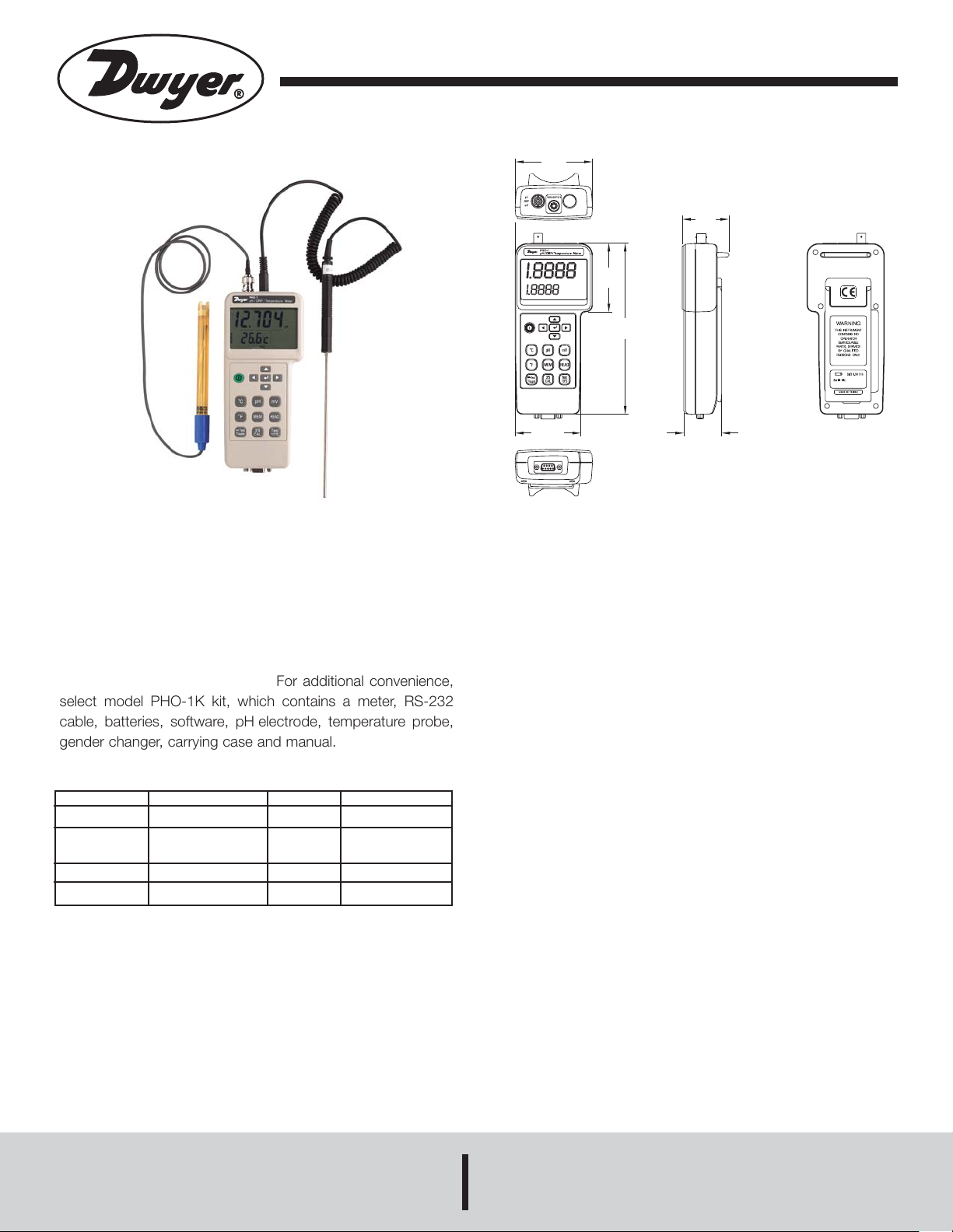
Model PHO-1 pH/ORP/Temperature Meter
Specifications - Installation and Operating Instructions
3-5/16
(84.14)
2
(50.8)
2-31/32
(74.9)
7-11/32
(186.20)
The microprocessor based pH/ORP/Temperature Meter
offers quick response and high accuracy. Simultaneously measure and display pH from 0 to 14 pH (0 to 1999 mV) and temperatures up to 200°F (100°C). Model PHO-1 meter features
manual or automatic temperature compensation, auto buffer
recognition, and data logging capabilities. The recording interval can be defined by the user. The meter accepts any pH
electrode with a BNC connector. For additional convenience,
select model PHO-1K kit, which contains a meter, RS-232
cable, batteries, software, pH electrode, temperature probe,
gender changer, carrying case and manual.
Measurement
pH
mV
Temp (°C)
Temp (°F)
Range
0 to 14 pH
0 to 600 mV
601 mV to 1999 mV
0 to 100°C
32 to 200°F
Resolution
0.001 pH
0.1 mV
0.1°C
0.1°F
Accuracy
±0.01 pH
±(0.05% + 1 digit)
±0.1%
±0.5°C
±0.9°F
2-13/16
(71.4)
1-5/8
(41.2)
CRITICAL DIMENSION
STANDARD TOLERANCES UNLESS NOTED:
ALL DECIMAL DIMENSIONS ±.005
ALL ANGLES ±1˝
SPECIFICATIONS
Input: pH electrode with BNC connector, temperature
probe.
Range: pH: 0.00 to 14.00 pH; mV: 0 to 1999 mV.
Te mperature: 32 to 200°F (0 to 100°C).
Operating Temperature: 32 to 122°F (0 to 50°C).
Compensated Temperature Limit: Manual (MTC): 32 to
200°F (0 to 100°C); Automatic (ATC): 32 to 200°F (0 to
100°C).
Operating Humidity: Max. 80% RH.
Sampling Rate: About 1.5 time/sec.
Battery LIfe: Approximately 120 hours.
Power Supply: Six “AA” batteries.
Power Current: Approximately 20 mA DC.
Data Output: RS-232 PC serial interface.
Dimension: 7.4˝ x 2.9˝ x 2˝ (187 mm x 73 mm x 53 mm).
Weight: 1 lb (.45 kg) meter only.
DWYER INSTRUMENTS, INC.
Phone: 219/879-8000 www.dwyer-inst.com
P.O. BOX 373 • MICHIGAN CITY, INDIANA 46361, U.S.A. Fax: 219/872-9057 e-mail: info@dwyer-inst.com
Page 2
Page 2
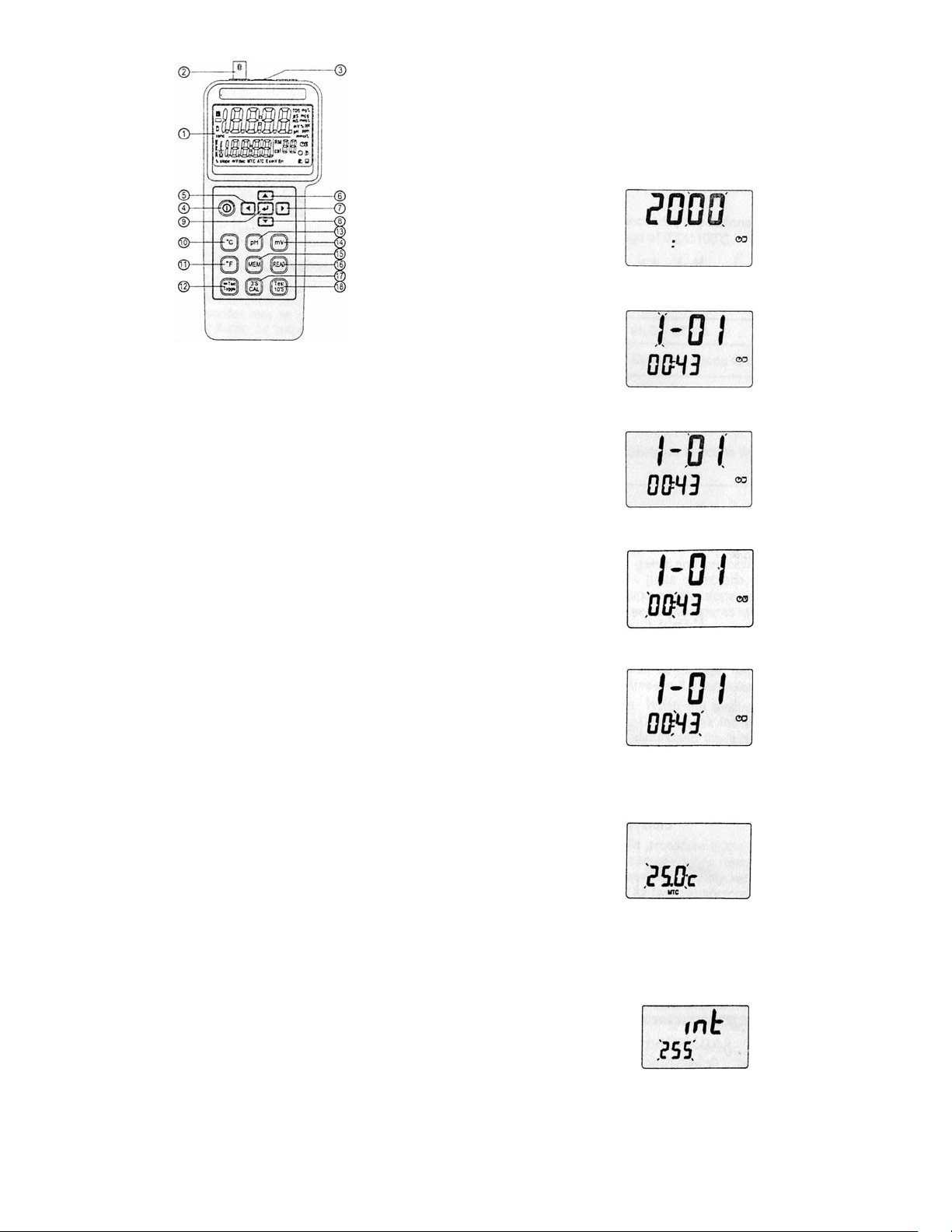
FRONT PANEL DESCRIPTION
1. LCD Display
2. Input Socket: BNC connector for pH and mV
3. Input Socket: Earphone jack for temperature probe
4. POWER Button
5. Button for moving to the desired parameters (LEFT Arrow
Key)
6. Button for increasing the value of parameters (UP Arrow
Key)
7. Button for moving to the desired parameters (RIGHT Arrow
Key)
8. Button for decreasing the value of parameters (DOWN Arrow
Key)
9. Button for entering/escaping the mode of parameter settings (ENTER Button)
10.Button for selecting temperature unit in °C (°C Temperature
Button)
11.Button for selecting temperature unit in °F (°F Temperature
Button)
12.TOGGLE Button
13.pH Button
14.mV Button
15.MEMORY Button
16.READ Button
17.CALIBRATION Button
18.TEST Button
SETUP PROCEDURE
Please follow the steps to set up the parameters for calendar
year, month, day and time (hour:minute), manual temperature
compensation (MTC), and recording time interval.
1. Press ENTER for 2 seconds until a second beep is heard.
This signals that you are entering the setup mode.
2. To change the year press the UP or DOWN arrow keys.
3. Press the RIGHT arrow key to set up for next parameter.
4. To change the month press the UP or DOWN arrow keys.
5. Press the RIGHT arrow key to set up for next parameter.
6. To change the date, press the UP or DOWN arrow keys.
7. Press the RIGHT arrow key to set up for next parameter.
8. To change the hour press the UP or DOWN arrow keys.
9. Press the RIGHT arrow key to set up for next parameter.
10.To change the minute press the UP or DOWN arrow keys.
11.Press the RIGHT arrow key to set up for the next parame-
ter.
12.To change manual temperature compensation (MTC), press
the UP or DOWN arrow keys.
pH TEMPERATURE COMPENSATION
pH Temperature Compensation ensures proper pH values by
correcting temperature variances. Compensation is accomplished manually by making adjustments in the compensation
mode or automatically by using the temperature sensing probe
in tandem with the pH electrode.
Temperature Compensation Mode:
1. Automatic temperature compensation (ATC): Plug the
temperature probe into the top jack marked temperature.
ATC will appear at bottom of the display. Immerse probe in
test solution.
2. Manual temperature compensation (MTC): Manually enter
the temperature of the test solution between 0 and 100°C.
(An ATC probe will override manual compensation.) The
preset temperature of pH Meter is 25°C. (See setup
procedure to set MTC).
13.Press the RIGHT arrow key to set up for the next parameter.
14.To change the interval time, press the UP or DOWN arrow
keys. This is the time between measurements in the
continuously recording mode.
15.To finish the settings and return to measuring mode, press
ENTER.
Page 3

CALIBRATION
pH Calibration Procedure
To ensure accuracy, calibration procedure should be done at
the initial setup of the instrument and periodically through the
life of the sensor. If the accuracy is outside the limits of the
instrument, the display will show “Err”.
1. Connect the pH electrode to the BNC socket and place the
electrode into the buffer solution (pH 7.00).
2. If using ATC, connect the temperature probe to the
temperature jack and place probe into buffer solutions
otherwise the unit will default to MTC.
3. Wait for the reading to become stable.
4. Press and hold CALIBRATION button for 3 seconds to enter
the calibration mode.
Page 3
Temperature Calibration Procedure
1. Connect the temperature probe into the earphone jack.
Place the temperature probe into a 0°C ice solution.
2. Press and hold the CALIBRATION button for 3 seconds.
3. Press the °C button.
4. Press ENTER button to complete calibration.
MEASURING PROCEDURE
pH Measurement
Calibrate the instruments and pH electrode before measuring.
1. Connect the pH electrode to the BNC socket.
2. Power on the instrument by pushing the power on/off
button.
3. Place the electrode into the solution to measure pH value.
4. After each measurement, rinse electrode with distilled water.
mV Measurement
This instrument has a built-in mV measuring function which is
capable to take ORP or other precise mV measurements. To
switch to mV measurement, press and hold mV key for one
second.
5. Press pH button (The preset value is pH 7.000 or user can
press the UP or DOWN arrow keys to select the desired pH
value).
6. Press ENTER button to offset calibration.
7. Rinse electrode and blot with lint-free tissue.
Temperature Measurement
1. Plug the temperature probe into the temperature jack (MTC
will change to ATC).
2. Place probe into the solution.
Data Hold
To freeze a reading during measurement, press the TEST TOGGLE button. An A will be displayed on the LCD to indicate that
the instrument is in hold mode. To return to measuring status,
press the TEST TOGGLE button and the A indicator will be
removed, indicating the instrument is in measuring mode.
Recording Data
The meter can perform single point data recording or continuous recording.
Individual Recording: Press the MEMORY button to record
a single data point (M1-M99).
Continuous Recording: Press and hold the memory button
for two seconds. Display will show “M” followed by the set
number. “M” will blink each time a data point is recorded.
8. For second buffer solution (pH 4.010), repeat steps 2 to 7.
Recalling Memory: To view individual points press READ
button, the LCD will show the last record. Press UP and
DOWN button to view the data that has been recorded. R1
to R99 indicates the order of readings you measured.
To view the continuous recorded data requires use of the
enclosed software.
To clear memory, turn off instrument. Press and hold the MEMORY button. Press POWER button. “CLt” will be displayed on
LCD to verify memory cleared.
Page 4

ELECTRODE PRECAUTIONS AND LIMITATIONS
1. Do not allow the electrode to dry.
2. Do not wipe the electrode tip. Blot it with a lint-free tissue.
3. Do not leave the electrode in organic solvents, strong basic
solutions, concentrated fluoride solutions or hydrofluoric
acid for extended periods of time. If measurements are
made in these solutions, readings should be taken quickly
and the electrode should be rinsed immediately with
deionized water. After rinsing the electrode, soak it in 7.0
buffer for two hours before using it again.
4. Do not use the electrodes in solutions that exceed a
temperature range of 0 to 100°C.
5. pH only.
CAUTION: To prevent permanent damage, care should be
taken to prevent liquid from entering the pH meter. Also, if
instrument will not be in service for an extended period of time,
please remove batteries.
BATTERY REPLACEMENT
1. When the LCD shows, “ ” , it indicates that the normal
+
–
battery output is less than 6.8 V and is time to replace the
battery.
2. Remove the battery cover.
3. Replace batteries with new batteries and replace back
cover.
4. Ensure the 6 AA battery cover is secured.
ELECTRODE CONDITION CHART
98.0 - 102.0%
Electrode is in good condition.
95.0 - 97.9%
Electrode needs to be cleaned.
92.0 - 94.9%
Electrode needs to be cleaned.
Electrode needs to be renewed.
MAINTENANCE
Proper use and protection of the electrode will prolong the life
of the glass membrane. If your pH electrode is exhibiting slow
response, low slope values, continuous drift, or erratic readings, follow the procedure listed below.
Cleaning the pH Bulb
1. Protein contamination: Soak the electrode bulb/tip in a 10%
solution of pepsin for 30 minutes. Rinse with deionized
water and soak the electrode in 7.0 buffer for two hours
before using.
2. Oil contamination: Wash the electrode with a 50% wateracetone solution. Do not soak the electrode in the acetone
solution or it will deteriorate the bottom seals of the plastic
electrode. Rinse with deionized water and soak the
electrode in 7.0 buffer for two hours before using.
WARRANTY
Calibration prior to use is recommended. The internals of
Model PHO-1 are not field serviceable and should be returned
if repair is needed (field repair should not be attempted and
may void warranty). Be sure to include a brief description of the
problem plus any relevant application notes. Contact customer
service to receive a return goods authorization number before
shipping. Calibration prior to use is recommended.
Recondition of the pH Bulb
Only use this procedure if the preceding maintenance and
cleaning procedures fail to restore acceptable electrode performance. Rinse electrodes immediately with deionized water and
soak in 7.0 buffer for two hours before using.
©Copyright 2005 Dwyer Instruments, Inc. Printed in U.S.A. 9/05 FR# R1-443346-00
DWYER INSTRUMENTS, INC.
Phone: 219/879-8000 www.dwyer-inst.com
P.O. BOX 373 • MICHIGAN CITY, INDIANA 46361, U.S.A. Fax: 219/872-9057 e-mail: info@dwyer-inst.com
 Loading...