

Page 1
Bulletin TE-PCHP
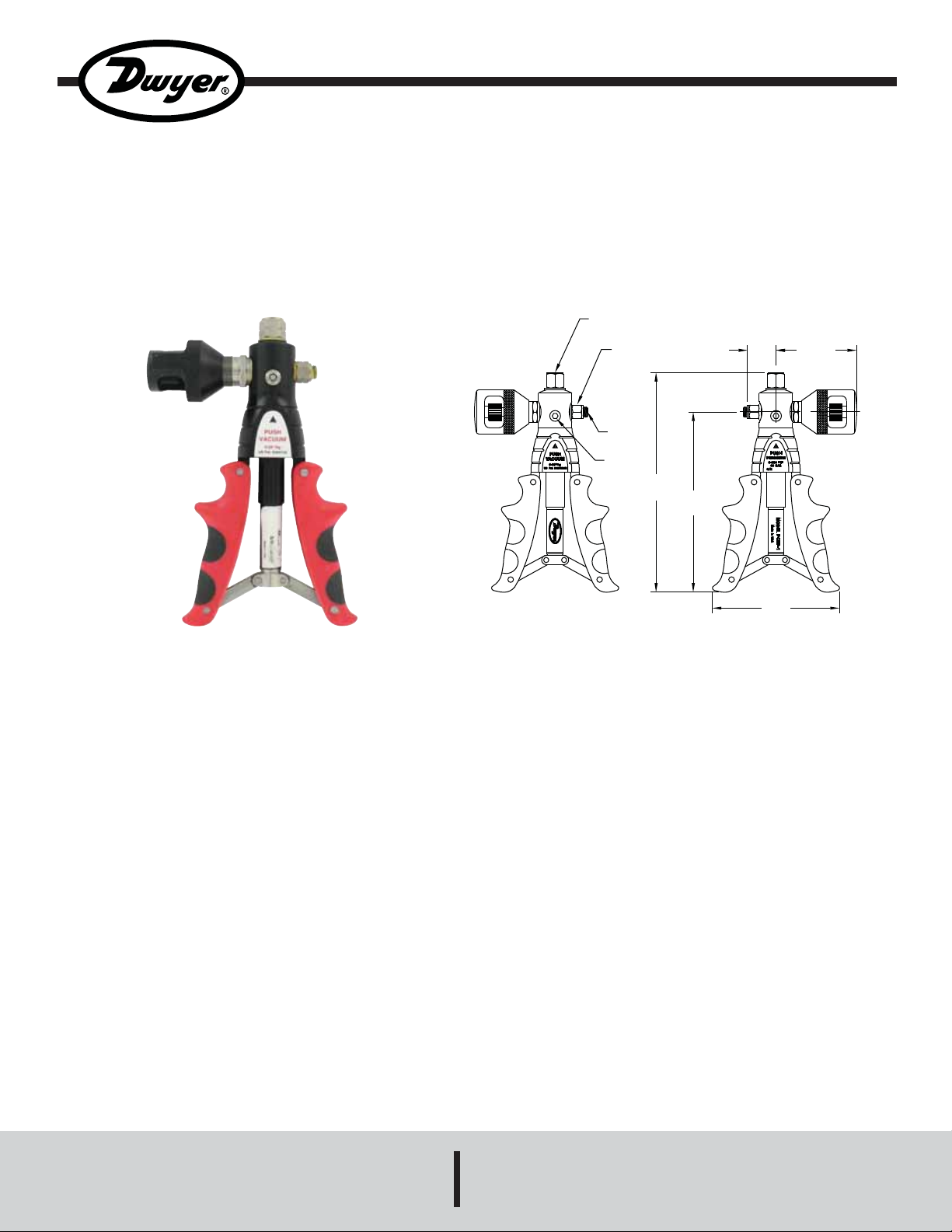
Series PCHP Pneumatic Calibration Hand Pump
Specifications - Installation and Operating Instructions
1/4 BSP WITH
1/4 NPT ADAPTER
1/8 BSP WITH
1/8 NPT ADAPTER
1/8 NPT
PLUG
SLIDE
BUTTON
8-41/64
(219.48)
(28.58)
7-3/32
(180.18)
1-1/8
3-11/64
(80.57)
The Series PCHP Pneumatic Hand Pump comfortably
sources pressure and vacuum to check calibration of gages,
switches, transmitters, and recorders. The contoured cushion handles provide extra comfort while preventing the pump
from sliding. The oversized check valve provides smooth
operation throughout the output range. The dual o-rings on
all pistons ensure zero leakage.
5
(127)
SPECIFICATIONS
Media: Air and compatible gases only.
Output Ranges: -28˝ Hg to 600 psi (-0.945 to 40 bar).
Process Connection: 1/4˝ NPT/BSP.
Gauge Connection: 1/8˝ NPT/BSP.
Materials: Stainless steel fittings, anodized aluminum
housing, plastic/rubber handles, and nitrile o-rings.
Weight: 2 lbs (0.91 kg).
DWYER INSTRUMENTS, INC.
Phone: 219/879-8000 www.dwyer-inst.com
P.O. BOX 373 • MICHIGAN CITY, INDIANA 46361, U.S.A. Fax: 219/872-9057 e-mail: info@dwyer-inst.com
Page 2
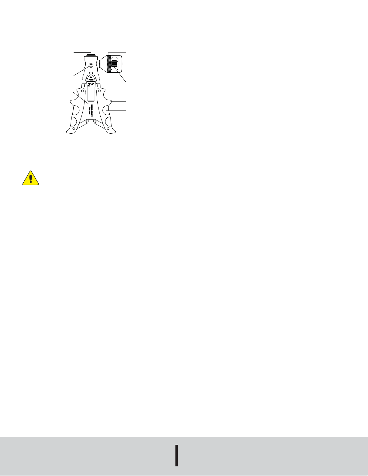
OPERATION
TOP PORT
SIDE PORT
PRESSURE/
VACUUM
SWITCH
SPRING
COVER
Fig. 1
VERNIER KNOB
VENT KNOB
KNOB GRIP
HANDLE
CUSHION
SPRING
TENSION
ADJUSTER
Volume Control
The pump is equipped with two knobs for fine adjustment
of the system pressure. The vent knob can be used to
slowly reduce the system pressure. The vent knob should
be closed prior to pressurizing the system by turning the
knob away from the pump housing. The Vernier knob can
be used to increase or decrease the system at a more
controlled rate. For fast relieve of the pressure, move the
pressure/vacuum pin to the opposite direction.
Over Pressure Protection
For a maximum pressure of 600 psi, the handles should be
3/4˝ apart at the closest point. To reduce the maximum
pressure, adjust the spring tension via the hex nut at the
bottom of the main shaft between the handles. The closer
the handles are to each other, the lower the amount of
pressure that will be able to be generated.
Insure all gauges and instruments to be calibrated are disconnected from process pr essures
before connecting the pump. The maximum
pump design pressure is 600 psig. Connection
to a pressure sources gr eater than 600 psig could
cause serious injury.
Fittings
The pump is equipped with 1/8˝ and 1/4˝ BSP ports. In
order to use NPT fittings, a NPT to BSP Parallel Thread
Adapter is required. These adapters, which are included
with the pump, have a bonded washer attached to the male
end of the adapter.
CAUTION! Do not use thread sealant paste or tape to
seal the adapters to the pump. Do not over tighten
adapters.
The pump uses a Schrader valve instead of a needle valve.
Thus, full open or closed is several turns from the end of the
travel. Over-tightening does not increase the seal.
Pressure/Vacuum Selector
The pump can be used to generate pressure or vacuum
depending on the position of the pin located in the
pressure/vacuum switch. Press the pin on the side of the
pump housing according to labels for the desired operation.
For High Pressure Operation
Prior to pressurizing, back out the V ernier knob until the ring
on the Vernier shaft is showing. Pump to pressurize. Turn
the Vernier knob towards the pump housing and the
pressure should easily be able to reach 600 psi.
MAINTENANCE
Upon final installation of the Series PCHP Pneumatic
Calibration Hand Pump, no routine maintenance is required.
A periodic check of system calibration is recommended.
The Series PCHP is not field serviceable and should be
returned if repair is needed (field repair should not be
attempted and may void warranty). Be sure to include a
brief description of the problem plus any relevant
application notes. Contact customer service to receive a
return goods authorization number before shipping.
©Copyright 2008 Dwyer Instruments, Inc. Printed in U.S.A. 6/08 FR# R6-443631-00
DWYER INSTRUMENTS, INC.
Phone: 219/879-8000 www.dwyer-inst.com
P.O. BOX 373 • MICHIGAN CITY, INDIANA 46361, U.S.A. Fax: 219/872-9057 e-mail: info@dwyer-inst.com
 Loading...