

Page 1
Important Points!
Product must be maintained and installed in strict accordance
with the National Electrical Code and Dwyer product catalog
and instruction bulletin. Failure to observe this warning could
result in serious injuries or damages.
In-Line Flow Switches
P2 Series
For hazardous area applications involving such things as (but
not limited to) ignitable mixtures, combustible dust and
flammable materials, use an appropriate explosion-proof
enclosure or intrinsically safe interface device.
The pressure and temperature limitations shown on the
individual catalog pages and drawings for the specified flow
switches must not be exceeded. These pressures and
temperatures take into consideration possible system surge
pressures/temperatures and their frequencies.
Selection of materials for compatibility with the media is critical
to the life and operation of Dwyer products. Take care in the
proper selection of materials of construction, particularly wetted
materials.
Life expectancy of switch contacts varies with applications.
Contact Dwyer if life cycle testing is required.
Ambient temperature changes do affect switch set points,
since the specific gravity of a liquid can vary with temperature.
Dwyer Products have been designed to resist shock and
vibration; however, shock and vibration should be minimized.
Filter liquid media containing particulate and/or debris to
ensure the proper operation of our products.
Electrical entries and mounting points in an enclosed tank
may require liquid/vapor sealing.
P2 Model Flow Switches operate reliably in any mounted attitude for which they
are calibrated. Other attitudes will slightly alter actuation settings. Unless
otherwise specified, units are calibrated in the vertical inlet port down position.
Installation . . .
- Warning The P2 is a plastic, taper-threaded instrument.
Over-tightening will result in port breakage!
All plastic NPT threads should be installed using a suitable thread sealant.
(Teflon tape or Permatex "No More Leaks"). Sealant must be kept out of unit
during installation. Improper installation to a process can result in cracking.
Install fittings or adapters onto flow switch using strap wrenches. One to two
turns past hand-tight is adequate.
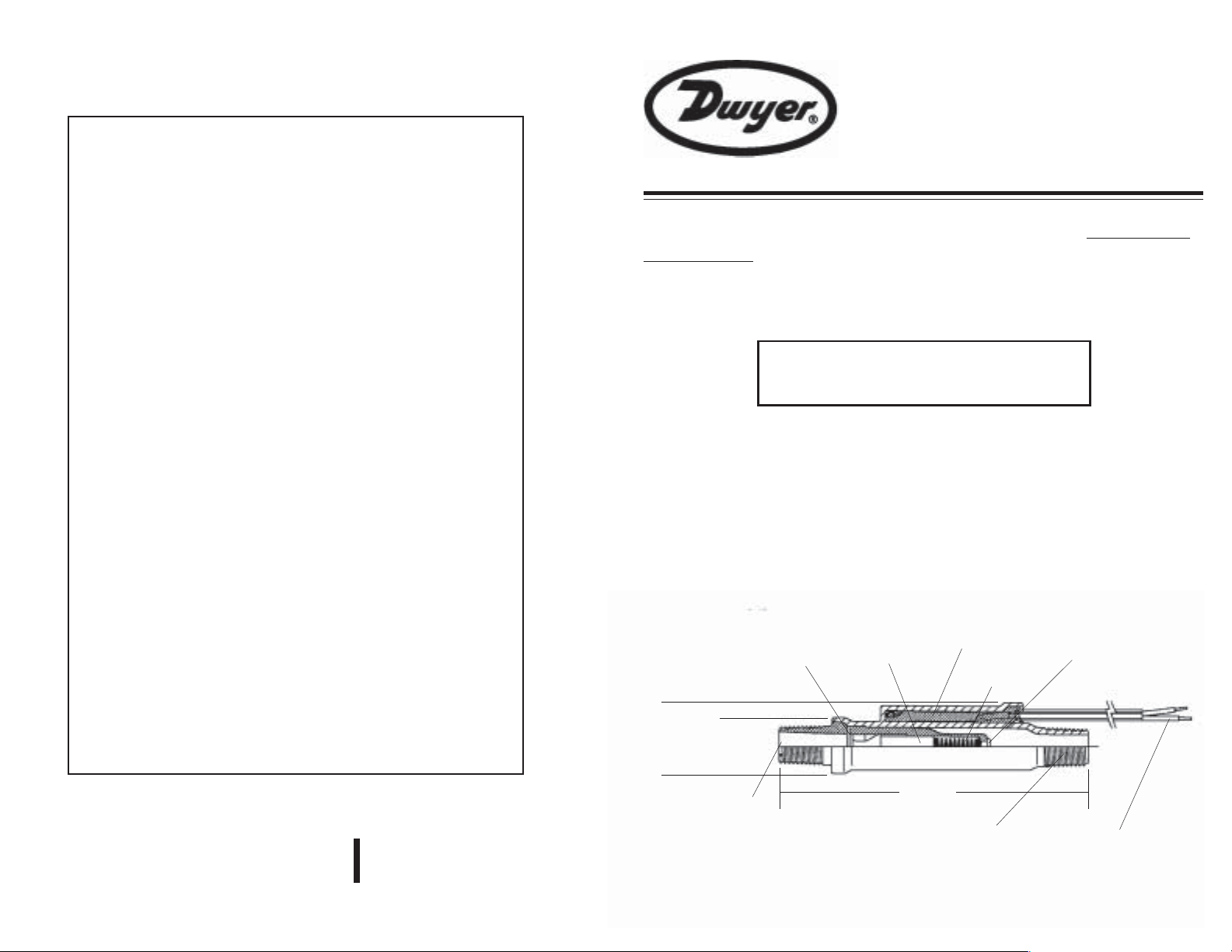
Dimensional Data . . .
Retaining
Wire
Piston
Assembly
Switch
Assembly
Spring
End Plug
Air (Gas) Flow Units
Only
Dwyer Products must not be field-repaired.
Physical damage sustained by the product may render it
unserviceable.
DWYER INSTRUMENTS,INC.
P .O.BOX 373 MICHIGAN CITY, INDIANA 46361, U.S.A.
Phone: 219/879-8000
Fax: 219/872-9057
Lit-By Fax: 888/891-4963
www.dwyer-inst.com
e-mail: info@dwyer-inst.com
1"
(25.4 mm)
.78" dia.
(19.7 mm)
Inlet
4.10"
(104.3 mm)
Mechanical
Port Thread
Typ. 1/4" NPT
or R 1/4"
Outlet
- #22 AWG PVC Lead Wire
(1/4" NPT)
- Conductor PVC Cable
(R 1/4")
Page 2
Specifications . . .
Wetted Materials (FDA or NSF-Compliant)
Housing and Barbs
Piston
Spring and Stop Pin
Pressure Rating
Operating Temperature
Required Filtration
Switch, See "Switch Ratings"
Electrical Termination
Noryl
Noryl
316 Stainless Steel
150 PSI @ 70oF
50 PSI @ 212oF
212oF (100°C), Max.
50 Micron or Better
SPST, N.O. Pilot Duty 20 VA,
120-240 VAC or VDC
No. 22 AWG, 18" L., PVC Lead Wires
(1/4"NPT )
No. 22 AWG, 18" L., PVC
2-Conductor Cable (R 1/4")
®
®
and Epoxy
P2 Flow Switches Can Be
Mounted In Various Attitudes. . .
Note: Flow settings are based on a
vertical position (inlet port down), using
water at +70°F on increasing flow. Some
variation in set point actuation will occur in
other mounting orientations.
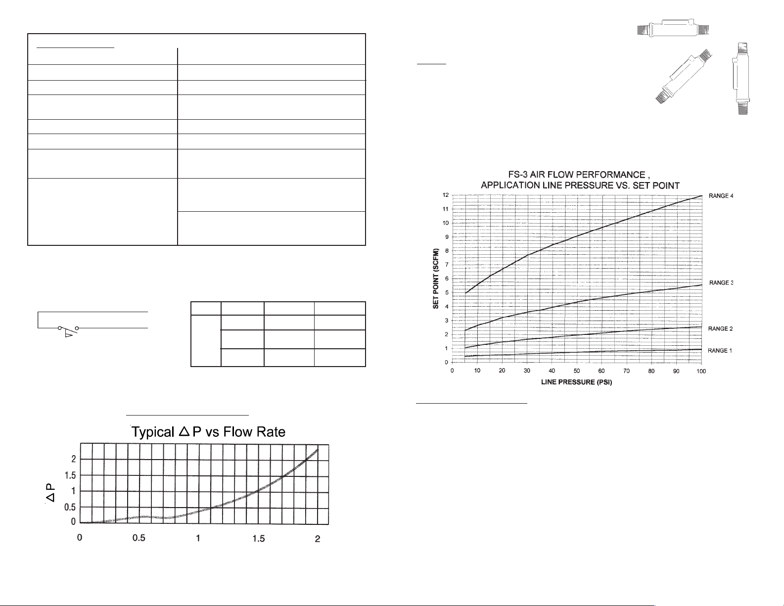
There are four standard air flow models of the FS-3. Set point will vary
with line pressure, as shown in the graph below.
Wiring Diagram . . .
Normally Open
Pressure Drop Data
(PSI)
Switch Ratings
Max. Resistive Load
VA
20
Flow Rate (GPM, Water)
Volts
0-30
120
240
Amps AC Amps DC
.4
.17
.08
.3
.13
.06
MAINTENANCE/REPAIR
Regular maintenance of the total system is recommended to assure sustained
optimum performance. These devices are not field repairable and should be
returned to the factory if recalibration or other service is required. After first obtaining a Returned Goods Authorization (RGA) number, send the unit freight prepaid
to the following. Please include a clear description of the problem plus any application information available.
Dwyer Instruments, Inc.
Attn: Repair Department
102 Highway 212
Michigan City, IN 46360
 Loading...