

Page 1
Instruction Manual
INM7700
MTL7700 Series
Shunt-diode safety barriers
Page 2

ii
INM7700-6 Jan 2010
Page 3

1 OVERVIEW . . . . . . . . . . . . . . . . . . . . . . . . . . . . . . . . . . . . . . . . . . . . . . . . . . . . . . . . . . . . . . 1
2 DESCRIPTION . . . . . . . . . . . . . . . . . . . . . . . . . . . . . . . . . . . . . . . . . . . . . . . . . . . . . . . . . . . . 1
2.1 Introduction . . . . . . . . . . . . . . . . . . . . . . . . . . . . . . . . . . . . . . . . . . . . . . . . . . . . . . . . . . . . . . . . . . . . . . . . . . . . 1
2.2 MTL7700 Series – barrier ranges . . . . . . . . . . . . . . . . . . . . . . . . . . . . . . . . . . . . . . . . . . . . . . . . . . . . . . . . . . . . . 1
2.3 MTL7700 Series – accessories . . . . . . . . . . . . . . . . . . . . . . . . . . . . . . . . . . . . . . . . . . . . . . . . . . . . . . . . . . . . . . . 2
3 SAFETY CONSIDERATIONS . . . . . . . . . . . . . . . . . . . . . . . . . . . . . . . . . . . . . . . . . . . . . . . . . . . 3
3.1 General requirements . . . . . . . . . . . . . . . . . . . . . . . . . . . . . . . . . . . . . . . . . . . . . . . . . . . . . . . . . . . . . . . . . . . . . 3
3.2 Safety checks . . . . . . . . . . . . . . . . . . . . . . . . . . . . . . . . . . . . . . . . . . . . . . . . . . . . . . . . . . . . . . . . . . . . . . . . . . 3
4 INSTALLATION . . . . . . . . . . . . . . . . . . . . . . . . . . . . . . . . . . . . . . . . . . . . . . . . . . . . . . . . . . . 3
4.1 General . . . . . . . . . . . . . . . . . . . . . . . . . . . . . . . . . . . . . . . . . . . . . . . . . . . . . . . . . . . . . . . . . . . . . . . . . . . . . . 3
4.2 Mounting/removing barriers . . . . . . . . . . . . . . . . . . . . . . . . . . . . . . . . . . . . . . . . . . . . . . . . . . . . . . . . . . . . . . . . 3
4.3 Installing accessories . . . . . . . . . . . . . . . . . . . . . . . . . . . . . . . . . . . . . . . . . . . . . . . . . . . . . . . . . . . . . . . . . . . . . 3
5 WIRING CONNECTIONS . . . . . . . . . . . . . . . . . . . . . . . . . . . . . . . . . . . . . . . . . . . . . . . . . . . . . 7
5.1 General . . . . . . . . . . . . . . . . . . . . . . . . . . . . . . . . . . . . . . . . . . . . . . . . . . . . . . . . . . . . . . . . . . . . . . . . . . . . . . 7
5.2 Barrier connections . . . . . . . . . . . . . . . . . . . . . . . . . . . . . . . . . . . . . . . . . . . . . . . . . . . . . . . . . . . . . . . . . . . . . . . 7
5.3 Connections to plant earth . . . . . . . . . . . . . . . . . . . . . . . . . . . . . . . . . . . . . . . . . . . . . . . . . . . . . . . . . . . . . . . . . . 7
5.4 Connections to dummy barriers . . . . . . . . . . . . . . . . . . . . . . . . . . . . . . . . . . . . . . . . . . . . . . . . . . . . . . . . . . . . . . 9
6 MAINTENANCE . . . . . . . . . . . . . . . . . . . . . . . . . . . . . . . . . . . . . . . . . . . . . . . . . . . . . . . . . . . 9
6.1 General . . . . . . . . . . . . . . . . . . . . . . . . . . . . . . . . . . . . . . . . . . . . . . . . . . . . . . . . . . . . . . . . . . . . . . . . . . . . . . 9
6.2 Routine inspection . . . . . . . . . . . . . . . . . . . . . . . . . . . . . . . . . . . . . . . . . . . . . . . . . . . . . . . . . . . . . . . . . . . . . . . 9
7 FAULT-FINDING . . . . . . . . . . . . . . . . . . . . . . . . . . . . . . . . . . . . . . . . . . . . . . . . . . . . . . . . . . 10
7.1 Introduction . . . . . . . . . . . . . . . . . . . . . . . . . . . . . . . . . . . . . . . . . . . . . . . . . . . . . . . . . . . . . . . . . . . . . . . . . . . 10
7.2 Power supply check . . . . . . . . . . . . . . . . . . . . . . . . . . . . . . . . . . . . . . . . . . . . . . . . . . . . . . . . . . . . . . . . . . . . . 11
7.3 Barrier resistance test . . . . . . . . . . . . . . . . . . . . . . . . . . . . . . . . . . . . . . . . . . . . . . . . . . . . . . . . . . . . . . . . . . . . 11
8 EQUIPMENT AND BARRIER TESTS . . . . . . . . . . . . . . . . . . . . . . . . . . . . . . . . . . . . . . . . . . . . . 11
8.1 Thermocouple and RTD tests . . . . . . . . . . . . . . . . . . . . . . . . . . . . . . . . . . . . . . . . . . . . . . . . . . . . . . . . . . . . . . . . 11
8.2 Barrier tests . . . . . . . . . . . . . . . . . . . . . . . . . . . . . . . . . . . . . . . . . . . . . . . . . . . . . . . . . . . . . . . . . . . . . . . . . . . 11
8.3 Tests for Active Barriers . . . . . . . . . . . . . . . . . . . . . . . . . . . . . . . . . . . . . . . . . . . . . . . . . . . . . . . . . . . . . . . . . . . 12
8.4 Test tables for passive barriers . . . . . . . . . . . . . . . . . . . . . . . . . . . . . . . . . . . . . . . . . . . . . . . . . . . . . . . . . . . . . . 14
APPENDIX A: TYPICAL WIRING CONNECTIONS FOR SPECIFIC APPLICATIONS. . . . . . . . . . . . . . . . . . . 17
CONTENTS PAGE
© 2010 MTL Instruments Group plc. All rights reserved.
INM7700-6 Jan 2010
iii
Page 4

INM7700-6 Jan 2010
iv
Page 5
1
INM7700-6 Jan 2010
MTL7700 Series
Shunt-diode safety barriers
INM7700-6
Jan 2010
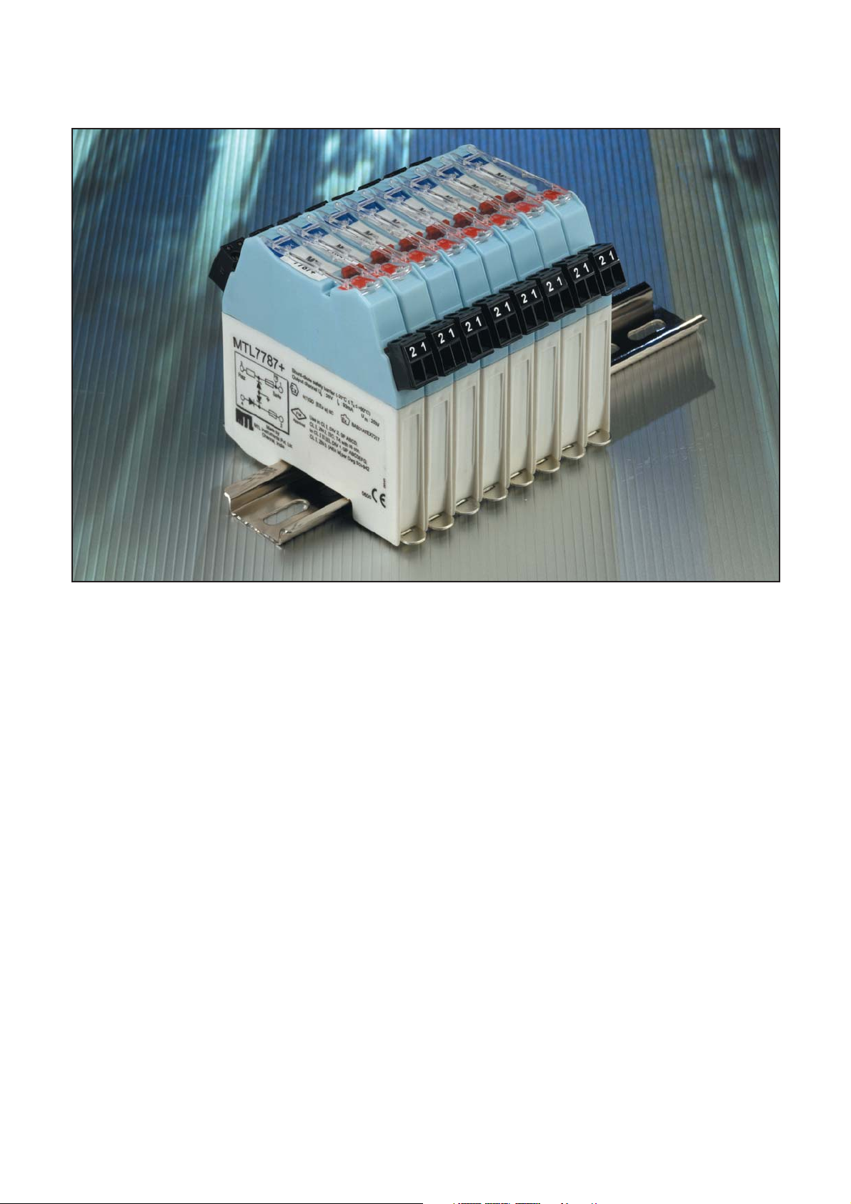
Figure 1: MTL7700 Series shunt-diode safety barriers
1 OVERVIEW
This instruction manual contains all information needed to install,
maintain, fault-find and test MTL7700 Series shunt-diode safety
barriers.
Section 3 includes a checklist of essential safety factors that must
be considered when using MTL7700 Series barriers as intrinsically
safe (IS) interfaces between safe and hazardous areas.
Read section
3 before beginning installation
. Users within the European
Community should also refer to the supplied MTL publication:
INA7700 MTL7700 Series
Instructions for Safe Use
It is assumed that all necessary system design, specification and
engineering factors have been taken into account BEFORE installation
work begins. To assist pre-planning, the following MTL publications
covering the theory, design, application, specifications and
certification of shunt-diode safety barriers are available:
AN9003 Application Note:
A user’s guide to
intrinsic safety
AN9007 Application Note:
A user’s guide to
MTL700 Series shunt-diode safety
barriers
MTL IS catalogue The MTL IS catalogue includes detailed
specifications of all MTL7700 Series
barriers and accessories
IS certificates Copies of Baseefa, FM and CSA IS
apparatus and system certificates for
MTL7700 Series barriers
If not supplied with the product, these publications are available
either from the company website (
www.mtl-inst.com
) or on request
from your local MTL office.
2 DESCRIPTION
2.1 Introduction
MTL7700 Series ‘fourth-generation’ intrinsically safe shunt-diode
safety barriers are innovative successors to the MTL700 Series.
MTL7700 Series barriers are 1-, 2- or 3-channel devices that use
intrinsically safe explosion-protection techniques to pass electrical
signals between safe and hazardous areas, whilst limiting transferred
energy to a level that cannot ignite flammable atmospheres.
Connected in series with wiring entering any hazardous area on
process plant, MTL7700 Series barriers prevent explosions in all
normally occurring explosive atmospheres – including mixtures of air
with flammable gases, vapours, dusts and fibres – if a fault or faults
develop in the safe area.
2.2 MTL7700 Series – barrier ranges
The range is based on a choice of models which, between them,
cover virtually all applications – including the protection of
installations incorporating uncertified devices known as ‘simple
apparatus’ (eg, switches, thermocouples, resistive sensors, photocells
and LEDs) or separately certified ‘energy-storing’ or ‘voltageproducing apparatus’ (eg, ac sensors, proximity detectors,
transmitters and current-to pneumatic (I/P) converters. Being
intrinsically safe, shunt-diode barriers enable maintenance work or
calibration to be carried out ‘live’ without additional precautions. To
simplify selection, several ‘key’ barriers (see table 1) are highlighted
as meeting the majority of process control requirements.
Page 6
2
INM7700-6 Jan 2010
2.3 MTL7700 Series – accessories
MTL7700 Series barriers mount directly onto DIN-rail. A
comprehensive selection of mounting, tagging, power and earthing
accessories is available. Installation details are given in section 4.3.
Essential accessories
The following are usually considered essential for mounting and
earthing MTL7700 Series barriers:
DIN-rail (eg, THR2 or THR7000)
Insulating spacers (eg, ISP7000)
Earth terminal (eg, ETL7000)
The tagging systems for individual modules and columns of barriers
are described here. They are shown below under Tagging
accessories for columns of barriers.
Mounting accessories (figure 2)
THR2 Standard DIN-rail, 35 x 7.5mm, (in 1m lengths)
THR7000 Nickel-plated DIN-rail, 35 x 7.5mm, for use in
potentially corrosive atmospheres (in 1m lengths)
ISP7000 Insulating spacer: attaches to the base of a DIN-
rail to isolate the IS earth from a structural earth
Tagging accessories for individual barriers (figure 2)
TH7700 Tag holder for mounting on the top of an
individual barrier
Tagging accessories for columns of barriers (figure 2)
TAG57 Tagging strips for mounting over a column of
barriers, for marking barrier locations. Supplied
(with labels) in 1m lengths for cutting to size.
TGL7700 Spare labels for use with TAG57 tagging strips:
0.5m strips, supplied in sets of 10.
IMB57 Tagging strip supports. Two needed for each
tagging strip. It can also be used as centre
support by breaking off the top end tab.
Power accessories (figure 3)
BPL7700 Power link for feeding 24V dc to a maximum of
40 barriers in a single column from an MTL7798
power feed module or MTL7799 Dummy
module.
Earthing accessories (figure 3)
ETL7000 Earth terminal providing connections for
routeing the IS earth from the DIN-rail to an
appropriate plant earth. Two recommended for
each length of DIN-rail.
TAG57
TGL7700
ERB57O
IMB57
ETL7000
ISP7000
TH7700
Figure 2: MTL7700 Series mounting and tagging accessories
Table 1: MTL7700 Series Key barriers
Type Application Key barriers
MTL
Analogue Resistance temperature detectors 7755ac
input Thermocouples, ac sensors 7756ac
(low-level) 7760ac
Analogue Controller outputs, one line earthed 7728+
output Controller outputs, neither line earthed 7787+
dc power supply
26V 20-35V
Analogue Transmitters, 2-wire, 4–20mA 7787+ 7706
input
(high-level)
Digital Switches 7787+ 7707+
(on/off) 7741-44
input
Digital Solenoids, alarms, LEDs 7728+ 7707+
(on/off)
output
Page 7
3
INM7700-6 Jan 2010
ERB57O
IMB57
ETL7000
ERL7
ETM7
ISP7000
THR2/THR7000
Figure 3: MTL7700 Series earthing accessories
Note: Module earth terminals may be used for cable
screen earth connections. See Figure 17
ERB57S Nickel-plated straight earth-rail bracket,
supplied with two push fasteners, one 14mm
earth-rail clamp and one 9mm earth clamp <
16mm2.
ERB57O Nickel-plated offset earth-rail bracket, supplied
with two push fasteners, one 14mm earth-rail
clamp and one 9mm earth clamp < 16mm
2
.
ERL7 Nickel-plated 3 x 10mm earth rail supplied in
1m lengths. Provides earthing facilities for cable
screens and 0V earth returns, additional to those
provided on the module earth foot.
ETM7 Earth terminal (5mm wide) for attachment to an
ERL7 earth rail, for terminating cable screens
and spare cable cores.
3 SAFETY CONSIDERATIONS
3.1 General requirements
All installers of shunt-diode barriers should be familiar with the
installation instructions provided by nationally accepted codes of
practice, eg, BS EN 60079-14 for the UK, or a recommended
practice, eg, ANSI/ISA-RP 12.6 for the USA.
Users within the European Community should also refer to the
supplied MTL publication:
INA7700 MTL7700 Series
Instructions for Safe Use
3.2 Safety checks
Table 2 itemises the essential checks that should be carried out to
ensure the safety of a barrier installation. Use the checklist to prevent
important safety considerations being overlooked when installing,
commissioning, modifying or servicing an installation of MTL7700
Series barriers. Check the list both before and after a barrier system
has been installed, the final check being made by someone other
than the person(s) who carried out the installation work. Each item in
the list is cross-referenced to the appropriate section of the manual.
For Factory Mutual (FM) based installations see also Appendix B
for FM certification information.
4 INSTALLATION
4.1 General
MTL7700 Series barriers clamp directly onto standard T-section DINrail (DIN EN 50 022). The simple mounting procedure for barriers is
described in section 4.2 and for accessories in section 4.3.
4.1.1 DIN-rail length
BEFORE mounting the barriers, make sure the rail length is sufficient
for the proposed number of barriers and for other mounting
accessories. As a guide, on a given length of DIN-rail, allow space
(length) for:
a) Barrier packing pitch: 12.6mm
b) ETL7000 earth terminals: 10mm each (minimum
of two)
c) IMB57 tagging strip support 16.0mm (minimum of
(if specified) two)
d) ISP7000 insulating spacer 14.7mm (minimum of
(if specified) two)*
e) ERB57S or O earth-rail 8 mm (minimum of two)
mounting bracket
(if specified)
* See Note in section 4.3.2
Make sure that there is sufficient clearance between the DIN-rail and
any possible obstruction (eg, other columns of barriers) to remove
barriers and install accessories such as ERB57S/O earth rails.
Provide sufficient height for IMB57 tagging strip supports and
ISP7000 insulating spacers when fitted.
As a guide, refer to figure 4 (dimensions of an individual barrier) and
figure 5 (clearances needed for accessories).
4.2 Mounting/removing barriers
MTL7700 Series barriers clamp directly onto T-section DIN-rail,
earthing the barrier through the rail.
a) Hook the hazardous-area end of the mounting/earthing clamp
over the hazardous-area flange of the DIN-rail (figure 6).
b) Push the safe-area end of the barrier firmly down by hand until
it clicks into place.
c) Check that the barrier is securely clamped into place (see notes
below).
d) To remove a barrier (figure 7), use the tip of a screwdriver (with
a blade width of 4 to 5mm, minimum shaft length 60mm) to ease
the metal clip at the base on the safe-area end outwards until the
barrier is freed and can be removed easily by unhooking the
hazardous-area end.
Notes
1: Make sure the barrier is properly clamped onto the rail to ensure
the essential earth connection. In a row of barriers, one end of an
improperly mounted barrier will stick up slightly.
2: Once an MTL7700 Series barrier is fitted, its mounting/earthing
foot grips the DIN-rail strongly in order to maintain positional stability
and create a high-integrity earth bond. The unit should not be forced
along the rail. If it is necessary to reposition a barrier, detach it from
the DIN-rail and re-attach it in the correct location. Where minor
repositioning is needed, relieve the pressure on the spring of the
mounting foot with a screwdriver and ease the unit into place.
4.3 Installing accessories
See section 2.3, figure 2 and figure 3 for brief details of the
accessories available for use with MTL7700 Series barriers. More
information and installation details (where relevant) for the various
accessories are detailed in the following sections:
Page 8
4
INM7700-6 Jan 2010
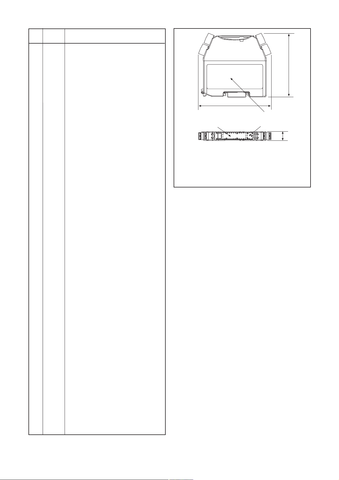
90
Hazardousarea
terminals
Safe-area
terminals
12.6
105
Installation and approval side label
Product top label
Colour-coded top label
Top label background colour codes
Red = positive barrier
Black = negative barrier
Grey = ac barrier
White = dummy barrier
Orange = power feed module
Figure 4: Dimensions (mm) of an MTL7700 Series barrier
Mounting accessories Section 4.3.1 to 4.3.
Earthing accessories Section 4.3.3, 4.3.4
Tagging accessories Section 4.3.5, 4.3.6
Power links Section 4.3.7, 4.3.8
4.3.1 DIN-rail (THR2 and THR7000)
MTL can supply both standard (THR2) and plated (THR7000) lowprofile T-section DIN-rail. Although standard DIN-rail maintains a
high-integrity earth in normal conditions, for aggressive environments
MTL provides THR7000 nickel-plated DIN-rail. Both types are
supplied in 1m lengths for cutting to size as necessary. Although there
is no strict requirement for the DIN-rail to be isolated from earthed
surfaces, it is advisable, in order to minimise the possibility of the
earth circuit being invaded by fault currents which might interact
adversely with other systems. ISP7000 insulating spacers are a
convenient method of insulating the DIN-rail. It is much easier to
install insulating spacers during the initial build, than to discover later
that an equipped and running installation must be modified.
4.3.2 Insulating spacers (ISP7000)
When used, ISP7000 insulating spacers are attached to each end of
the DIN-rail and at intervals depending upon the length of the rail. It
is recommended that spacers be mounted at 300mm intervals on lowprofile (7.5mm) DIN-rail and at 500mm intervals on high-profile
(15mm) rails – see figure 8. The spacers are provided with suitable
screws for attaching to both the DIN-rail and the mounting surface,
which will need to be suitably drilled and tapped for the purpose.
Install each spacer as follows (figure 9):
a) On the mounting surface, drill and tap two holes for M4 screws.
b) Attach the spacer to the surface with the two M4 x 16 screws
provided.
c) Drill an M6 clearance hole (6.5mm) in the centre of the base of
the DIN-rail (if not already suitably slotted)
d) Attach the DIN-rail to the spacer with the M6 x 16 screw
provided.
Table 2: Safety checklist
Item Refer to
no. section: Action
1 3.1 Before beginning installation, check that the
safety documentation confirms that the
proposed system is fully certified (if applicable)
and complies with the recommendations
contained in the relevant sections of IEC
60079-14 for the gas group, temperature
classification and area classification required.
2 4.1/6.2 Make sure the barriers are of the correct type
and polarity as specified in the safety
documentation.
3 4.1 Make sure all barriers are mounted the right
way round and are properly attached so that
the essential earth contact is made securely in
accordance with the safety documentation and
in compliance with the recommendations of IEC
60079-14.
4 5.3/6.2 Measure the resistance between the barrier
earth DIN-rail and the main power system earth
and make sure it does not exceed the maximum
permitted resistance specified in the safety
documentation.
5 4.1/6.2 Inspect carefully all cables connected between
the barriers and the hazardous-area equipment,
making sure the cables are the type specified
by the safety documentation and that they are
connected to the correct terminals.
6 5/6.2 Make sure all hazardous-area cables are well
secured and are segregated from all other
cables.
7 5 Make sure the permitted cable parameters for
hazardous-area circuits are not exceeded (see
relevant certificate or INA7700).
8 5 Make sure all hazardous-area apparatus and
cables are either earth-free or correctly bonded
with an equipotential conductor.
9 5.3/6.2 Make sure all hazardous-area cables and cable
screens are terminated correctly, the latter
preferably via earth foot on the hazardous side
of each barrier or via ERL7.
10 5.4 Make sure all unused hazardous-area cables
are terminated by a dummy barrier (MTL7799),
earth rail (ERL7) or otherwise safely connected
to earth.
11 Make sure all hazardous-area energy-storing
devices are independently and appropriately
certified.
12 4.1/ Inspect all tagging or identification labels and
4.3.5/ make sure they relate to the correct barrier
4.3.6 types, polarities and circuit loop numbers.
13 5/6.2 Inspect carefully all cables connected to the
safe-area equipment and make sure they are
connected to the safe-area terminals of the
barriers.
14 5.3 Make sure that no safe-area equipment is
supplied from (or includes) a source of potential
with respect to earth that exceeds 250V rms or
250V dc under normal or fault conditions unless
specifically permitted by the safety
documentation.
Note: One phase of a 3-phase supply of up to
440V is permitted as its value is equivalent to
250V rms.
15 Make sure all barriers are protected adequately
against moisture, dust, dirt, vibration, excessive
temperatures, physical damage and
unauthorised modifications.
Page 9

5
INM7700-6 Jan 2010
TAG57
TGL7700
ERB57O
IMB57
ETL7000
ISP7000
110mm
110mm
170mm
Figure 5: Clearance for accessories
Note: For high profile (15mm) DIN rail, add 7.5mm to vertical dimension
1
2
3
1
2
Figure 6: Clamping an MTL7700 Series barrier on to a DIN-rail
Figure 7: Removing an MTL7700 Series barrier from a DIN-rail
250mm
Low-profile rail (7.5mm)
High-profile rail (15mm)
250mm
500mm
Figure 8: Maximum DIN-rail spans between ISP7000 spacers
4.3.3 DIN-rail earth terminal (ETL7000)
See figure 10. For those applications (the majority) in which the IS
earth is NOT routed through the mounting surface, connections for
routing the IS earth from the DIN-rail to an appropriate plant earth
are made through earth terminals (ETL7000) clamped onto the DINrail. Two terminals are recommended, one at either end of a column
of barriers, to provide redundancy and to simplify earth testing
procedures.
WARNING: Apart from rare occasions when the mounting
surface carries the IS earth, the ONLY method of providing
the IS earth connection from any one column of MTL7700
Series barriers is from ETL7000 earth terminals. Never make
the plant IS earth connection to the earth screen on any
individual barrier: this is MANDATORY. See also section 5.3.
ETL7000 terminals are attached to the rail as follows. Ensure the
same security of the earth connection to the rail as for the barriers
themselves (see section 4.2):
a) Hook the fixed end-clamp of the terminal over one flange of the
DIN-rail.
b) Press the body of the terminal downwards until the pivoting end-
clamp engages the other flange of the DIN-rail.
c) Clamp the terminal firmly into place by tightening the centre
screw.
d) Important: wire up the earth terminal as given in section 5.3.2.
Page 10

6
INM7700-6 Jan 2010
High - profile
DIN rail
OR
Low - profile
DIN rail
2 off M4 x 16
M6 X 16
50mm
62mm
14.6mm
20mm
Figure 9: Mounting ISP7000 insulating spacers
ETL7000
earth terminal
Clamping
screw
Earth terminal
screws
Figure 10: Mounting an ETL7000 DIN-rail earth terminal
TH7700
LABEL
Figure 11: Installing a TH7700 barrier tag holder
4.3.4 Earth rail assembly (ERL7/ETM7/ERB57S/O)
A screw terminals on each barrier is available for terminating cable
screens and 0V returns. An alternative is provided by an earth rail
assembly (figure 12). This consists of two IMB57’s, ERB57S or O,
mounting blocks (one for each end of a column of barriers), a length
of ERL7 earth rail (supplied in 1m lengths for cutting to size), and
ETM7 terminals for connecting cable screens or 0V returns to the rail.
Install the earth rail assembly as follows:
a) Hook the loose end-clamps of the IMB57 mounting blocks over
the flanges of the DIN-rail at each end of the row of barriers.
b) Making sure the blocks are flush with the end barriers or tagging
strip supports, clamp them firmly into place by tightening the
screws at the base of the blocks and fit 2 off ERB57O or S into
supports.
c) Slide the number of ETM7 terminals required for connections
onto the length of ERL7 rail needed for the assembly.
d) Important: wire up the earth rail assembly as given in section
5.3.3.
4.3.5 Barrier identifiers (TH7700)
TH7700 tag holders (figure 11) are clipped onto the tops ofindividual
barriers to provide transparent holders for identification labels
a) Slide the required label in between the top and lower parts of
the TH7700
b) Push the tag holder downwards until it clips into place.
c) To unclip a tag holder, lever up the far end above terminals.
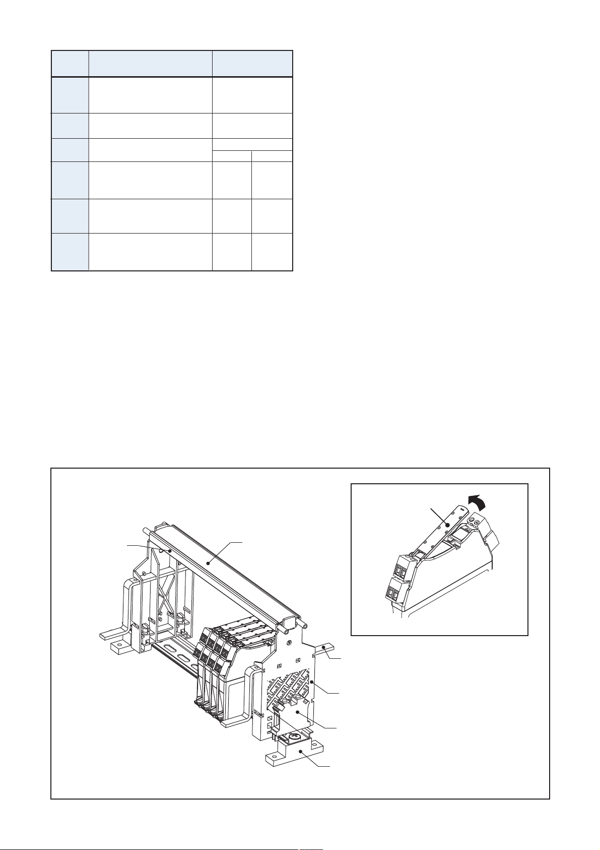
4.3.6 Tagging strip assemblies(IMB57)
The tagging strip assembly (figure 12) identifies the location of
individual barriers, ensuring that they are replaced correctly after
removal for maintenance or testing. Once installed, the tagging strip
pivots upwards to provide access to, and allow removal of, individual
barriers.
Each assembly uses two tagging strip supports (IMB57), a tagging
strip (TAG57) and tag labels (TGL7700).
The assembly installation procedure is:
a)IMB57 tagging strip support. Making sure that the vertical
slots are on the hazardous-area side, hook the loose end-clamps
of each IMB57 tagging strip support over the flanges of the DINrail at each end of the group of barriers.
b) Make sure that the tagging strip support is flush with the end
barrier in the row.
IMB57 tagging strip support. Clamp firmly in place by
tightening the two screws located at the foot of each support.
c) Remove any clic rivets from the tagging strip and slide out the
label.
d) Measure the distance between the top inside faces of the two
tagging strip supports.
e) Cut the tagging strip and label to this length with a hacksaw.
f) Annotate the tagging strip label as required and slide it back
into the tagging strip. Divisions on label strips are 12.6mm
wide, the pitch of individual barriers.
g) Clip the tagging strip onto the lugs on top of the tagging strip
supports.
4.3.7 Power bus (BPL7700)
For details on using and installing a power bus, see section 5.2.3.
Note: Early versions of TH7700 are hinged on two small locating
pins. Later versions are hinged by locating the clips at the hinged end
into the rectangular appartures on the barrier body. The later design
can be retrofitted on early modules by removing the hinge pins with
a knife.
TGL7700
ERB57O
TAG57
ERL7
ETM7
14mm earth-rail
clamp
THR2/THR7000
ERB57S
in lower position
ISP7000
ETL7000
10mm earth
clamp
IMB57
Snap off extension
when using IMB57
as a central support
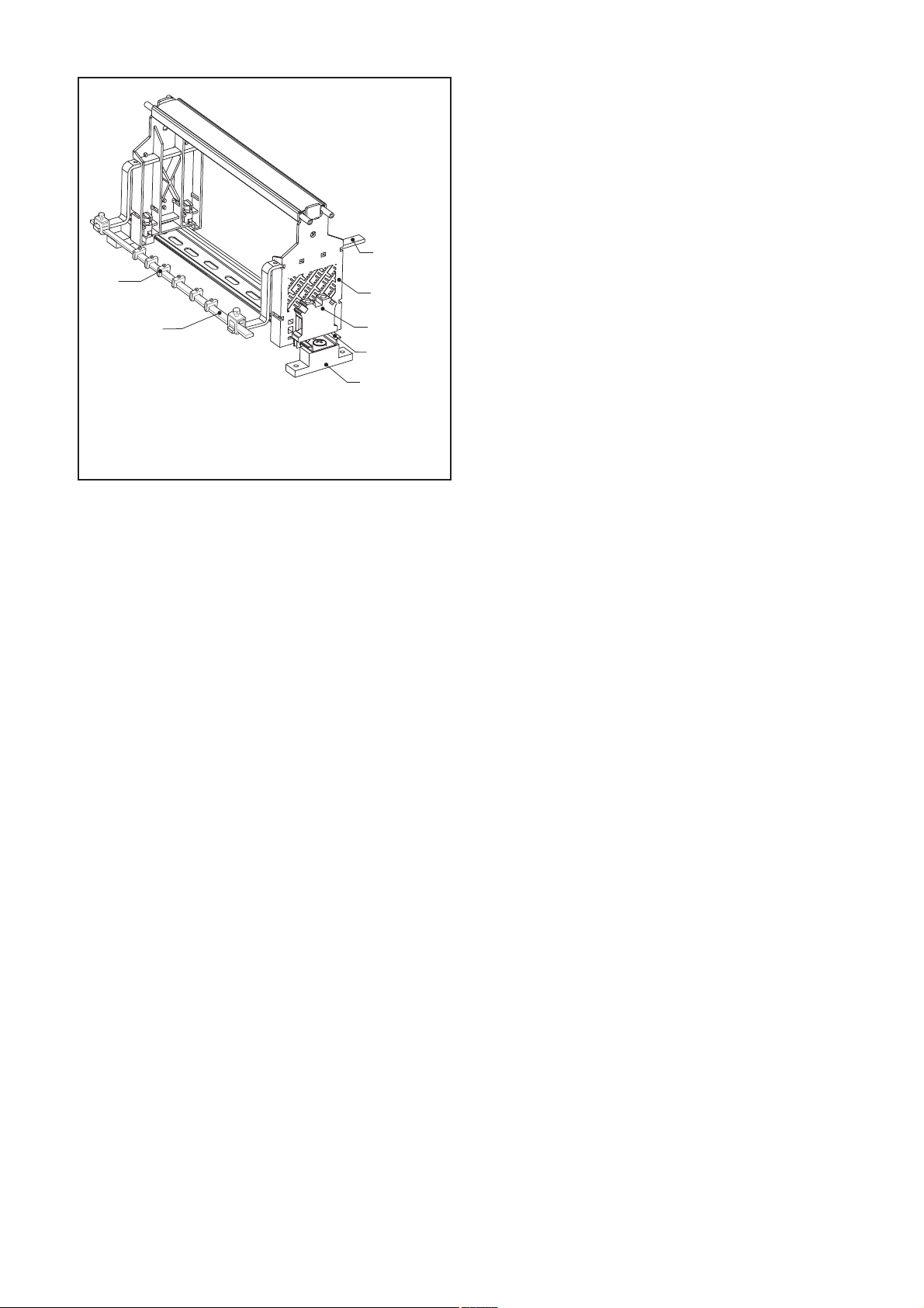
Figure 12: Mounting earthing and tagging accessories
Page 11

7
INM7700-6 Jan 2010
5 WIRING CONNECTIONS
5.1 General
This section describes wiring connections as follows:
a) Barrier connections Section 5.2
b) Connections to plant earth Section 5.3
c) Connections to dummy barriers Section 5.4
5.2 Barrier connections
Each barrier has 4 or 8 terminals, 2 or 4 on each side, allocated as
follows:
Safe area
Terminals 1,2,5 and 6 Safe-area power Sections
and signal lines 5.2.1 and
5.2.2
Hazardous area
Terminals 3,4,7 and 8 Hazardous-area Section
signal lines 5.2.1
Torque the screw terminals to 0.4Nm.
5.2.1 Signal line connections
Connect signal lines to the screw terminals at both sides of the barrier
(1 and 2 and/or 5 and 6 at the safe-area side, 3 and 4 and/or 7
and 8 at the hazardous-area side). The safe-area terminal 1 is also
used as a power connection when power is provided from the safe
area (see section 5.2.2 for details).
Clearly segregate hazardous-area and safe-area cabling as defined
by relevant codes of practice, and route cabling to the barriers
through clearly separated and identified conduits or trunking. Deal
with spare cable cores or screens as described in section 5.2.3.
Before making any signal connections from the hazardous area,
make sure any energy-storing devices (ie, devices NOT classified as
‘simple apparatus’) are certified as being compatible with the
barriers to which they will be connected. Check also that the
connecting cables conform with the cable types specified by the
safety documentation and that the maximum cable parameters
specified in MTL’s IS catalogue are not exceeded. In general, cable
parameters are unlikely to present problems except in installations
where cables longer than 500m are called for in IIC applications.
Do not connect barriers to safe-area equipment that is supplied from
(or contains) a source of potential with respect to earth that is greater
than 250V rms or 250V dc under normal or fault conditions, unless
this is specifically permitted by the safety documentation. This
limitation does not apply to safe-area equipment fed by a three-phase
440V neutral earth supply.
See Appendix A for examples of wiring connections for specific
applications.
5.2.2. Power supply connections general considerations
Take care that if barriers are connected to a safe-area power supply,
connections are made correctly. If the internal safety fuse blows, it will
destroy MTL7700 barriers. See Appendix A for specific connections
for individual barriers and applications.
5.2.3 Bussed Power applications and connections
When a number of barriers use a common power supply, the optional
power link (BPL7700) can be used. Typical applications include
hazardous-area switches, solenoids and 4–20mA transmitters; and
the barriers it can be used with are the MTL7706, MTL7707+,
MTL7787+, MTL7787P+ and MTL774x. See figure 14 for a typical
power link installation applied to hazardous-area switches.
Up to 40 barriers can be linked using the power links. The link itself
is supplied from a power feed module (MTL7798). The MTL7798
power feed module is provided with a trip circuit which protects the
barriers by switching off their supply if a fault (such as an
overvoltage) occurs in the power source. The state of the module is
indicated by one of two LED indicators:
a) Green ON when supply is normal and being passed
to the barriers.
b) Red ON when the trip mechanism is activated
indicating a fault.
After a fault has been indicated, the module can be reset by
disconnecting the main power supply.
Install the power links as follows (figure 13):
a) Mount an MTL7798 power feed module on the DIN-rail at one
end of the column of barriers being supplied.
b) Connect a safe-area 20–26V dc supply to terminals 5 and 6 of
the power feed module.
c) select the number of links required.
d) Lift the tag holders to gain access to the power link connectors
and insert the links (figure 13).
e) Close the tag holders.
f) To replace the barrier, lift the identifiers either side of the
appropriate barrier to check which one is linked, remove the
link, replace the barrier and re-insert the link and close the
identifiers.
WARNING
Do not remove bussed power links with power applied if
installed in FM Div 2
5.2.4 Spare cores/screens/0V returns: connections
Unused cores should be connected to 0V. Terminals on the earth foot
simplify this.
5.3 Connections to plant earth
5.3.1 General considerations
A barrier installation must be earthed properly for correct and safe
operation. Care must be taken that individual barriers are correctly
mounted so that the earth connection with the DIN-rail is secure.
An installation must, in turn, be connected to a suitable plant highintegrity earth. This should be done by connecting suitable conductors
to ETL7000 earth terminals (see section 5.3.2). It is also usually
advisable to make sure that the DIN-rail is isolated from any possible
enclosure earths by separating it from the mounting surface with
ISP7000 isolating spacers (see section 4.3.2).
BPL7700
power link
Figure 13: Power link insallation
Page 12

8
INM7700-6 Jan 2010
5.3.2 Earthing an installation
See figure 15. Connections from the DIN-rail to a suitable plant earth
are made from ETL7000 earth terminals. These clip onto the DIN-rail
as described in section 4.3.3 to make the vital earth connection with
the rail and the barriers. They are provided with two screw-clamp
terminals, to one of which a copper conductor to plant earth should
be connected. This should have a resistance no greater than 1Ω
though to increase safety and reduce interference, a resistance as
close to 0.1Ω as possible is preferable. The cross-sectional area of
the conductor should be as least 4mm
2
(12 AWG).
It is advisable to mount one ETL7000 earth terminal at each end of a
column of barriers to provide redundancy by connecting both
ETL7000 terminals to the plant earth. This makes it possible to
introduce a multimeter into one of the loops to measure loop
resistance without breaking the earth connection (figure 16) – a test
which should be done periodically. In these circumstances, resistance
for each cable loop should not exceed 2Ω.
The IS plant earth conductors should be clearly identified to warn
against unauthorised interference. Though not mandatory, it is
recommended that this should be done by winding blue insulating
tape round the conductors at intervals along their length.
WARNING
Do not use earth foot terminal as an IS earth termination.
Make IS earth connections using an ETL7000 earth
terminal as described in section 5.3.2.
5.3.3 Earthing an earth rail assembly
On installations which include earth rail assemblies (see section
4.3.4) an earth conductor, normally copper wire with a crosssectional area of at least 4mm
2
(12AWG) must be connected
between ETM7 earth terminals located at each end of the rail and the
‘spare’ terminals on the ETL7000 terminals at each end of the column
of barriers. See figure 17.
5.3.4 Hazardous-area equipment isolation
Hazardous-area equipment and interconnections should be isolated
from earth sufficiently to be capable of withstanding a 500V isolation
test. Such tests can, however, only be undertaken when the area is
gas free so it is fortunate that most circuits can be tested at low
voltages. To do this:
a) Disconnect from the barrier any cable connected directly to earth
or returned through a barrier with a nominal voltage of less than
10V.
b) Check the resistance to earth of the safe-area terminals with a
multimeter; it should be greater than 100kΩ.
Note: some hazardous-area equipment (eg, pH and conductivity
instrumentation) is unable to withstand this insulation test. As an
alternative, in these circumstances the system can comply with the
installation requirements described in IS sketch 121. See also
12.2.4.in BS EN 60079-14.
3
4
1
2
MTL7787+
MTL7787P+
Logic signal
1
5
MTL7798
(MTL7799)
3
4
1
2
MTL7706+
MTL7787+
MTL7787P+
250Ω
3
4
1
2
MTL7741
5
6
7
8
6
0V
0V
1-5V
}
Contact
signals
Power Bus
PB7700
Loop power to
opposite ends to
allow module
removal
Power
Connections
Hazardous
Area
Safe
Area
Figure 14: Typical application of the Power Bus
ETL7000 earth
terminal
To IS earth
Figure 15: Plant earth connection to ETL7000 earth terminal
ETL7000 earth
terminal
Loop
resistance
<2Ω
Local distribution transformer
Resistance meter or
bond integrity monitor
Figure 16: Earthing an installation with two conductors and
providing resistance test facilities
Page 13

9
INM7700-6 Jan 2010
5.3.5 Bonding practice when hazardous-area
equipment cannot meet prescribed insulation
standards
Where hazardous-area equipment is connected to earth (either
directly or indirectly) and/or it will not withstand a 500V insulation
test to ground or the alternative described in section 5.3.4, eg, straingauge bridges with low-voltage insulation, pH and conductivity
sensors, bare and/or earthed thermocouples, and some level
detectors, the following considerations apply:
Safety considerations
a) The pipe, vessel, or body of the hazardous-area apparatus
and/or the adjacent metallic structure must be connected to the
barrier DIN-rail (see item d) by a bonding conductor of at least
4mm2cross-sectional area for lengths of 100m or less; or at least
8mm2area for lengths between 100m and 200m.
b) Where bonding conductors are used, care must be taken to
avoid invading other intrinsically safe systems (those not using
bonding conductors) by elevation arising from currents which
may flow in the common earthing systems as a result of the
presence of the bonding conductor. Where this possibility
cannot be avoided, then barriers associated with bonded
systems should be mounted on a separate DIN-rail from those on
which other barriers are mounted. Additionally, the DIN-rails
themselves should also be earthed separately.
c) The hazardous-area equipment and/or adjacent metallic
structure bond connections must be secured against vibration
and corrosion. A terminal of the type used on ‘increased safety’
(‘e’) equipment is the mandatory solution.
d) The barrier DIN-rail connections must provide suitable
termination facilities for the bonding conductor and usual ‘earth
return’ by being equipped with separate increased safety (‘e’)
terminals.
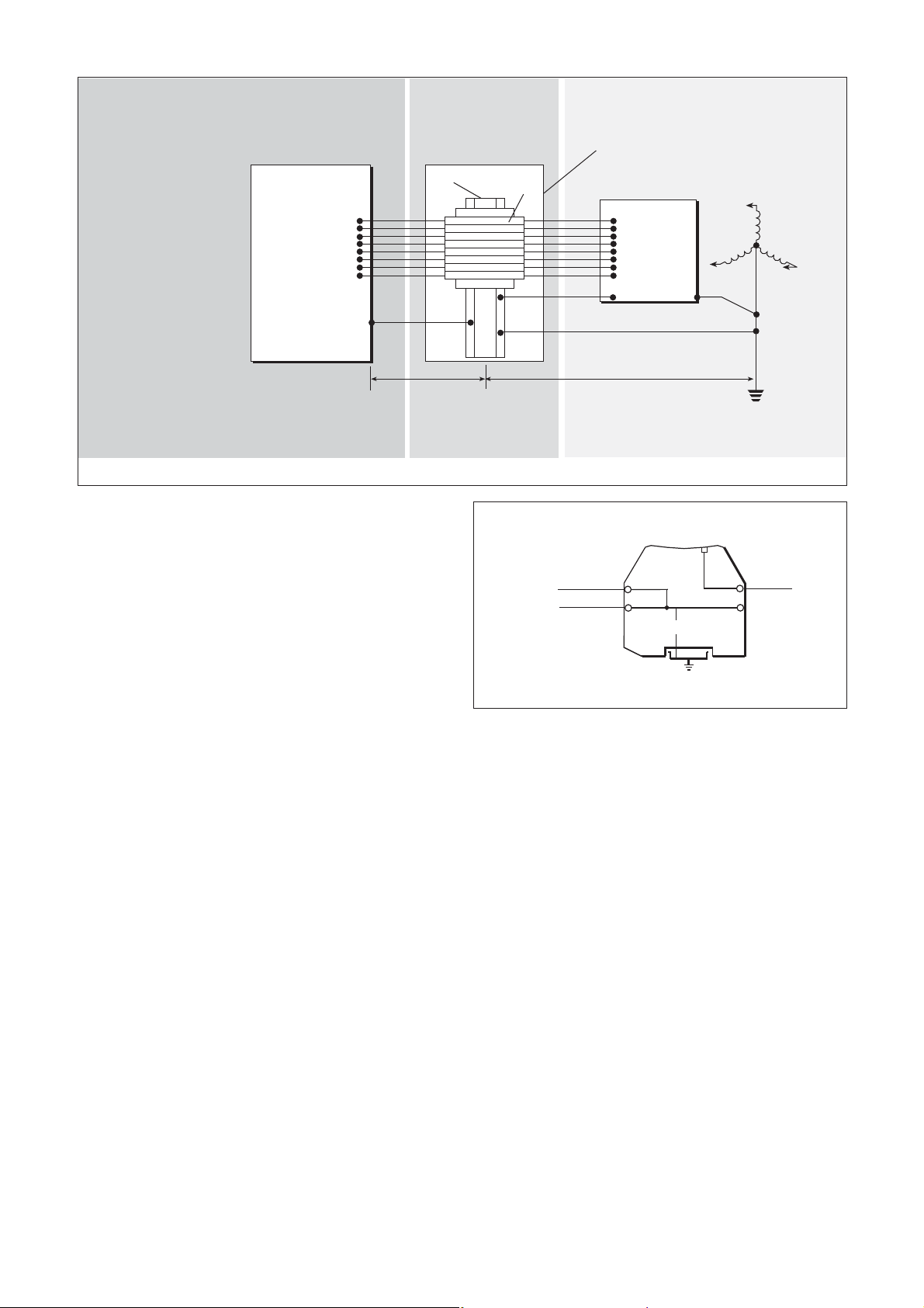
Operational requirements
e) Figure 18 shows the 0V rail of the safe-area equipment returned
to the barrier DIN-rail by a separate insulated conductor and the
structural earths of any safe-area equipment returned separately
to the neutral star-point. This reduces interference problems but
is not essential for safety reasons.
f) In general, the use of barriers in all measurement leads reduces
the possibility of earth circulating currents causing measurement
problems.
g) Resistance from the neutral star point to ‘terrestrial earth’ – via
the buried earth mat or rods – is determined by other regulations
and is not modified or determined by the intrinsic safety
requirements, which are concerned with the plant earth only.
5.4 Connections to dummy barriers
See figure 19. The MTL7799 dummy barriers provide safe
connection facilities for unused cable cores, cable screens and 0V
returns. In addition, safe-area terminals 2 and 1 are connected
internally to provide a straight ‘feedthrough’ 24V dc supply
connection, enabling the units to be used as feed modules for use
with a power bus, useful in applications where the fault trip
mechanism of the MTL7798 is not needed.
6 MAINTENANCE
6.1 General
Circuits in all MTL7700 Series barriers are encapsulated and so
cannot be repaired. However, provided they are correctly installed
and connected (as described in sections 4 and 5 of this manual) and
the circuits they protect are not themselves defective, barrier faults are
highly unlikely to occur. Therefore, servicing of barrier installations
consists mainly of routine inspection and earth testing as described in
this section.
More information about the maintenance of barrier installations is
given in BS EN 60079 -17.
6.2 Routine inspection
At intervals not exceeding two years (more frequently for harsh
environments), make a visual check of the barrier installation.
Personnel undertaking these checks should comply with all
regulations relating to the safety of plant and personnel. Care must
be taken to prevent any inadvertent direct connection between
hazardous- and safe-area circuits and, at all times, the safety
precautions discussed in section 3 MUST be observed.
TAG57
TGL7700
ERB57O
IMB57
ETL7000
ISP7000
ERL
(optional earth rail)
Cable screens
using earth rail
Cable screens
using module
terminals
ETM7
Figure 17: Earthing and screening using module earth terminals or earth rail alternative
Page 14
10
INM7700-6 Jan 2010
Check that:
a) Barriers are of the types and polarities specified in the safety
documentation.
b) The barriers are attached securely and correctly to the DIN-rail
to make sure the earth connection is safe.
c) There are no apparent signs of damage or corrosion to the
barriers, the ETL7000 earth terminals, the plant earth
connections, and, if fitted, any earth rail assemblies.
d) All hazardous-area and safe-area cable connections are made
correctly and the terminals properly tightened.
e) Interconnecting cables are of the type and rating specified by
the safety documentation and that they are not frayed or
otherwise damaged.
f) All earth returns and cable screens from the hazardous area are
connected to earth either through a barrier, a dummy barrier or
an earth rail.
g) Visually examine the earth conductors and make sure they are
not damaged in any way and that their terminations are secure
and free from corrosion.
h) Using a low-voltage low-current test meter (ie, a meter with an
output not exceeding 3V and 50mA), measure the resistance
between the DIN-rail and the neutral star-point of the supply and
make sure it does not exceed 1Ω. Record the reading and
compare it with readings taken during previous inspections. A
consistent reading repeated over a long period of time is a
reassuring sign indicating a sound earth return which is likely to
remain so. If two earth conductors are used as described in
section 5.3.2, the loop resistance should be measured as
described in that section and the reading should not be greater
than 2Ω.
WARNING: do not try to carry out a high-current earth
resistance test unless it is confirmed by the authority in
charge of the plant that the plant is gas-free.
7 FAULT-FINDING
7.1 Introduction
Most barrier-protected systems are relatively simple and their
operation is easy to check. However, when fault finding is necessary,
it must only be undertaken after checking with plant personnel
responsible for safety that it is safe to proceed.
The fault-finding procedures described in this section call for the use
of a digital multimeter – this being the most common type used.
However, other types can be used provided their characteristics when
measuring silicon diodes are known.
Many digital multimeters include a diode test function which is useful
when diode chains are included in the test. These usually operate by
passing 1mA through the diode and measuring the voltage across it.
When measuring more than two diode drops in series, note that the
full-scale range of some multimeters is only 2V on the diode test
range. With three or more diode drops it is therefore possible that the
meter may indicate over-range. In the test tables (tables 4 to 10),
section 8, any drop of more than 4V is indicated as infinity (∞).
Zener diodes and ordinary silicon diodes have a typical forward
voltage drop of approximately 0.6V/diode. Diode return paths with
Schottky diodes have a typical voltage drop of <0.3V for each diode
in the chain, eg, MTL7787+, 7787P+.
Figure 20 depicts a typical switch-status transfer circuit protected by
an MTL7787+ barrier which illustrates some of the fault-finding
techniques discussed in this section. To determine the serviceability of
MTL7700 Series barriers, follow the steps described in sections
7.2 to 7.3.
Hazardous-area
equipment
incapable of
withstanding
insulation test
Safe-area
equipment
0V
Local
distribution
transformer
1Ω maximum
Safe area
Hazardous area
(Zone 2)
or safe area
Hazardous area
Zone 0, 1 or 2
Bonding conductor
<100m: 4mm
2
minimum
100 200m (maximum): 8mm
2
minimum
Enclosure
DIN-rail
Barriers
Figure 18: Bonding practice where hazardous-area equipment cannot meet required standards of insulation from earth
1
2
3
4
MTL7799
Unused cable
cores and
screens
24Vdc
Bussed power
Figure 19: MTL7799 dummy barrier connections
Page 15

11
INM7700-6 Jan 2010
7.2 Power supply check
Check that the power supply to an individual barrier circuit (or to an
MTL7798 power feed module or an MTL7799 dummy barrier
sourcing the power bus ) is functional and that the voltage across the
supply with respect to earth is correct. For example, in Figure 20 the
presence of 24V on terminal 1 and 12V on terminal 2 when the
switch in the hazardous area is closed confirms the serviceability of
almost the complete circuit.
7.3 Barrier resistance test
To test the resistance of a barrier on site, refer to figure 20 and carry
out the following procedure:
a) Unplug hazardous-area cables from terminals 3 and 4.
b) Unplug safe-area cables from terminals 1 and 2.
WARNING: Take care when handling safe-area cables;
the relay contacts in figure 20 for example could be
carrying mains voltage.
c) Measure the end-to-end resistance of the barrier by connecting a
digital multimeter (set to a suitable Ω range) between terminals
1 and 3. The reading should typically be slightly less (eg 1–3%
lower) than the maximum end-to-end resistance listed in tables 4
to 10 for the appropriate barrier type or approximately 10–20%
higher than the figure specified in the safety description.
d) Check the functioning of the diode-return channel (MTL7787+,
7787P+, only) by selecting the diode test function on the
multimeter and connecting it between terminals 4 (+ve) and 2
(–ve). This measures the forward voltage drop of the Schottky
diodes in the chain: the reading should be less than 0.9V.
Repeat the test with the connections reversed (ie, terminals 4
(–ve) and 2 (+ve) for an expected reading of ∞ for the reverse
voltage drop.
e) Tests c) and d) confirm the continuity of both barrier channels. If
either channel is open-circuit it is most likely that the fuse has
blown. The safe-area circuit should be investigated in an attempt
to discover the cause of the fault.
Note: if the barrier is removed, make sure the safe-area and
hazardous-area cables disconnected during operations a) and b)
are connected to an earth-rail, a dummy barrier or insulated
completely.
c) If it is not possible to disconnect wiring to the barrier for steps a)
and b), carry out the tests given in table 4.
8 EQUIPMENT AND BARRIER TESTS
8.1 Thermocouple and RTD tests
8.1.1 Thermocouple circuit testing
Thermocouple test and calibration equipment is rarely certified
intrinsically safe and therefore requires special authorisation before it
can be used for testing or calibrating thermocouple circuits in
hazardous areas. To overcome this problem, the thermocouple
circuits can be protected by using an MTL7760ac barrier as shown
in figure 21. This permits the thermocouple output to be measured
without needing special authorisation to use uncertified thermocouple
test equipment.
As it is seldom possible to measure accurately the temperatures of
thermocouples located in hazardous areas, a safe way of adjusting
calibration tables to compensate for plant temperatures is needed.
This can be done by disconnecting the compensating cables from the
thermocouple, shorting them together, and measuring the temperature
of the shorting point.
8.1.2 Resistance temperature detector (RTD) circuit
testing
Resistance temperature detector (RTD) circuits can be tested by
disconnecting the measuring leads from the RTD head in the
hazardous area and connecting them to a resistance box. Sometimes
it is more convenient to connect the resistance box in the safe area,
for instance at point ‘xx’ in figure 22. For the latter method, however,
the RTD must be shorted out or an allowance made for its
temperature. The effect of a negative temperature change can be
simulated by connecting the resistance box into the measurement lead
at point ‘yy’. The advantage of connecting the resistance box at the
RTD head is that any leakage can also be determined by connecting
the resistance box at point ‘yy’.
8.2 Barrier tests
8.2.1 General
MTL7700 Series barriers do not need to be subjected to routine
testing if they are in normal use. Generally, the inspection tests
described in section 6 are more than adequate. However, if the
performance of barriers is in any way suspect, then carry out the
detailed tests described in this section. Barriers which pass these tests
satisfactorily are highly unlikely to represent an unacceptable level of
risk or cause a circuit malfunction.
There are two types of test (as shown by tables 4 to 10); a simple test
using a digital multimeter to test barriers on site and a more
comprehensive bench test using a constant current source to establish
the breakdown characteristics.
Although certification requirements concentrate on pulse-current tests,
in many ways the leakage current tests described in this section are
a more satisfactory method of testing suspect diodes. If a complete
functional check of a barrier is needed, then the multimeter and
constant current tests described in sections 8.2.2 and 8.2.3 should be
made although, for most purposes, the multimeter tests should suffice.
1
2
3
4
370Ω
+24Vdc
12V
0V
400Ω
12V
relay
Plant earth via DIN-rail
30mA
MTL7787+
Figure 20: Switch-status transfer circuit using an MTL7787 barrier
1
2
3
4
1
2
3
4
Compensating cables
Safe-area
equipment
Calibration
equipment
MTL7760ac
Figure 21: Calibrating a thermocouple barrier circuit
Page 16

12
INM7700-6 Jan 2010
8.2.2 Multimeter tests
See tables 4 to 10. The use of a digital multimeter for testing barriers
is described in section 7. The tables assume that the multimeter is set
to a suitable Ω range for the end-to-end resistance tests (except for
diode return channels) and for the continuity tests; and that the
multimeter diode test function is used for the diode tests, channel
isolation tests and for the end-to-end resistance tests for diode return
channels.
8.2.3 Constant-current tests
For these tests (last column of tables 4 to 10) a constant-current
generator capable of supplying 10µA, 20mA and 40mA currents
from a 30V source is needed. Ideally, a purpose-built current
generator should be used but, alternatively, a set-up based on a
laboratory power supply and two multimeters (figure 23) will serve.
The current is measured by one multimeter and trimmed by adjusting
the output voltage of the power supply indicated on the second
multimeter.
When using a constant-current generator for testing MTL7700 Series
barriers, note the following points:
a) The current must be limited to 50mA to avoid damaging the
barriers.
b) The accuracy of the current is not critical and can vary by ±5%.
c) Test leads must be connected securely to the barrier terminals;
however, the changeover switch and current selector reduce the
need for connection changes.
d) Using a high resistance in series with the barrier gives more
stable results and makes it easier to set the required current.
8.3 Tests for Active Barriers
8.3.1 Tests for the MTL7706+
Comprehensive testing requires specialised equipment, beyond the
scope of on-site tests. However, an effective test which will confirm
that the unit is operating correctly is shown in figure 24. Ammeter 1
measures the transmitter simulator current of between 4 and 20mA
flowing from terminal 4 and the safe-area load current flowing to
terminal 4 simultaneously. Since these two currents are equal and
opposite, the resulting reading on the ammeter should be virtually
zero. Ammeter 2 verifies the presence of the 4–20mA transmitter
signal.
1
2
3
4
5
7
Bridge supply
Measurement
Safe-area
equipment
MTL7756ac
Variable
resistance
Measurement
Variable
resistance
yy x
x
Figure 22: Calibrating an RTD barrier circuit
To barrier on test
Digital
multimter
(current)
Digital
multimter
(voltage)
current
selector
current limited
to 30mA
2-channel laboratory power supply
0 - 30V
variable
0 - 30V
variable
+ -
+ -
Changeover
switch
40mA
20mA
10mA
3MW
1.5kW
750W
Figure 23: Constant-current test circuit using a power supply
and digital multimeters
1
2
3
4
A1
A2
Transmitter
simulator
4-20mA
250W
+20 to
35Vdc
MTL7706+
+
+
_
_
Figure 24: MTL7706+ test circuit
8.3.2 Tests for the MTL7707+
Since this unit incorporates a built-in protection circuit, it has to be
tested in a different manner to an ordinary shunt-diode barrier.
Referring to figure 25, set the transmitter simulator to 4mA and to
20mA, and check that the ammeter reads approximately the same
value. Then, having set the simulator to 20mA, check that the voltage
between terminals 1 and 3 is less than 8.5V and between terminals
2 and 4 is less than 1.6V.
Figure 25: MTL7707+ test circuit
1
2
3
4
A
MTL7707+
Transmitter
simulator
4-20mA
+20 to
35Vdc
250W
+
_
Page 17

13
INM7700-6 Jan 2010
Input Output Line Fault
Open circuit Open Closed
Short circuit Closed Closed
620Ω Closed Open
10KΩ Open Open
8.3.3.2 Testing MTL7742 Barriers
The MTL7742 is a single channel switch/prox input barrier with an
open collector solid state interface to the safe area equipment. To
verify correct operation proceed as follows:
a) Connect the barrier as shown in figure 27.
b) Check that the LED is on when the input switch is closed, and off
when the input switch is open.
8.3.3.3 Testing MTL7743 Barriers
The MTL7743 is a dual channel switch/prox input barrier, each
channel with a relay interface to the safe area equipment. To verify
correct operation proceed as follows:
a) Connect the barrier as shown in figure 28.
b) With an ohmeter, check that the output contacts (terminal 1 & 2)
close when the input switch for channel 1 is closed.
c) Repeat the procedure for channel 2.
8.3.3.4 Testing MTL7744 Barriers
A dual channel version of the MTL7742, this module provides two
solid state interfaces for prox/switch inputs. To verify correct
operation proceed as follows:
a) Connect the barrier as shown in figure 29.
b) Connect power via the power bus
c) Check that the LED is on when the input switch is closed for
channel 1, and off when the input switch is open for channel 1.
d) Repeat the procedure for channel 2.
8.3.3.5 Testing MTL7745 Barriers
This module is a single channel interface for prox/switch inputs with
line fault detection. To verify correct operation proceed as follows:
a) Connect the barrier as shown in figure 30.
b) With an ohmeter, check the status of the output contacts
according to Table 3
3
4
1
2
MTL7742
5
6
7
8
Bussed Power
24V
Vs+
Vs-
}
2KΩ
Figure 27: Test circuit for MTL7742
3
4
1
2
MTL7745
5
6
620W10kW
24V
Bussed Power
Line Fault
Output
Vs+
Vs
Figure 30: Test circuit for MTL7745
Table 3 Test conditions for MTL7745
3
4
1
2
MTL7743
5
6
7
8
Bussed Power
24V
Vs+
Vs
Channel 1
Channel 2
Channel 1
Channel 2
Figure 28: Test circuit for MTL7743
3
4
1
2
MTL7744
5
6
7
8
Bussed Power
24V
Vs+
Vs-
2KW
2KW
Channel 1
Channel 2
Channel
1
Channel
2
Figure 29: Test circuit for MTL7744
8.3.3 Tests for MTL774x
The MTL774x range are switch/prox input barriers with a choice of
changeover relay contacts or a solid state switch acting as the safe
area interface. Relay contacts provide a universal interface capable
of switching a wide range of signals including ac, low level and high
level voltages. Phase reversal is achieved by connecting the normally
open or normally closed contacts as required. The solid state switch
variants can be configured to switch from a power rail or down to
ground and makes these barriers ideal for high switching frequency
applications.
When testing bus powered barriers use either an MTL7798 Power
Feed module or an MTL7799 dummy barrier for direct ‘feed-through’
connection of a 24V dc supply.
8.3.3.1 Testing MTL7741 Barriers
The MTL7741 is a single channel switch/prox input barrier with
changeover relay contacts acting as the safe area interface. To verify
correct operation proceed as follows:
a) Connect the barrier as shown in figure 26.
b) With an ohmeter, check that the output contacts (terminal 5 & 6)
close when the input switch is closed.
3
4
1
2
MTL7741
5
6
7
8
Bussed Power
24V
Vs+
Vs
Output
Figure 26: Test circuit for MTL7741
Page 18

14
INM7700-6 Jan 2010
BARRIER DATA MULTIMETER TESTS CONSTANT-CURRENT TESTS
MTL Safety End-to-end Diode Diode Terminal Terminal
model Description Resistance Test Test Voltage Voltage
No.
ΩΩ
+ve -ve @ 10μμA @ 20mA
V
ΩΩ
mA Min Max Min Max Min Max
7710+ 10 50 200 62 75 ∞ Vf
z
x 1 6 9.5 6.6 9.7
7715+ 15 100 150 110 119 ∞ Vf
z
x 1 12 13.6 12.4 13.7
7715P+ 15 50 291 59 64 ∞ Vf
z
x 1 12.6 13.3 13 13.4
7722+ 22 150 147 159 174 ∞ Vf
z
x 2 19.6 20.9 19.7 21.1
7728+ 28 300 93 311 333 ∞ Vf
z
x 2 25.9 26.5 26 26.7
7728- 28 300 93 311 333 Vf
z
x 2 ∞ 25.9 26.5 26 26.7
7728P+ 28 237 119 241 252 ∞ Vf
z
x 3 24.9 25.5 25 25.6
7729P+ 28 164 170 171 184 ∞ Vf
z
x 3 24.9 25.5 25 25.6
8.4 Test tables for passive barriers
Tables 4 to 10 detail the tests for all MTL7700 Series ‘passive’ barriers. In the ‘diode test’ columns, the figures adjacent to the diode description
indicate the number of forward-biased diodes used in the barrier chain. Using the multimeter diode test function and knowing the diode voltage
drop figures (approximately 0.6V for each Zener diode and 0.3V for each Schottky diode), the expected reading across the diode chain can
be determined.
BARRIER DATA MULTIMETER TESTS CONSTANT-CURRENT TESTS
MTL Safety End-to-end Diode Diode Terminal Terminal
model Description Resistance Test Test Voltage Voltage
No.
ΩΩ
+ve -ve @ 10μμA @ 20mA
V
ΩΩ
mA Min Max Min Max Min Max
7758+ 7.5 10 750 14 17 ∞ Vf
z
x 1 6 6.9 6.6 7
7758- 7.5 10 750 14 17 ∞ Vf
z
x 1 6 6.9 6.6 7
7764+ 12 1k 12 1010 1050 ∞ Vf
z
x 1 10 11.4 10.5 11.6
7767+ 15 100 150 110 119 ∞ Vf
z
x 1 12 13.6 12.4 13.7
7779+ 28 300 93 311 333 ∞ Vf
z
x 2 25.9 26.3 26 26.5
7796+ 26 300 87 311 333 ∞ Vf
z
x 2 23.9 24.4 24 24.6
7796+ (ch2) 20 390 51 401 428 ∞ Vf
z
x 2 18.3 18.8 18.4 19
7796- 26 300 87 311 333 Vf
z
x 2 ∞ 23.9 24.4 24 24.6
7796- (ch2) 20 390 51 401 428 Vf
z
x 2 ∞ 18.3 18.8 18.4 19
7788+ 28 300 93 311 333 ∞ Vf
z
x 2 25.9 26.4 26 26.6
7788+ (ch2) 10 50 200 62 75 ∞ Vf
z
x 1 6 9.5 6.6 9.7
7788R+ 28 300 93 311 333 ∞ Vf
z
x 2 25.9 26.4 26 26.6
7788R+ (ch2) 10 50 200 62 75 V
r
V
r
0 0 6.2 6.8
Table 4: Single channel polarised barriers
Table 5: Dual channel polarised barriers
Note: Vfzis the voltage dropped by a forward biased zener diode - 0.6V typically
V
r
is the voltage dropped by the sense and current limit resistors - 3.2V for a typical 1mA test current
Page 19

15
INM7700-6 Jan 2010
Table 6: Single channel
BARRIER DATA MULTIMETER TESTS CONSTANT-CURRENT TESTS
MTL Safety End-to-end Diode Diode Terminal Terminal
model Description Resistance Test Test Voltage Voltage
No.
ΩΩ
+ve -ve @ 10μμA @ 20mA
V
ΩΩ
mA Min Max Min Max Min Max
7728ac 28 300 93 311 333 ∞∞25 26.7 25.6 27.2
BARRIER DATA MULTIMETER TESTS CONSTANT-CURRENT TESTS
MTL Safety End-to-end Diode Diode Terminal Terminal
model Description Resistance Test Test Voltage Voltage
No.
ΩΩ
+ve -ve @ 10μμA @ 20mA
V
ΩΩ
mA Min Max Min Max Min Max
7761ac 9 90 100 98 107 ∞∞6 8.6 6.9 8.9
7761Pac 9 350 26 361 378 ∞∞6.8 8.6 7.7 8.9
7764ac 12 1k 12 1010 1050 ∞∞10 11.6 10.8 11.9
7766ac 12 150 80 159 174 ∞∞10 11.6 10.8 11.9
7766Pac 12 75 157 84 92 ∞∞9.6 10.9 10.4 11.2
Table 7: Dual-channel ac barriers
BARRIER DATA MULTIMETER TESTS CONSTANT-CURRENT TESTS
MTL Safety End-to-end Diode Diode Terminal Terminal
model Description Resistance Test Test Voltage Voltage
No.
ΩΩ
+ve -ve @ 10μμA @ 20mA
V
ΩΩ
mA Min Max Min Max Min Max
7760ac 10 50 200 62 75 ∞∞6 9.5 6.9 9.8
7765ac 15 100 150 112 124 ∞∞12 14.1 12.7 14.4
7778ac 28 600 47 614 651 ∞∞24.0 24.4 25.4 26.0
Table 9: Dual-channel star-connected ac barriers
BARRIER DATA MULTIMETER TESTS CONSTANT-CURRENT TESTS
MTL Safety End-to-end Diode Diode Terminal Terminal
model Description Resistance Test Test Voltage Voltage
No.
ΩΩ
+ve -ve @ 10μμA @ 20mA
V
ΩΩ
mA Min Max Min Max Min Max
7755ac 3 10 300 15 19 Vf
d
x 3 Vfdx 3 1 2.1 1.8 2.4
7756ac 3 10 300 15 19 Vf
d
x 2 Vfdx 2 0.7 1.4 1.2 1.6
Table 8: 2/3 channel low voltage ac barriers
Note: Vfdis the voltage dropped by a forward biased rectifier diode - 0.6V typically
Page 20

16
INM7700-6 Jan 2010
BARRIER DATA MULTIMETER TESTS CONSTANT-CURRENT TESTS
MTL Safety End-to-end Diode Diode Terminal Terminal
model Description Resistance Test Test Voltage Voltage
No.
ΩΩ
+ve -ve @ 10μμA @ 20mA
V
ΩΩ
mA Min Max Min Max Min Max
7787+ 28 300 93 311 333 ∞ Vf
z
x 2 26.6 27.4 26.7 27.6
7787+ (ch2) 28 — — ∞ (+)
0.9V + 26 ∞ Vf
z
x 2 26.6 27.4 26.7 27.6
7787P+ 28 237 119 241 253 ∞ Vf
z
x 3 26.4 27.4 26.5 27.6
7787P+ (ch2) 28 — — ∞ (+)
0.9V + 26 ∞ Vf
z
x 2 26.6 27.4 26.7 27.6
7789+ 38 300 93 614 651 ∞ Vf
z
x 2 26.6 27.4 26.7 27.6
7789+ (ch2) 28 — — ∞ (+)
0.9V + 26 ∞ Vf
z
x 2 26.6 27.4 26.7 27.6
Table 10: Diode return barriers
Note: Vfzis the voltage dropped by a forward biased zener diode - 0.6V typically
Page 21

17
INM7700-6 Jan 2010
APPENDIX A: TYPICAL WIRING CONNECTIONS
FOR SPECIFIC APPLICATIONS.
Hazardous
Area
Safe
Area
3
4
1
2
250W4 -20mA
Power +26V
Signal
Power Bus
1-5V
MTL7706+
MTL7787+
MTL7787P+
MTL7788+
Hazardous
Area
Safe
Area
3
4
1
2
MTL7788R+
250Ω
1-5V
Power +26V
Power Bus
Figure A1: 2-wire transmitters
Hazardous
Area
Safe
Area
3
4
1
2
MTL7789+
7
8
5
6
Power +26.6V
Power +26.6V
Logic signal
Logic signal
Power Bus
Figure A5: 2-channel switch inputs
Hazardous
Area
Safe
Area
3
4
1
2
MTL7756ac
Receiver
7
5
3
4
1
2
MTL7755ac
Receiver
Figure A6: Low-level analogue inputs (RTD’s)
Figure A2: 2-wire transmitters with 250Ω conditioning
Hazardous
Area
Safe
Area
3
4
1
2
MTL7760ac
MTL7765ac
MTL7778ac
Recorder
Controller
Data logger
Computer
Compensating cable
Figure A3: Thermocouple/mV input
Hazardous
Area
Safe
Area
3
4
1
2
MTL7743
MTL7744
7
8
5
6
Logic signal
Logic signal
Power
Figure A7: 2-channel switch/proximity input
Hazardous
Area
Safe
Area
3
4
1
2
MTL7742
5
6
Logic signal
Logic signal
Power Bus
+20V - 35V
0V
Figure A8: Single channel switch/proximity input
Hazardous
Area
Safe
Area
3
4
1
2
MTL7787+
MTL7787P+
Power +26.6V
Signal
Power Bus
Figure A4: 2-wire transmitter/switch input
Page 22

18
INM7700-6 Jan 2010
Hazardous
Area
Safe
Area
3
4
1
2
MTL7728+
0V
+26V
P
I
Figure A9: Analogue output
Hazardous
Area
Safe
Area
3
4
1
2
+7V
3
4
1
2
MTL7761ac
MTL7764ac
3
4
1
2
MTL7761ac
--7V
0V
Output (mV)
Sense
+
—
Figure A13: Strain-gauge bridges
Hazardous
Area
Safe
Area
3
4
1
2
MTL7745
5
6
620Ω
10kΩ
+22.9 - 30V
LFD
COM
CH 1
Power Bus
Figure A10: Single channel switch/proximity input with Line
Fault Detect
Hazardous
Area
Safe
Area
3
4
1
2
MTL7789+
7
8
5
6
Power +26V
Power +26V
Power Bus
Figure A11: Low power digital outputs
Hazardous
Area
Safe
Area
3
4
1
2
MTL7741
5
6
7
8
NO
COM
Power Bus
22.9V - 30V
NC
Figure A12: Single channel switch/proximity input with cutout
relay
Page 23

Page 24

MTL Instruments Pty Limited
9 /12 Billabong Street
Stafford
Queensland 4053
Australia
Tel: + 61 1300 308 374 Fax: + 61 1300 308 463
E-mail: enquiries@mtlaus.com.au
MTL Canada Safety Instrumentation
#102, 4249 97 Street
Edmonton, Alberta
Canada T6E 5Y7
Tel: +1 780 485 3132 Fax: +1 780 485 3122
E-mail: cinfo@mtlnh.com
MTL Instruments China Co. Ltd.
Room 1002A, The Gateway
No 10 Yabao Road, Chaoyang District
Beijing 100020
China
Tel: +86 010 8562 5718/5720/5721 Fax: +86 010 8562 5725
E-mail: bjsales@mtl-inst.cn
MTL Instruments sarl
Les Carrés du Parc
10 rue des Rosiéristes
69410 Champagne au Mont d’Or
France
Tel: +33 (0)4 78 64 98 32 Fax: +33 (0)4 78 35 79 41
E-mail: info@mtl-inst.fr
MTL Instruments GmbH
An der Gümpgesbrücke 17
D-41564 Kaarst
Germany
Tel: +49 (0)2131 718930 Fax: +49 (0)2131 7189333
E-mail: info@mtl.de
MTL India
No. 36, Nehru Street
Off Old Mahabalipuram Road
Sholinganallur
Chennai - 600 119
India
Tel: + 91 (0)44 24501660/24501857 Fax: + 91 (0)44 24501463
E-mail: sales@mtlindia.com
MTL Italia srl
Via Cantù 11
I - 20092 Cinisello Balsamo MI
Italy
Tel: +39 (0)2 61802011 Fax: +39 (0)2 61294560
E-mail: info@mtl-inst.it
MTL Instruments KK
MT Building 3F
2-7-5 Shiba Daimon
Minato-ku Tokyo
Japan 105-0012
Tel: +81 (0)3 6430 3128 Fax: +81 (0)3 6430 3129
E-mail: sales@mtlkk.co.jp
MTL Instruments BV
MTL Instruments BV
Terheijdenseweg 465
4825BK Breda
The Netherlands
Tel: +31(0)76 7505360 Fax: +31(0)76 7505370
E-mail: info@mtlbenelux.com
Cooper Crouse-Hinds Pte Ltd
No.2 Serangoon North Avenue 5
#06-01 Fu Yu Building
Singapore 554911
Tel: +65 6 487 7887 Fax: +65 6 487 7997
E-mail: sales@mtlsing.com.sg
MTL Instruments
Villa No. 4, Sector 2-17, Street 6
PO Box 53234,
Abu Dhabi, UAE
Tel: +971 2 446 6840 Fax: +971 2 446 6841
E-mail: mtlgulf@mtl-inst.com
Measurement Technology Limited
Great Marlings, Butterfield, Luton, Beds
England LU2 8DL
Tel: +44 (0)1582 723633 Fax: +44 (0)1582 422283
E-mail: enquiry@mtl-inst.com
MTL Incorporated
3413 N. Sam Houston Parkway W.
Suite 210
Houston TX 77086
USA
Tel: +1 281 571 8065 Fax: +1 281 571 8069
E-mail: csinfo@mtl-inst.com
Group Internet home page http://www.mtl-inst.com/
Members of The MTL Instruments Group
 Loading...