

Dwyer Instruments Magnesense II MS2-X102, Magnesense II MS2-X103, Magnesense II MS2-X101, Magnesense II MS2-X111, Magnesense II MS2-X112 Installation And Operating Instructions Manual
Page 1
Bulletin P-MS2
[88.90]
21/32
®
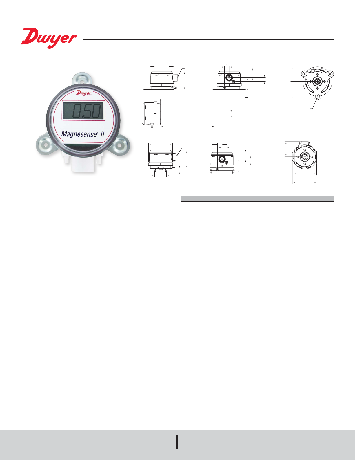
Series MS2 Magnesense® II Differential Pressure Transmitter
Specications - Installation and Operating Instructions
ø3-7/16
[ø87.31]
Duct Mount Bracket
ø3-7/16
[ø87.31]
1-41/64
[41.71]
The Series MS2 Magnesense® II Differential Pressure Transmitter combines the
proven stable Piezo sensing technology of our original Series MS with additional
features to reduce installation time and simplify ordering. In this second generation
transmitter, we have added additional eld selectable pressure ranges so that each
model can have four selectable ranges along with four additional bidirectional ranges.
When using the pluggable integral display or the portable remote display tool, both
Metric and English engineering units can be selected via on board dip switches. Dual
current and voltage outputs allow users to simultaneously take either a current or
voltage output to their building controller and have a local test circuit for verication of
the output reading. The voltage output can be selected to be either 0 to 5 VDC or 0 to
10 VDC, while the current is always 4 to 20 mA. Both the current and voltage output
can also be inverted. Alternatively, the MS2 can be ordered with either a BACnet
or MODBUS
chained together.
Like the original Series MS, the second generation transmitter can be used as a linear
pressure output or a linear velocity output with the square root extraction done in
the transmitter. Additional parameters have been included to expand the square root
capability to include ow measurements.
BACnet
nodes in any segment to 32. Therefore, the transceiver may be rated at one unit load.
Fractional loads are also acceptable. The MS2 accounts as an eighth of a load on the
MSTP network.
INSTALLATION
Surface Mount:
The transmitter should be mounted on a vertical surface with the connections directed
down to prevent moisture from entering either the pressure ports or the electrical cable
entry. The diaphragm must be vertical to minimize gravity effects on the diaphragm.
Attach the mounting ange to a at surface using three #8 x 1/2˝ pan head sheet metal
screws. Do not over tighten.
®
Communications protocol that will allow the transmitters to be daisy-
®
and Modbus® Communications protocol recommend limiting the number of
[16.55]
21/32
1/2 NPT
2-41/64
[67.16]
7-41/64[194.06]
1/2 NPT
2-41/64
[67.24]
25/64
[9.97]
SPECIFICATIONS
Supported Baud Rates: 9600, 19200, 38400, 57600, 76800, 115200.
Data Size: 8.
Parity: None.
Stop Bits: 1.
Service: Air and non-combustible, compatible gases.
Wetted Materials: Consult factory.
Accuracy: ±1% FS for 0.25˝ (50 Pa), 0.5˝ (100 Pa), 2˝ (500 Pa), 5˝ (1250 Pa), 10˝
(2 kPa), 15˝ (3 kPa), 25˝ (5 kPa); ±2% FS for 0.1˝ (25 Pa), 1˝ (250 Pa), ±0.1˝ (±25
Pa), ±1˝ (±250 Pa) and all bi-directional ranges.
Stability: ±1% / year FSO.
Temperature Limits: 0 to 150°F (-18 to 66°C).
Pressure Limits: 1 psi max., operation; 10 psi burst.
Power Requirements: 10 to 35 VDC (2 wire), 17 to 36 VDC or isolated 21.6 to 33
VAC (3 wire).
Output Signals: 4 to 20 mA (2-wire), 0 to 5 VDC, 0 to 10 VDC (3-wire).
Response Time: Averaging 0 to 240 sec, 2.5 Hz sample rate, 1.5 to 228 sec for
95% step change.
Zero & Span Adjustments: Digital push buttons.
Loop Resistance: Current output: 0 to 1250Ω max; Voltage output: Min. load
resistance 1kΩ.
Current Consumption: 40 mA max.
Display (optional): 5-digit LCD.
Electrical Connections: 3-wire removable European style terminal block for 16 to
26 AWG.
Electrical Entry: 1/2˝ NPS thread; Accessory (A-151): Cable gland for 5 to 10 mm
diameter cable.
Process Connection: 3/16˝ ID tubing (5 mm ID); Max. OD 9 mm.
Enclosure Rating: IP66.
Mounting Orientation: Diaphragm in vertical position.
Weight: 8.0 oz (230 g).
Agency Approvals: CE.
[16.55]
Wall Mount Bracket
15/64
[6.00]
21/32
[16.51]
57/64
[22.60]
DIN Mount Bracket
57/64
[22.67]
21/32
[16.51]
29/32
[23.02]
[12.76]
29/32
[23.02]
1/2
[12.77]
[3] 3/16 [4.76] HOLES
EQUALLY SPACED ON A
1/2
2-11/64
[55.25]
2-9/16
[65.12]
4.115 [104.52] B.C.
2-11/64
[55.12]
3-11/32
[84.84]
3-1/2
Duct Mount:
The transmitter should be mounted away from fans, corners, heating and cooling coils
and other equipment that will effect the measurement of the pressure.
1. To mount the transmitter, drill a .562˝ (12.70 mm) diameter hold into the duct.
2. Insert transmitter probe into the duct.
3. Mark location of three mounting holes on duct using mounting ange as template.
Drill holes.
4. Attach mounting ange to duct with three #8 x 1/2˝ pan head sheet metal screws.
Do not over tighten screws.
DWYER INSTRUMENTS, INC.
P.O. BOX 373 • MICHIGAN CITY, INDIANA 46360, U.S.A.
Electrical Connection:
The Series MS2 simultaneously transmits a 2-wire 4 to 20 mA current output and
a 3-wire 0 to 5 V / 0 to 10 V voltage output via a removable European-style three
conductor terminal block. The transmitter can be wired in one of the following three
ways to utilize the current and / or voltage output. The range of the voltage output can
be selected using the on board dip switches as described in the Dip Switch Settings
section of this manual.
Modbus® is a registered trademark of Schneider Automation, Inc.
Phone: 219/879-8000
Fax: 219/872-9057
www.dwyer-inst.com
e-mail: info@dwyermail.com
Page 2
Power Supply
AC
AC/DC JUMPER
CURRENT OUTPUT WIRING
Refer to the below table for the required supply rating.
Output Type Power Supply Rating
2-wire current
3-wire voltage
Simultaneous current and voltage
10 to 40 VDC (40 mA min)
17 to 40 VDC or 21.6 to 33 VAC (40 mA min)
17 to 40 VDC (40 mA min)
Choose a power supply with a voltage and current rating sufcient to meet the power
specications under all operating conditions. If the supply is unregulated, make sure
that the output voltage remains within the required voltage range under all power line
conditions. Ripple on the supply should not exceed 100 mV.
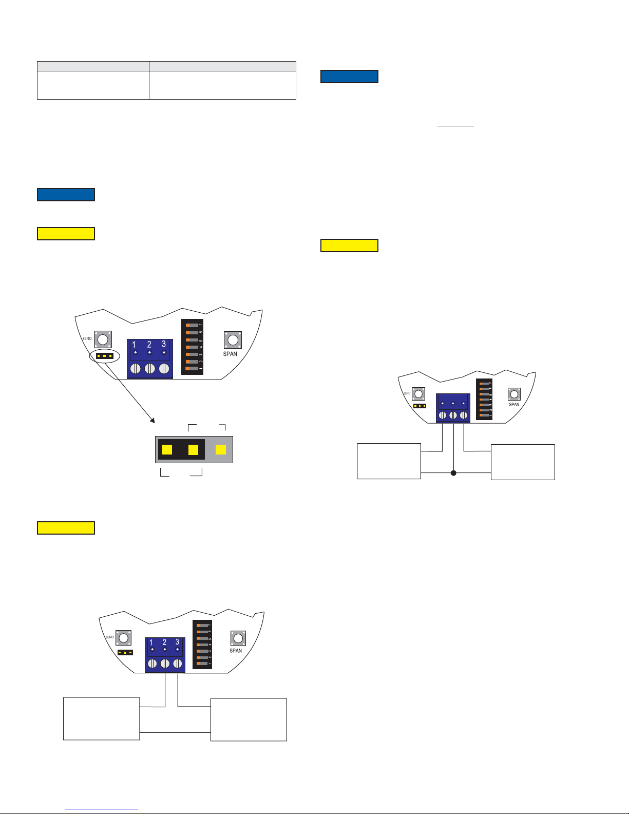
AC/DC Jumper Selection
NOTICE
The jumper is factory set to AC. If DC power is applied while
the jumper is set to AC, no damage will occur. However, the
accuracy of the unit may temporarily be affected.
CAUTION
Powering the unit with AC power while the jumper is set to DC
may permanently damage the transmitter.
Refer to Figure 1 for the location of the AC / DC jumper. Place the shorting jumper
across either the two pins marked AC or the two pins marked DC.
The range of appropriate receiver load resistances (RL) for the power supply voltage
available is given by the formula listed below. Shielded 2-wire cable is recommended
for control loop wiring. Ground the shield at the power supply end only.
NOTICE
The receiver may be connected to either the negative or positive
side of the loop, whichever is most convenient. Should polarity
of the transmitter or receiver be inadvertently reversed, the loop will not function
properly but no damage will be done to the transmitter.
ps - 10.0
V
L =
R
20 mA DC
The maximum length of connecting wire between the transmitter and the receiver is
a function of wire size and receiver resistance. That portion of the total current loop
resistance represented by the resistance of the connecting wires themselves should
not exceed 10% of the receiver resistance. For extremely long runs (over 1,000 feet),
it is desirable to select receivers with lower resistances in order to keep the size and
cost of the connecting leads as low as possible. In installations where the connecting
run is no more than 100 feet, connecting lead wire as small as No. 22 ga. can be used.
3-Wire 0 to 10 V and 0 to 5V Voltage Operation
CAUTION
DO NOT EXCEED SPECIFIED SUPPLY VOLTAGE RATINGS.
PERMANENT DAMAGE NOT COVERED BY WARRANTY
WILL RESULT.
The connection to the transmitter are made to Terminals 1, 2, and 3 on the terminal
block as shown in Figure 3. The terminal block is removable and each of the terminals
are labeled underneath the terminal block on the circuit board. Polarity is indicated by
PWR, COM, and +VOUT. When connecting using a DC power source, make sure the
AC/DC selection jumper is set for DC. If the polarity of the transmitter is inadvertently
reversed, the unit will not function properly, but no damage will be done to the
transmitter. When connecting to an AC power source, make sure the AC/DC selection
jumper is set for AC. Either lead of the supply power may be connected to PWR and
COM without affecting the operation of the transmitter or damage to the transmitter.
DC
Figure 1
2-Wire 4 to 20 mA Current Operation
CAUTION
DO NOT EXCEED SPECIFIED SUPPLY VOLTAGE RATINGS.
PERMANENT DAMAGE NOT COVERED BY WARRANTY
WILL RESULT. SIMULTANEOUS OUTPUTS ARE NOT DESIGNED FOR AC
VOLTAGE OPERATION.
The connections to the transmitter are made through terminals 2 and 3 on the terminal
block as shown in Figure 2. The terminal block is removable and each of the terminals
are labeled underneath the terminal block on the circuit board. Polarity is indicated by
+IOUT and -IOUT. The AC/DC selection jumper should be set for DC operation.
3
2
1
RECEIVER
+
_
+
POWER
_
VOLTAGE OUTPUT WIRING
Figure 3
The minimum receiver load is 1K Ω. The resistance due to the wire should be low
compared to the receiver load resistance. While the voltage at the terminal block
remains unchanged with a 10 mA current ow, resistive losses in the wiring do cause
errors in the voltage delivered to the receiver. For a 1% accurate gauge, the resistance
of the wires should be less than 0.1% of the value of the receiver load resistance. This
will keep the error caused by the current ow below 0.1%.
The output across +VOUT and COM will be either 0 to 5 V, 0 to 10 V, or the inverse
depending on the dip switch setting. See Dip Switch Setting Section for more
information.
+
_
Figure 2
+
POWERRECEIVER
_
Page 3
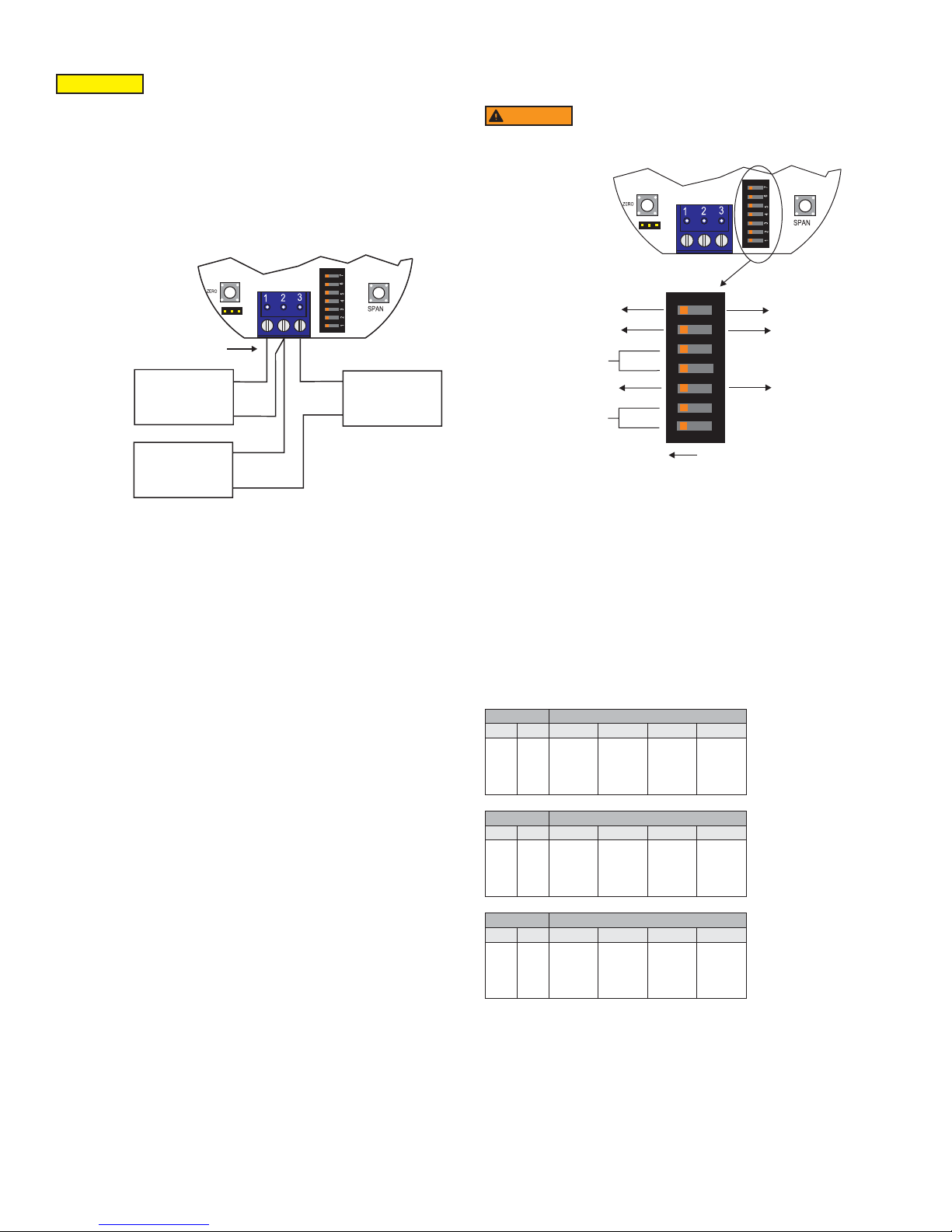
Simultaneous Current and Voltage Operation
VOLTAGE OUTPUT WIRING
NOT
VOL
MUST
WIRES
WIRED
ON
DIP SWITCH SETTINGS
CAUTION
DO NOT EXCEED SPECIFIED SUPPLY VOLTAGE RATINGS.
PERMANENT DAMAGE NOT COVERED BY WARRANTY
WILL RESULT. SIMULTANEOUS OUTPUTS ARE NOT DESIGNED FOR AC
VOLTAGE OPERATION.
The connection to the transmitter are made to Terminals 1, 2, and 3 on the terminal
block as shown in Figure 4. The terminal block is removable and each of the terminals
are labeled underneath the terminal block on the circuit board. Polarity is indicated by
PWR, COM, and +VOUT. The AC/DC selection jumper should be set for DC operation.
The voltage output and the power supply must have separate wire leads that are only
joined at terminal 2 of the transmitter. Additional error may occur for the voltage output
if a single wire is used or if the wires are joined at the power supply or receiver.
- POWER AND
TAGE RECEIVER “-”
BE SEPERATE
AND BOTH
TO
_
+
CURRENT
RECEVIER
VOLTAGE
RECEVIER
+
_
_
POWER
+
SIMULTANEOUS CURRENT AND
Figure 4
For the current output, the maximum allowable loop resistance (wiring + receiver
resistance) is dependent on the power supply. The maximum loop voltage drop must
not reduce the transmitter voltage below 17 V. The maximum loop resistance can be
calculated using the following equation:
R
MAX = (VPS – 17.0) / 0.02 Where VPS is the power supply voltage
The equation uses 17.0 instead of 10.0 used in current only equation. This represents
the minimum voltage supply which is higher on the simultaneous output conguration
due to the requirements of the voltage outputs.
Shielded 4-wire cable is recommended for control loop wiring. Ground the shield
at the power supply end only. Should the polarity of the transmitter or receiver be
inadvertently reversed, the unit will not function properly, but no damage will be done
to the transmitter.
DIP SWITCH SETTINGS
DIP Switches can be located next to the terminal block as shown in Figure 5. A small
screw driver or pen can be used to change the position of the switches.
WARNING
All power should be turned off to the transmitter before adjusting
the dip switch settings to avoid electrical shock.
DIR
10V
UNITS
UNIDIRECTIONAL BIDIRECTIONAL
7
6
5
4
3
RANGE
REV
5V
2
1
Figure 5
Factory Settings
Mode = Unidirectional (except on MS2-XX1X models)
Range = Highest Range Setting (0.5, 5, or 28 in w.c.)
Units = Inches W.C.
Voltage Output Range = 10 V
Direct / Reverse Output Action = Direct
Setting the Pressure Range
Ranges are selected by adjusting DIP Switch Positions 1 and 2 according to the
below tables. The range also depends on the units selected (Refer to Setting the
Engineering Units Section) and if the input is set for unidirectional or bidirectional
(Refer to the Setting for Unidirectional or Bidirectional Section). The tables below show
the maximum full scale value for the selected range and selected units. If the unit is set
to unidirectional, the ranges are all zero based. If the unit is set for bidirectional, the
ranges will be ± the maximum full scale value shown in the tables below.
DIP Switch Full Scale Range for MS2-X101
1 2 in w.c. Pa mm w.c. kPa
OFF
OFF
OFF
ON
ON
ON
OFF
ON
0.1
0.15
0.25
0.5
25
40
50
125
2.5
4
6
10
0.025
0.040
0.050
0.125
For voltage outputs, the minimum receiver load is 1K Ω. The resistance due to the
wire should be low compared to the receiver load resistance. While the voltage at
the terminal block remains unchanged with a 10 mA current ow, resistive losses in
the wiring do cause errors in the voltage delivered to the receiver. For a 1% accurate
gauge, the resistance of the wires should be less than 0.1% of the value of the receiver
load resistance. This will keep the error caused by the current ow below 0.1%.
The output across +VOUT and COM will be either 0 to 5 V, 0 to 10 V, or the inverse
depending on the dip switch setting. See Dip Switch Setting Section for more
information.
DIP Switch Full Scale Range for MS2-X102
1 2 in w.c. Pa mm w.c. kPa
OFF
OFF
OFF
ON
ON
ON
OFF
ON
1
2
3
5
250
500
750
1250
25
50
75
125
0.250
0.500
0.750
1.25
DIP Switch Full Scale Range for MS2-X103
1 2 in w.c. Pa mm w.c. kPa
OFF
OFF
OFF
ON
ON
ON
OFF
ON
10
15
25
28
2500
3500
5000
6975
250
350
500
700
2.50
3.50
5.00
6.98
Setting for Unidirectional or Bidirectional
The Models MS2-X101 and MS2-X102 models are unidirectional only. The Bidirectional
models MS2-X103, MS2-X111 and MS2-X112 can be changed to measure pressure in
one direction at a reduced accuracy by changing the setting of DIP Switch 3.
• When the switch is in the ON direction, the transmitter will be set for Unidirectional
and will be 0 based (i.e. 0 to 5 in w.c.).
• When the switch is in the OFF position, the transmitter will be set for Bidirectional
and will be ± the maximum of the selected range (i.e. ±5 in w.c.).
• For unidirectional units only, switch has no effect and unit will remain in unidirectional
mode.
Page 4

Setting the Engineering Units
Magnesense
®
II comes with the selection of four engineering units (in w.c., Pa, mm
w.c., or kPa). The engineering units are selected using DIP Switch 4 and 5. The units
will be displayed on the optional LCD display.
DIP Switch Units
4 5 Pressure Velocity Air Flow
OFF
OFF
OFF
ON
ON
ON
OFF
ON
kPa
mm w.c.
Pa
in w.c.
m/s
m/s
m/s
FPM
m
m
m
cfm
3
/h
3
/h
3
/h
Setting the Output Voltage Range
Voltage output can be either 0 to 10 V or 0 to 5 V depending on the position of DIP
Switch 6.
• When the switch is in the ON position, the output will be 0 to 10 V
• When the switch is in the OFF position, the output will be 0 to 5 V
Setting the Input / Output Action
The output will either directly or indirectly follow the input based on the position of DIP
Switch 7.
• When the switch is in the ON position, the output directly follows the input (i.e. output
increases as the input increases)
• When the switch is in the OFF position, the output acts in reverse of the input (i.e.
output decreases as the input increases)
Another option for models that do not have a display would be to use a Model A-435-A
remote display tool which can plug into the connector shown in Figure 7. The remote
display tool has two buttons that function identically to the buttons on the PCB.
CALIBRATION
NOTICE
There is a 5 second delay from the time the zero or span
calibration buttons is released until the time that the change in
calibration takes place. This delay is used to prevent stress related offsets on the
lower ranges.
NOTICE
The security level that is set in the Programming Menu Section
of the manual will determine which calibrations, if any, may be
adjusted by the user.
Zero Calibration
The zero calibration can be set by applying zero pressure to both the pressure ports
and pressing the zero button for 3 seconds. If either the remote or local LCD is present,
the display will read ZEro and then sequence back to the home display.
SPAN Calibration
The span calibration can be adjusted only after setting the zero adjustment. It must
be completed within 5 minutes of the last zero calibration. The span calibration button
will be ignored until the zero calibration is completed. Apply pressure to the ports of
the transmitter that is associated with the maximum output of the transmitter (20 mA,
5 V, or 10 V depending on output being used). Press and hold the span button for 3
seconds. If either the remote or local LCD is present, the display will read SPAn and
then sequence back to the home display. If the span calibration is attempted before
adjusting the zero calibration, the FAIL error message will ash on the display. On bi-
directional models, separate spans can be performed on the positive and negative
sides of the range.
LCD DISPLAY
The Magnesense
®
II can be ordered with an optional, integral LCD. If the display is
not needed for normal operation, the transmitter can be ordered without the LCD.
An A-MS2-LCD eld upgradeable display is available. It comes with a housing cover
with the overlay cut out for the display. The display will plug into the pins as shown in
Figure 6.
Figure 7
Display Error Messages
ovEr = The applied pressure is greater than the maximum span value causing an Over
Range Error.
UndEr = The applied pressure is less than the minimum span value causing an Under
Range Error.
FAiL = When the span or zero buttons are pressed, the pressure value is out of the
range to allow a correct setting. This may be due to a sensor failure or incorrect
pressure being applied.
Err1 = The sensor is damaged.
PROGRAMMING MENUS
Home Menu
During normal operation, the display will be in the Home Menu and will display the
current measured pressure and the engineering units.
Menu Access Security
While in the Home Menu, press and hold the Zero and Span buttons simultaneously
until SECUr appears on the display in order to access the other programming menus.
Upon releasing the buttons, the display will indicate the current security level.
If the current security level is the security level desired (i.e. Security Level 0), press
and hold the span button for three seconds to enter the Pressure, Velocity, or Air Flow
Menu.
If the security level is not the desired level, the security level can be changed
temporarily to a lower security level or permanently to a higher level of security by
pressing the zero button. A security code will be shown on the display and it can be
changed to one of the codes listed in the below table. The span button chooses which
digit and the zero button increments the value of that digit. Pressing and holding the
span button will store the value.
Figure 6
Security
Level Setting
0
1
2
3
Access
View Menu Edit Menu Span Zero
000
111
222
333
Yes
Yes
No
No
Yes
No
No
No
Yes
No
No
No
Yes
Yes
Yes
No
The level of access to the programming menus and the calibration is limited based on
the security level. The above table details the level of access for each security level.
Page 5

Mode Selection / Digital Dampening Menu
From the home display, pressing the span and zero button simultaneously for 3
seconds will access the Menu Security Level. If the level is set to 0 or 1, pressing and
holding the span button for 3 seconds a second time will access the Mode Selection
Menu. The display will default to Pressure when rst powered up. Pressing the zero
button will cycle to Velocity and Flow.
FACTORY DEFAULT PROCEDURE
In order to reset all of the menu settings back to their factory programmed values,
press and hold both the span and zero buttons simultaneously for 10 seconds until
FACt is displayed on the LCD. Upon releasing the buttons, the unit will be factory
defaulted. Since resetting the transmitter will wipe out all changes, it is necessary to
zero (and possibly span) the transmitter before taking measurements.
Once the desired Mode is displayed, pressing and holding the span button for three
seconds will save the selected mode and display the digital dampening or averaging
parameter. This parameter stabilizes the output and the display by averaging the
readings. There are 2.5 readings taken each second and the user can select the
number of seconds that they would like to average up to 240 seconds. The display and
the output will continue to update at a rate of 2.5 updates per second, but the moving
average is used for these updates.
PRESSURE MODE
Maximum Output Adjustment
If the Pressure Mode was selected, pressing and holding the span after adjusting the
digital dampening will enter the Pressure Mode. In this menu, the maximum output
pressure (POH) can be adjusted to any pressure between the lowest dip switch range
to the highest dip switch range. If the dip switch settings are preferred over manually
setting the range, the POH parameter can be set to off.
VELOCITY MODE
K-Factor Adjustment
If the Velocity Mode was selected, pressing and holding the span after adjusting the
digital dampening will enter the Velocity Mode and the transmitter will display the
engineering unit that has been selected by the dip switch. Pressing and holding the
span button for three seconds will enter the K – Factor adjustment. The K – Factor can
be adjusted between 0.001 to 9.999. The K-Factor can be adjusted by pressing the
span button to select the digit and pressing the zero button to increment the value of the
digit. Pressing and holding the span button for three seconds will enter the Maximum
Output Adjustment parameter.
Maximum Output Adjustment
The maximum output can be equivalent to a velocity or a pressure. After adjusting
the K-Factor, the display will indicate if the adjustment is set for pressure or velocity.
Pressing the zero button will toggle between the selections. Pressing and holding the
span button for three seconds will enter the maximum output adjustment. The maximum
output can be adjusted by pressing the span button to select the digit and pressing the
zero button to increment the value of the digit. Pressing and holding the span button for
three seconds will save this value and go to the Security Update Menu.
FLOW MODE
K-Factor Adjustment
If the Flow Mode was selected, pressing and holding the span after adjusting the digital
dampening will enter the Flow Mode and the transmitter will display the engineering unit
that has been selected by the dip switch. Pressing and holding the span button for three
seconds will enter the K – Factor adjustment. The K – Factor can be adjusted between
0.001 to 9.999. The K-Factor can be adjusted by pressing the span button to select
the digit and pressing the zero button to increment the value of the digit. Pressing and
holding the span button for three seconds will enter the Area Adjustment parameter.
MAINTENANCE/REPAIR
Upon nal installation of the Series MS2 Magnesense
®
II Differential Pressure
Transmitter, no routine maintenance is required besides zeroing the transmitter
occasionally. Besides routine calibration and installation of the LCD, the Series MS2
is not eld serviceable and it is not possible to repair the unit. Field repair should not
be attempted and may void warranty.
WARRANTY/RETURN
Refer to “Terms and Conditions of Sales” in our catalog and on our website. Contact
customer service to receive a Return Goods Authorization number before shipping the
product back for repair. Be sure to include a brief description of the problem plus any
additional application notes.
APPENDIX I
Air Velocity / Air Flow Calculations
Velocity is calculated using the below equation:
Velocity(fpm) = K-Factor x 4004.4 x √(Diff. Press. (in of w.c.)
Velocity in m/s is then calculated from the equation:
Velocity(m/s) = Velocity(fpm) x 0.00508
Flow is calculated using the below equation:
Flow(cfm) = Area(Ft
3
Flow (m
/h) = Flow (cfm) x 1.6992
2
) x K-Factor x 4004.4 x √(Diff. Press. (in of w.c.)
APPENDIX II
Maximum Flow
Range
in w.c.
0.5
5
28
Max Displayed Flow Max (K Factor x Area)
CFM M
5885000
5885000
5885000
3
/H CFM Mode M3/H Mode
9999000
9999000
9999000
2037.2
644.2
272.2
154.5
59.9
25.3
Area Adjustment
For Flow applications, the area is multiplied by the velocity to determine the volumetric
air ow. The area will be listed in either feet or meters depending on the dip switch
settings. The units will be indicated on the display at the time of adjustment.The area
can be adjusted by pressing the span button to select the digit and pressing the zero
button to increment the value of the digit. Pressing and holding the span button for three
seconds will enter the Maximum Output Adjustment parameter.
Maximum Output Adjustment
The maximum output can be equivalent to a ow or a pressure. After adjusting the
Area parameter, the display will indicate if the adjustment is set for pressure or ow.
Pressing the zero button will toggle between the selections. Pressing and holding the
span button for three seconds will enter the maximum output adjustment. The maximum
output can be adjusted by pressing the span button to select the digit and pressing the
zero button to increment the value of the digit. Pressing and holding the span button for
three seconds will save this value and go to the Security Update Menu.
Security Update / Save Changes Menu
The Security Update Menu allows the security level to be set either higher or lower than
the current security level setting. This security level will be displayed the next time the
Menus are accessed from the home screen. Pressing the zero button cycles through
the security levels. Pressing and holding the span button for three seconds accepts
the new security level and gives the option to save all the menu changes. Pressing the
zero button will toggle between yes and no. Yes will save the changes made to all menu
items and no will discard all the changes made to all menu items. If the display is set
to yes, pressing and holding the span will save the menu items and return the display
to the Home Position.
Page 6

APPENDIX III
BUTTON PRESS LEGEND
MODE
PRESSURE
OR
TO"PRESSURE, VELOCITY, OR FLOW"MENUS
Quick Start Guide
MENU FLOW CHART
ZERO
PRESS ZERO BUTTON
=
SPAN
PRESS SPAN BUTTON
=
ZERO
PRESS AND HOLD ZERO BUTTON
=
SPAN
PRESS AND HOLD SPAN BUTTON
=
ZERO
PRESS AND HOLD ZERO AND SPAN BUTTONS
=
SPAN
MENU CONVENTIONS
IN HOME POSITION:
ZERO
CALIBRATE UNIT TO ZERO PRESSURE.
SPAN
CALIBRATE UNIT TO SPAN PRESSURE.
ZERO
ENTER MENU DISPLAY
SPAN
DISPLAY IS NOT NECESSARY
IN MENU DISPLAY:
SPAN
SEQUENCES TO NEXT MAIN MENU ITEM, AND IF A MENU ITEM IS CHANGED TEMPORARILY SAVES THE SELECTION
ZERO
SEQUENCES THROUGH SUB MENU SELECTIONS OR INCREMENTS DIGITS
SPAN
SEQUENCE TO NEXT DIGIT. ACTIVE DIGIT WILL BLINK.
BLINKING DIGIT
=
3
SECURITY LEVEL
SELECTION
SELECTION
, VELOCITY,
FLOW
ADJUST AV ERAGING
0.0
in
C
W
ZERO
SPAN
SECUr
SEC 0
SPAN
PrES
SPAN
000
A
VG
SPAN
HOME POSITION
WHILE BUTTONS ARE
PRESSED
WHEN BUTTONS ARE
RELEASED DISPLAYS CURRENT
SECURITY LEVEL
ZERO
TO CHANGE
SECURITY LEVEL
IF SECURITY IS SET TO
0,1, OR 2
S 345
SPAN
LoCK
ZERO
ZERO
SPAN
INCREMENT
DIGIT
SELECT
DIGIT
uEL
HOLD 7
SECONDS
ZERO
SPAN
INCREMENT
ZERO
DIGIT
SELECT
SPAN
DIGIT
IF SECURITY IS SET TO 3
PRESS ANY KEY
OR WAIT 5 SECONDS
ZERO
FLo
FACTORY SETTINGS
RESTORED, THEN RETURNS
TO HOME POSITION
FACt
SECURITY LEVEL
0
1
2
3
HOME POSITION
ZERO
SPAN SPANSPAN
SETTING
000
111
222
333
0.0
in
C
W
TO SELECT MODE
Page 7

FROM AVERAGING MENU
PRESSURE MODE MENU
SWITCH
FROM
VELOCITY MODE MENU
AND SAVE " MENU
SELECT
SET
VELOCITY
PoH
ADJUST PRESSURE
OUTPUT HIGH
"
AdJ
SELECTED UNITS
DISPLAYED
"
P
MENUS
TO " UPDATE SECURITY
AND SAVE " MENU
FROM AVERAGING MENU
Unit
SPAN
UPON RELEASE
PoH n
SPAN
THIS MENU DEPENDS ON
DIP SWITCH SETTING
FP
M
SPAN
PoH = DIP SWITCH FULL SCALE SETTING
SET PoH TO DESIRED VALUE
ZERO
PoH Y
SPAN
288
in
W
SPAN
UNITS SELECTED
OR
Unit
M
S
BY DIP SWITCH
SETTING
C
ZERO
INCREMENT
ZERO
DIGIT
SELECT
SPAN
DIGIT
UNITS SET BY DIP
WILL BLINK
ADJUST DISPLAY
K FACTOR
MAXIMUM OUTPUT
BY PRESSURE OR
ADJUST VELOCITY
OUTPUT HIGH
diSP
K
o AdJ
uoH
TO " UPDATE SECURITY
SPAN
UPON RELEASE
SPAN
UPON RELEASE
SPAN
UPON RELEASE
d1000
SPAN
AdJ
SPAN
0233
FP
M
FPM OR M/S BASED
ON DIP SWITCH SETTING
0233
SPAN
K
ZERO
u
K
K
M
S
ZERO
SPAN
ZERO
SPAN
AdJ
INCREMENT
DIGIT
SELECT
DIGIT
INCREMENT
DIGIT
SELECT
DIGIT
P
ZERO
SPAN
TO PoH , PRESSURE
MODE MENU
Page 8

FROM " UPDATE SECURITY
AND SAVE " MENU
UPDA
LEVEL
TE SECURITY
SAVE CHANGES
©Copyright 2018 Dwyer Instruments, Inc. Printed in U.S.A. 6/18 FR# 444021-00 Rev. 8
DWYER INSTRUMENTS, INC.
P.O. BOX 373 • MICHIGAN CITY, INDIANA 46360, U.S.A.
SEC 0
SPAN SPAN
SAuE
in
W
C
HOME POSITION
0.0
ZERO
SEC 1 SEC 2
UPON RELEASE
SPAN
ZERO
no
Phone: 219/879-8000
Fax: 219/872-9057
ZERO
SEC 3
SPAN
ZERO
ZERO
SPAN
YES
ZERO
SPANSPAN
www.dwyer-inst.com
e-mail: info@dwyermail.com
 Loading...