

Page 1
BULLETIN NO.A-27
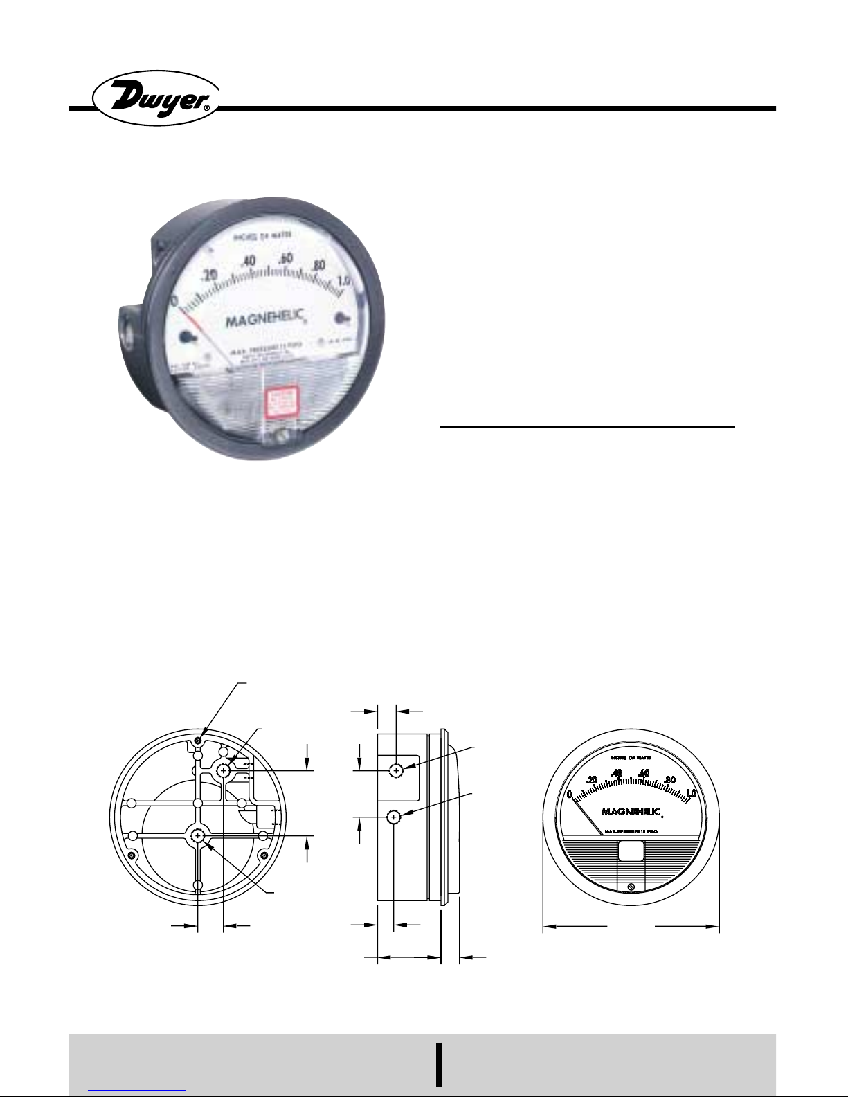
Magnehelic® Differential Pressure Gage
OPERATING INSTRUCTIONS
SPECIFICATIONS
Dimensions: 4-3/4 dia. x 2-3/16 deep.
Weight: 1 lb. 2 oz.
Finished: Baked dark gray enamel.
Connections: 1/8 NPThigh and low pressure
taps, duplicated, one pair side and one
pair back.
Accuracy: Plus or minus 2% of full scale, at
70°F. (Model 2000-0, 3%; 2000-00, 4%).
Pressure Rating: 15 PSI (0,35 bar)
Ambient Temperature Range: 20° to 140°F
(-7 to 60°C).
Standard gage accessories include two 1/8
NPT plugs for duplicate pressure taps,
two 1/8 NPTpipe thread to rubber tubing
adapters, and three flush mounting
adapters with screws.
Caution: For use with air or compatible
gases only.
For repeated over-ranging or high cycle rates,
contact factory.
Not for use with Hydrogen gas. Dangerous
reactions will occur.
DWYER INSTRUMENTS, INC.
P.O. BOX 373 • MICHIGAN CITY, INDIANA 46361 U.S.A.
Phone: 219/879-8000 www.dwyer-inst.com
Fax: 219/872-9057 e-mail: info@dwyer-inst.com
Lit-by-Fax: 888/891-4963
11/16
[17.46]
1/8 NPT LOW
PRESSURE
7/16
[11.11]
1-11/16
[42.86]
1/2
[12.70]
1/8 NPT LOW
PRESSURE
1/8 NPT HIGH
PRESSURE
1/2
[12.70]
1/8 NPT HIGH
PRESSURE
Ø4-1/8 [104.78] BOLT
CIRCLE FOR PANEL MOUNTING
120° APART
1-1/4
[31.75]
Ø4-3/4
[120.65]
1-3/4
[44.45]
Page 2
1.Select a location free from excessive vi-
bration and where the ambient temperature
will not exceed 140°F. Also, avoid direct
sunlight which accelerates discoloration of
the clear plastic cover. Sensing lines my be
run any necessary distance. Long tubing
lengths will not affect accuracy but will increase response time slightly. Do not restrict lines. If pulsating pressures or vibration cause excessive pointer oscillation,
consult the factory for ways to provide additional damping.
2. All standard Magnehelic gages are cali-
brated with the diaphragm vertical and
should be used in that position for maximum accuracy. If gages are to be used in
other than vertical position, this should be
specified on the order. Many higher range
gages will perform within tolerance in other
positions with only rezeroing. Low range
Model 2000-00 and metric equivalents
must be used in the vertical position only.
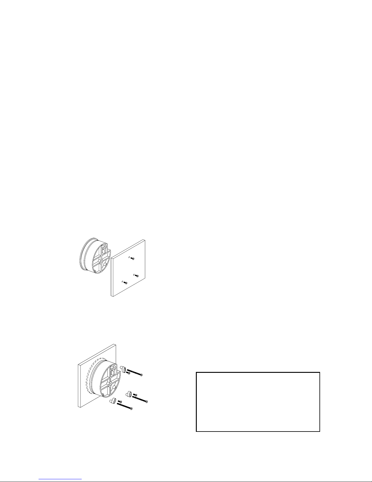
3. Surface Mounting
Locate mounting holes, 120° apart on a 41/8
⬙ dia. circle. Use No. 6-32 machine
screws of appropriate length.
4. Flush Mounting
Provide a 4-9/16⬙ dia. opening in panel.
Insert gage and secure in place with No. 632 machine screws of appropriate length,
with adapters, firmly secured in place. To
mount gage on 1-1/4
⬙-2⬙ pipe, order op-
tional A-610 pipe mounting kit.
MAGNEHELIC®INSTALLATION
5. To zero the gage after
installation
Set the indicating pointer exactly on the
zero mark, using the external zero adjust
screw on the cover at the bottom. Note that
the zero check or adjustment can only be
made with the high and low pressure taps
both open to atmosphere.
Operation
Positive Pressure:Connect tubing from
source of pressure to either of the two high
pressure ports. Plug the port not used. Vent
one or both low pressure ports to atmosphere.
Negative Pressure: Connect tubing from
source of vacuum or negative pressure to
either of the two low pressure ports. Plug
the port not used. Vent one or both high
pressure ports to atmosphere.
Differential Pressure: Connect tubing
from the greater of two pressure sources to
either high pressure port and the lower to
either low pressure port. Plug both unused
ports.
When one side of the gage is vented in
dirty, dusty atmosphere, we suggest an A331 Filter Vent Plug be installed in the open
port to keep inside of gage clean.
A. For portable use of temporary installation use 1/8
⬙ pipe thread to rubber tubing
adapter and connect to source of pressure
with rubber or Tygon tubing.
B. For permanent installation, 1/4
⬙ O.D., or
larger, copper or aluminum tubing is recommended. See accessory bulletin S-101
for fittings.
Ordering Instructions:
When corresponding with the factory regarding Magnehelic
®
gage problems, be
sure to include model number, pressure
range, and any special options. Field repair
is not recommended; contact the factory
for repair service.
Page 3

Maintenance: No lubrication or periodic
servicing is required. Keep case exterior and
cover clean. Occasionally disconnect pressure lines to vent both sides of gage to atmosphere and re-zero. Optional vent valves,
(bulletin S-101), should be used in permanent installations.
Calibration Check: Select a second gage or
manometer of known accuracy and in an appropriate range. Using short lengths of rubber or vinyl tubing, connect the high pressure side of the Magnehelic gage and the test
gage to two legs of a tee. Very slowly apply
pressure through the third leg. Allow a few
seconds for pressure to equalize, fluid to
drain, etc., and compare readings. If accuracy unacceptable, gage may be returned to
factory for recalibration. To calibrate in the
field, use the following procedure.
Calibration:
1. With gage case, held firmly, loosen bezel,
by turning counterclockwise. To avoid damage, a canvas strap wrench or similar tool
should be used.
2. Lift out plastic cover and “O” ring.
3. Remove scale screws and scale assembly.
Be careful not to damage pointer.
4. The calibration is changed by moving the
clamp. Loosen the clamp screw(s) and move
slightly toward the helix if gage is reading
high, and away if reading low. Tighten
clamp screw and install scale assembly.
5. Place cover and O-ring in position. Make
sure the hex shaft on inside of cover is properly engaged in zero adjust screw.
6. Secure cover in place by screwing bezel
down snug. Note that the area under the
cover is pressurized in operation and therefore gage will leak if not properly tightened.
7. Zero gage and compare to test instrument.
Make further adjustments as necessary.
MAINTENANCE
DWYER INSTRUMENTS, INC.
P.O. BOX 373 • MICHIGAN CITY, INDIANA 46361 U.S.A.
Phone: 219/879-8000 www.dwyer-inst.com
Fax: 219/872-9057 e-mail: info@dwyer-inst.com
Lit-by-Fax: 888/891-4963
Caution: If bezel binds when installing, lu-
bricate threads sparingly with light oil or
molybdenum disulphide compound.
Warning: Attempted field repair may void
your warrenty. Recalibration or repair
by the user is not recommended. For
best results, return gage to the factory.
Ship prepaid to:
Dwyer Instruments, Inc.
Attn: Repair Dept.
102 Indiana Highway 212
Michigan City, IN 46360
Trouble Shooting Tips:
•Gage won’t indicate or is sluggish.
1. Duplicate pressure port not plugged.
2. Diaphragm ruptured due to overpressure.
3. Fittings or sensing lines blocked,
pinched, or leaking.
4. Cover loose or “O”ring damaged, missing.
5. Pressure sensor, (static tips, Pitot tube,
etc.) improperly located.
6. Ambient temperature too low. For operation below 20°F, order gage with low temperature, (LT) option.
•Pointer stuck-gage can’t be zeroed.
1. Scale touching pointer.
2. Spring/magnet assembly shifted and
touching helix.
3. Metallic particles clinging to magnet
and interfering with helix movement.
4. Cover zero adjust shaft broken or not
properly engaged in adjusting screw.
We generally recommend that gages needing repair be returned to the factory. Parts
used in various sub-assemblies vary from
one range of gage to another, and use of incorrect components may cause improper
operation. After receipt and inspection, we
will be happy to quote repair costs before
proceeding.
Consult factory for assistance on unusual
applications or conditions.
Use with air or compatible gases only.
©Copyright 2001 Dwyer Instruments, Inc. Printed in U.S.A. 4/01 FR# 12-440212-00 Rev. 3
Page 4

BULLETIN NO.A-27
Manometro Diferencial Magnehelic
®
INSTRUCCIONES Y LISTA DE PARTES
ESPECIFICACIONES
Dimensiones: diám. 120,65 mm x 55,6 prof.
Peso: 509 g.
Terminación: esmalte horneado gris oscuro.
Conexiones: 1/8 NPT para alta y baja presión,
duplicadas (atrás, a los lados).
Exactitud: ⫾ 2% de fondo de escala a 21 °C
Mod. 2000-0 3%; Mod. 2000-00 4%
Presión máxima: 15 PSI (0,35 bar)
Temperatura: -7 a +60°C
Accesorios: Tapones 1/8 NPT para las conex-
iones duplicadas, dos adaptadores de rosca
1/8 NPT a tubo de goma; y tres adapta-
dores para montaje al ras y tornillos.
Atencion: solo para uso con aire o gases
compatibles.
Para indicaciones de sobrerango repetidas u
otras contacte a Fábrica.
Precaución para uso con hidrogeno: el imán
del instrumento puede en presencia de
hidrógeno liberar gases tóxicos y explo-
sivos. Para este caso, consulte a fábrica.
DWYER INSTRUMENTS, INC.
P.O. BOX 373 • MICHIGAN CITY, INDIANA 46361 U.S.A.
Phone: 219/879-8000 www.dwyer-inst.com
Fax: 219/872-9057 e-mail: info@dwyer-inst.com
Lit-by-Fax: 888/891-4963
11/16
[17.46]
1/8 NPT LOW
PRESSURE
7/16
[11.11]
1-11/16
[42.86]
1/2
[12.70]
1/8 NPT LOW
PRESSURE
1/8 NPT HIGH
PRESSURE
1/2
[12.70]
1/8 NPT HIGH
PRESSURE
Ø4-1/8 [104.78] BOLT
CIRCLE FOR PANEL MOUNTING
120° APART
1-1/4
[31.75]
Ø4-3/4
[120.65]
1-3/4
[44.45]
Page 5

1. Seleccione un lugar libe de exceso de vi-
braciones, y donde la temperatura ambiente
no supere los 60°C. Evite luz solar directa,
para evitar decoloración de la cubierta plástica. Las conexiones de proceso pueden
tener cualquier longitud sin afectar la exactitud, pero pueden extender el tiempo de respuesta del instrumento. Si hay pulsación de
presión o vibración, consulte a fábrica sobre
medios de amortiguación.
2. Los MAGNEHELIC han sido calibrados
con el diafragma vertical, y deben ser usados
en esas condiciones. Para otras posiciones,
se debe especificar en la orden de provisión.
Los de rango elevado pueden ser usados en
diversas posiciones, pero se debe reajustar el
cero. Los modelos de la serie 2000-00 y
equivalentes métricos deben ser usados solo
verticalmente.
3. Montaje en Superficie
Perfore tres orificios separados 120° sobre
una circunferencia de 105 mm de diám. y
sostenga el instrumento con tres tornillos
6-32 de long. apropiada.
4. Montaje al Ras
Perfore un circulo de 115 mm de diám. en el
panel, y sostenga el instrumento mediante
los. Para montaje sobre caño, ordene el
adaptador A-610 apto para caños de 32 a 50
mm de diám.
INSTALACIÓN
5. Puesta a Cero Después de
Instalar
Deje las conexiones de presión abiertas a
atmósfera y ajuste a cero desde tornillo del
panel frontal.
Operacion
Presión Positiva: Conecte la tubería desde
la fuente de presión a cualquiera de las dos
conexiones de alta presión (HIGH), bloqueando la no usada; Las conexiones de baja
(LOW) presión pueden dejarse uno o los dos
abiertos a la atmósfera.
Presión Negativa: Repita el procedimiento
anterior, conectado en este caso las conexiones de baja presión (LOW). Deje las otras
conexiones abiertas.
Presión diferencial: Conecte el tubo correspondiente a la presión más positiva al
cualquiera de los conectores de alta presión
(HIGH) bloqueando el no usado, y la más
baja presión o presión negativa (vacío) al
conector de baja presión (LOW). Puede usarse cualquier conector de cada par, dejando
siempre uno bloqueado. Si se deja una
conexión abierta a la atmósfera, se recomienda el uso de un filtro tipo A-331 en el
lugar correspondiente para mantener limpio
el interior del instrumento. Para uso
portable, o instalación temporaria, uso adaptadores para rosca de tubo de 1/8⬙ a tubo
flexible, y conecte a proceso mediante una
tubería de goma o Tygon, o equivalente.
Para instalación permanente, se recomienda
el uso de tubo de cobre o aluminio de por lo
menos 1/4⬙ de diám. exterior. Vea el boletín
S-101 para accesorios.
Page 6

No se requiere mantenimiento específico
alguno, ni lubricación. Periódicamente, desconecte el instrumento, ventee la presión
acumulada, y reajuste el cero. Para instalaciones permanentes, se debe usar un juego
de válvulas de montaje permanente para el
venteo (vea Bol. S-101).
Verificación de Calibración: Desconecte el
instrumento de proceso, ventee a atmósfera
y deje escurrir condensados. Utilice un
manómetro de calidad y exactitud conocidas, y de rango adecuado. Conecte ambos
instrumentos en paralelo mediante una T de
conexión, y aplique presión lentamente para
igualar presiones y eliminar condensados si
los hubiera. Compare las lecturas. En caso
de discrepancias, el instrumento deberá ser
recalibrado en fábrica. Para calibración en
campo, siga el siguiente procedimiento.
1. Sujete firmemente la caja del instrumento, y afloje mediante una llave
adecuada el anillo de retención de la
máscara del mismo. Preste atención de
no dañar las partes del mismo.
2. Remueva el frente de plástico y el “O”
ring de sello.
3. Desmonte los tornillos de la escala, y la
escala con cuidado de no dañar la aguja
indicadora.
4. La calibración se efectúa moviendo la
traba luego de aflojarla. El movimiento
de la misma hacia el helicoide corrige
la indicación en exceso y viceversa.
Reapriete a traba e instale nuevamente la
escala.
5. Rearme el instrumento a su condición
original. Preste atención a que el eje
hexagonal interno (de ajuste a cero) esté
posicionado correctamente frente al
tornillo de puesta a cero.
6. Coloque la cubierta en posición y apriete
hasta fijar. La cubierta sella la cámara de
presión del instrumento, por lo que en
funcionamiento puede haber pérdidas de
no ser adecuadamente colocada.
7. Ajuste a cero y verifique la calibración.
Repita el procedimiento según sea necesario.
MANTENIMIENTO
DWYER INSTRUMENTS, INC.
P.O. BOX 373 • MICHIGAN CITY, INDIANA 46361 U.S.A.
Phone: 219/879-8000 www.dwyer-inst.com
Fax: 219/872-9057 e-mail: info@dwyer-inst.com
Lit-by-Fax: 888/891-4963
Atención: Si el anillo de retención se traba
al recolocar, lubrique ligeramente con aceite
liviano o compuesto de disulfuro de molibdeno.
Cuidado! : La recalibración en campo
puede invalidar la garantía. No se recomienda la recalibracion por parte del
usuario. En caso necesario envie el instrumento con transporte pago a:
Dwyer Instruments, Inc.
Attn: Repair Department
102 Indiana Highway 212
Michigan City, IN 46360
Localización De Fallas
• El instrumento no indica, o es lento en
reacción.
1. Conexión duplicada abierta.
2. Diafragma roto por sobrepresión.
3. Tubería de conexión perforada, con pérdidas o pinchazos.
4. Anillo de retención flojo, u “O “ ring dañado.
5. Conexión a proceso indebida o inadecuada.
6. Temperatura muy baja. Para este caso
ordene tipos LT (baja temperatura).
• Aguja indicadora fija; Puesta a cero im-
posible.
1. La escala esta en contacto con la aguja.
2. El conjunto imán/resorte están en contacto.
3. Hay partículas metálicas adheridas al
imán y bloquean la helicoide.
4. Eje de ajuste a cero de la cubierta roto, o
montado en forma incorrecta.
Se recomienda en general abstenerse de
efectuar la recalibración o reparación en
campo, y en cambio enviar el instrumento a
fábrica para su reparación. Las partes usadas
en cada subconjunto varían de acuerdo al
modelo y rango, por lo que es factible el uso
incorrecto de partes que darán lugar a resultados erróneos, o fallas inesperadas.
Los instrumentos enviados a fábrica son
reparados a nuevo, y nos complacerá enviar
un presupuesto de la reparación antes de la
misma, previa la inspección del material
remitido.
Consulte a fábrica para aplicaciones inusuales
o especiales. Utilice estos manómetros solamente con aire o gases compatibles.
 Loading...