

Dwyer Instruments ISDP-002, ISDP-007, ISDP-005, ISDP-006, ISDP-004 Specifications-installation And Operating Instructions
...Page 1

Bulletin A-25
Series ISDP Intrinsically Safe Differential Pressure Transmitter
Specifications - Installation and Operating Instructions
DWYER INSTRUMENTS, INC.
Phone: 219/879-8000 www.dwyer-inst.com
P.O. BOX 373 • MICHIGAN CITY, IN 46360, U.S.A. Fax: 219/872-9057 e-mail: info@dwyermail.com
www. .com
information@itm.com1.800.561.8187
Page 2
25/32
[21.18]
1-15/16
[48.97]
1-5/16
[33]
1-17/32
[38.61]
45/64
[17.78]
5
-7/32
[132.54]
4-23/32
[120]
3-7/16
[87.12]
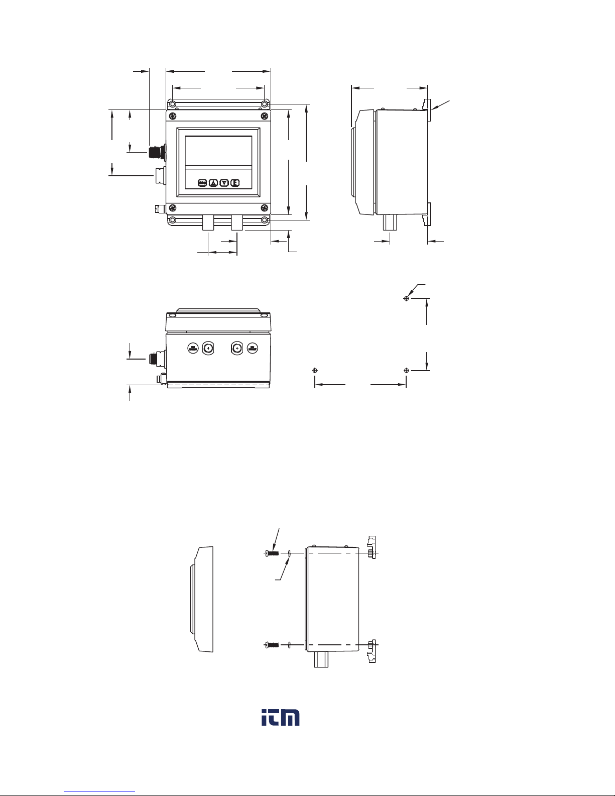
BRACKETS
ARE OPTIONAL
4X ø3/16 [4.76] CLEARANCE
HOLES FOR MOUNTING
3-17/64
[83]
MOUNTING HOLE
PATTERN
4-1/8
[105]
1-5/32
[29.59]
#8-36 SLOTTED MACHINE SCREW
#8 LOCK
WASHER
BRACKET ASSEMBLY
1-45/64
[43.18]
2
-31/32
[
75.39]
4-23/32
[120]
4
-9/64
[
105.17]
1
DIMENSIONS
OPTIONAL A-438 BRACKET
MOUNTING DIAGRAM
Shown with Optional A-438 Mounting Bracket
www. .com
information@itm.com1.800.561.8187
Page 3

2
SPECIFICATIONS
Service: Air and non-corrosive gases.
Wetted Materials: Ranges 5˝ and greater: glass, PVC, silicon, alumina ceramic, epoxy,
RTV, gold, aluminum, stainless steel and nickel; Ranges 1˝ and lower: stainless steel,
silicone, gold and ceramic.
Housing Materials: Aluminum, glass.
Accuracy: ±0.5% at 77°F (25°C) including hysteresis and repeatability (after 1 hour
warm-up).
Stability: < ±1% per year.
Pressure Limits: Ranges ≤ 2.5 in. w.c. = 2 psi;
5˝: 5 psi; 10˝: 5 psi; 25˝: 5 psi; 50˝: 5 psi; 100˝: 9 psi.
Temperature Limits: 32 to 161.6°F (0 to 72°C).
Compensated Temperature Limits: 32 to 140°F (0 to 60°C).
Thermal Effects: 0.020%/°F (0.036/°C) from 77°F (25°C).
Power Requirements: 10-35 VDC.
Output Signal: 4-20 mA DC.
Zero & Span Adjustments: Accessible via menus.
Response Time: 250 ms (dampening set to 1).
Display: 4 digit LCD 0.6˝ height.
Electrical Connections: M12 4 PIN Connector.
Process Connections: 1/8 female NPT.
Enclosure Rating: Designed to meet NEMA 4x (IP66).
Mounting Orientation: Mount unit in horizontal plane.
Size: 4.73˝ x 4.73˝ x 3.43˝ (120 mm x 120 mm x 87.1 mm).
Weight: 2 lb 10 oz (1.19 kg).
Agency Approvals: FM Approved: IS / I, II, III / 1 / ABCDEFG / T4 Ta = 0°C to 72° - 19-
443480-50; ENTITY; TYPE 4X (US AND CANADA) I / 0 AEx ia / IIC / T4 Ta = 0°C to 72°
- 19-443480-50; ENTITY; TYPE 4X (US) I / 0 / Ex ia / IIC / T4 Ta = 0°C to 72° - 19443480-50; ENTITY; TYPE 4X (CANADA) CE. CENELEC EN 61326/55024: 2003; IEC
61000-4-2/3/4/6: 2001/2006/2004/2005; CENELEC EN 55011: 2006; 2004/108/EC EMC
Directive.
Intrinsic Safety Information
Entity Parameters
Ui = 28VDC
Ii = 93mA
Ci = 22 nF
Li = 400 uH
Pi = 651mW
Notes:
1. Remove power from the instrument before carrying out any servicing.
2. Use only FM approved Associated Apparatus.
3. The earth terminal on the housing must be wired to a local earth ground in the
hazardous area.
4. Refer to control drawing 19-443480-50, Page 15, for installation requirements.
www. .com
information@itm.com1.800.561.8187
Page 4
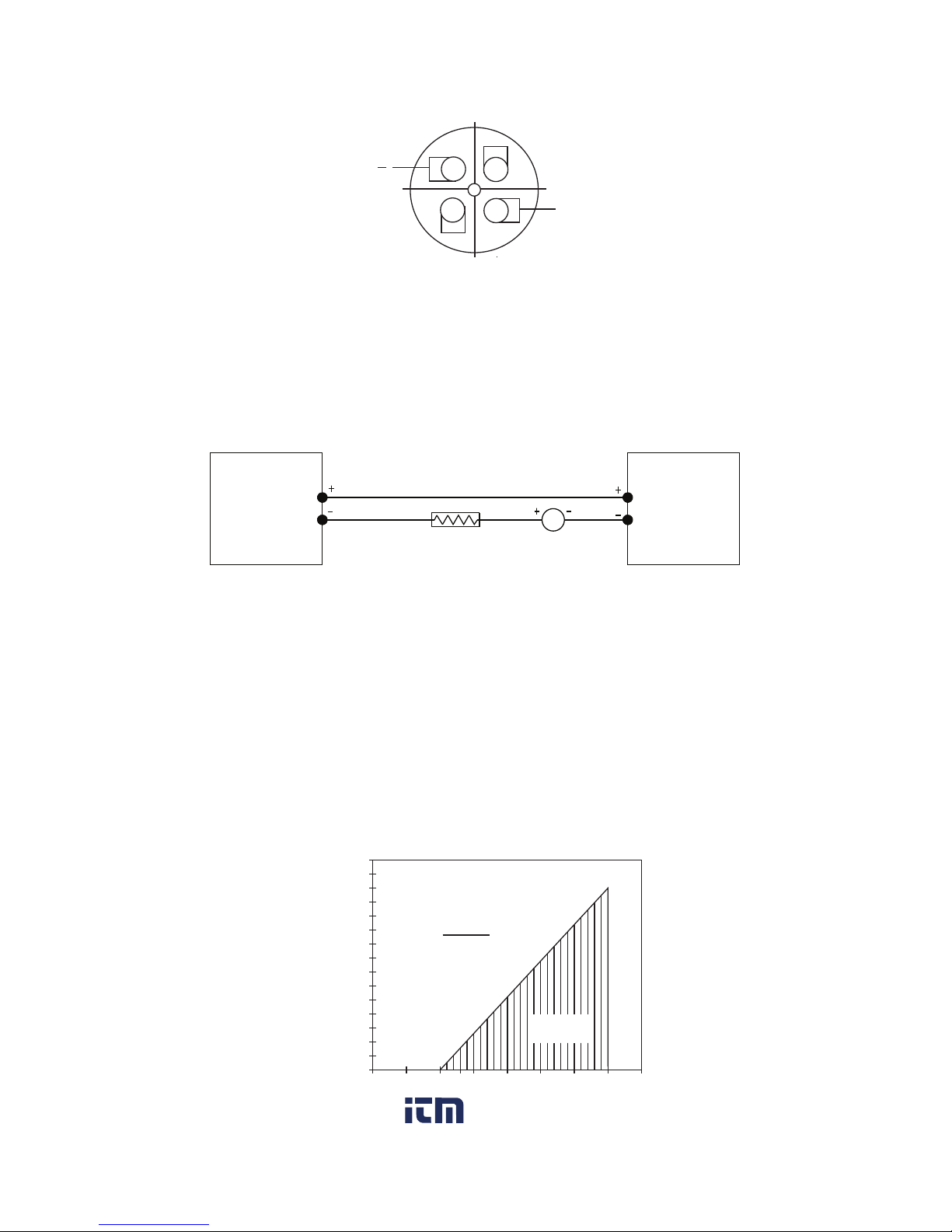
MAXIMUM VAL UE ( 1250Ω)
OPERATING
REGION
R L MAX=
Vps -10. 0
20mA DC
VDC
0
5101315
20
25
30
35
T
O
TAL
RECEI
VER
RESI
STANCE
(Ω)
1500
1400
1300
1200
1100
1000
900
800
700
600
500
400
300
200
100
50
40
ISDP
TRANSMITTER
RECEIVER
POWER
SUPPLY
10-35 VDC
mA
3
-------2-Wire Operation- An external power supply delivering 10 - 35 VDC with minimum
current capability of 40 mA DC (per transmitter) must be used to power the control loop.
See Fig. C for connection of the power supply, transmitter, and receiver. The range of the
appropriate receiver load resistance (RL) for the DC power supply voltage available is
expressed by the formula and graph in Fig. D.
POWER SUPPLY VOLTAGE - VDC (2-WIRE CONNECTION)
A-231 M-12 Cable Colors
PIN 1 is Brown (positive)
PIN 3 is Blue (negative)
Use Model A-231 shielded cable with 4 pin Female M-12 connection.
M-12 Connector
2-WIRE CONNECTION
Fig. C
3
2
1
4
+
Fig. D
www. .com
information@itm.com1.800.561.8187
Page 5
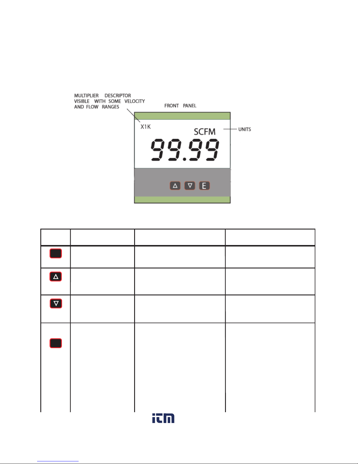
4
MENUMENU
EE
HOME POSITION
FUNCTION
Allows access to
the menus
Displays full scale
range of unit
MAIN MENU
FUNCTION
Return to home
position
Sequences through menus
Sequences through menus
Enter into SUB MENU
SUB MENU
FUNCTION
Return to previous menu
Increments a value
Decrements a value
Changes a value or
setting. Press ENTER and
display will blink. Adjust
with UP or DOWN arrows.
Press ENTER to store.
Display will stop blinking.
Peak/Valley SUB MENU
resets display to present
value.
MENU
UP
ARROW
DOWN
ARROW
ENTER
KEY FUNCTIONS
INSTALLATION
Mount the instrument in a location that will not be subject to excessive temperature, shock
or vibration.
Pressure Connections
Use 1/8˝ male NPT fittings. When tightening fittings, grasp the brass fitting on the ISDP
with a 1/2˝ wrench to prevent the fitting on the ISDP from turning.
www. .com
information@itm.com1.800.561.8187
Page 6

5
MENU MAPMENU MAP
CONTINUED
CONTINUED
SETTINGSSETTINGS
MAIN MENUS SUB MENUS
MENUS
UNAVAILABLE
FOR
BI-DIRECTIONAL
RANGES AND
RANGES ABOVE
25 IN. W.C.
EE
MENUMENU
MENU MAP
MAIN MENUS
SUB MENUS
SETTINGS
CONTINUED
MENUS
UNAVAILABLE
FOR
BI-DIRECTIONAL
RANGES AND
RANGES ABOVE
25 IN. W.C.
www. .com
information@itm.com1.800.561.8187
Page 7

6
CONTINUEDCONTINUED
EE
MENUMENU
CONTINUED
www. .com
information@itm.com1.800.561.8187
Page 8

MAIN MENUS SUB MENUS
SETTINGS
7
Menus present only
in pressure operation
EE
MENUMENU
MAIN MENUS
SUB MENUS
SETTINGS
www. .com
information@itm.com1.800.561.8187
Page 9

8
Main Menu Selections (Upper Right Display Reads
MENU
)
SECr
Security - Lock out access to menus and settings.
OPEr
Operation - Selection of Pressure, Velocity or Flow and corresponding
engineering units.
diS
Display - Monitor and adjust display related settings: Peak, Valley, display
resolution, % output and dampening.
AdU
Advanced functions - Modify advanced function parameters, transmitter
output scaling, and calibration.
Model Chart
Model
ISDP-002
ISDP-004
ISDP-005
ISDP-006
ISDP-007
IDSP-008
ISDP-009
ISDP-010
ISDP-011
ISDP-012
ISDP-013
ISDP-014
ISDP-015
ISDP-016
ISDP-017
Range
0-0.25˝
0-1˝ WC
0-2.5˝ WC
0-5˝ WC
0-10˝ WC
0-25˝ WC
0-50˝ WC
0-100˝ WC
-0.1/+0.1˝ WC
-0.25/+0.25˝ WC
-0.5/+0.5˝ WC
-1.0/+1.0˝ WC
-2.5/+2.5˝ WC
-5.0/+5.0˝ WC
-10/+10˝ WC
www. .com
information@itm.com1.800.561.8187
Page 10

9
MAIN MENUS and SUB MENUS
SECr
(Security) MAIN MENU
SECr
is the only SUB MENU in the security MENU. When the security SUB MENU
is selected, the present security level is displayed in the upper right hand display. To
change the security level, adjust the number displayed to the number shown in the
following table for the desired security level.
The password values shown in the table cannot be altered, so retain a copy
of these pages for future reference.
OPEr
(Operation) MAIN MENU
The
OPEr
MENU selects the measurement type of the instrument.
The SUB MENUS are:
PrES
- Pressure
KFAC
- K Factor
XDIM
- X Dimension
UEL
- Velocity
ArEA
- Area
YDIM
- Y Dimension
FLO
- Flow
DIA
- Diameter
If the instrument is set for Velocity, the
OPEr
MENU will have an additional
KFAC
SUB
MENU. If the instrument is set for Flow, the
OPEr
MENU will have additional
KFAC
and
ArEA
SUB MENUS. These will be discussed under Velocity and Flow. When scrolling
through the
OPEr
SUB MENUS, the measurement type the unit is currently set for will
show the units in the upper right display. The other measurement types will have a blank
upper right display.
Security Level
Displayed
1
2
Access
All menus access
All settings locked
Password Value
to Enter
10
70
Units visible, so unit
is presently set to
measure pressure
is presently set to
measure pressure
Units not visibleUnits not visible Units not visibleUnits not visible
www. .com
information@itm.com1.800.561.8187
Page 11

10
PrES
(Pressure) SUB MENU
For pressure measurement, the following units are available:
Table 1 Pressure Range vs. Available Units
INWC
.1000
.2500
.5000
1.000
2.500
5.000
10.00
25.00
50.00
100.0
FTWC
.2083
.4167
.8333
2.083
4.167
8.333
MMWC
2.540
6.350
12.70
25.40
63.50
127.0
254.0
635.0
1270
2540
CMWC
.2540
.6350
1.270
2.540
6.350
12.70
25.40
63.50
127.0
254.0
PSI
.1806
.3613
.9032
1.806
3.613
INHG
.1839
.3678
.7356
1.839
3.678
7.356
MMHG
.1868
.4671
.9342
1.868
4.671
9.342
18.68
46.71
93.42
186.8
MBAR
.2491
.6227
1.245
2.491
6.227
12.45
24.91
62.27
124.5
249.1
PA
24.91
62.27
124.5
249.1
622.7
1245
2491
6227
KPA
.1245
.2491
.6227
1.245
2.491
6.227
12.45
24.91
HPA
.2491
.6227
1.245
2.491
6.227
12.45
24.91
62.27
124.5
249.1
OZIN
.1445
.2890
.5780
1.445
2.890
5.780
14.45
28.90
57.80
UEL
(Velocity) SUB MENU
For velocity measurement, the following units are available:
SFPM
- Standard feet per minute
M/S
- Meters per second
Table 2 Available Velocity Ranges
NOTE: Air velocity and flow readings are based upon standard dry air conditions with an
ambient temperature of 70°F and a barometric pressure of 29.92 INHG.
INPUT RANGE INWC
0 - 0.1
0 - 0.25
0 - 0.5
0 - 1
0 - 2.5
0 - 5
0 - 10
0 - 25
SFPM RANGE
0 - 1266
0 - 2002
0 - 2832
0 - 4004
0 - 6332
0 - 8954
0 - 12.66 x IK
0 - 20.02 x IK
M/S RANGE
0 - 6.431
0 - 10.17
0 - 14.39
0 - 20.35
0 - 32.17
0 - 45.48
0 - 64.33
0 - 101.7
INWC
- Inches of water column
FTWC
- Feet of water column
MMWC
- Millimeters of water column
CMWC
- Centimeters of water column
PSI
- Pounds per square inch
INHG
- Inches of mercury
MMHG
- Millimeters of mercury
MBAR
- Millibar
PA
- Pascal
KPA
- Kilopascals
HPA
- Hectopascals
OZIN
- Ounce inches
NOTE:
OVFL
(over flow) or
UnFL
(under flow) will appear when the ranges have been
exceeded above or below full scale by 2%.
www. .com
information@itm.com1.800.561.8187
Page 12

F
LO
(Flow) SUB MENU
For flow measurements the following units are available:
SCFM
- Standard cubic feet per minute
M^3H
- Cubic meters per hour
FLO r
(Flow Range) SUB MENU
LO
- 99.99 x 1K flow range
HI
- 999.9 x 1K flow range
Tables 3 -6 show the flow ranges available, and the maximum duct size that can be set for
each input range.
Table 3
FLOr = LO
Maximum Duct Size (English)
RANGE
IN WC
0.1
0.25
0.5
1
2.5
5
10
25
SCFM
RANGE
99.99 x 1K
99.99 x 1K
99.99 x 1K
99.99 x 1K
99.99 x 1K
99.99 x 1K
99.99 x 1K
99.99 x 1K
MAX. DUCT
SIZE, SQ. FT.
78.9
49.9
35.3
24.9
15.7
11.1
7.8
4.9
Table 4
FLOr = HI
Maximum Duct Size (English)
RANGE
IN WC
0.1
0.25
0.5
1
2.5
5
10
25
SCFM
RANGE
999.9 x 1K
999.9 x 1K
999.9 x 1K
999.9 x 1K
999.9 x 1K
999.9 x 1K
999.9 x 1K
999.9 x 1K
MAX. DUCT
SIZE, SQ. FT.
789.8
499.5
353.1
249.7
157.9
111.7
78.9
49.9
Table 5
FLOr = LO
Maximum Duct Size (Metric)
RANGE
IN WC
0.1
0.25
0.5
1
2.5
5
10
25
Mˆ3/Hr
RANGE
99.99 x 1K
99.99 x 1K
99.99 x 1K
99.99 x 1K
99.99 x 1K
99.99 x 1K
99.99 x 1K
99.99 x 1K
MAX. DUCT
SIZE Mˆ2
4.32
2.73
1.93
1.37
0.86
0.61
0.43
0.27
Table 6
FLOr = HI
Maximum Duct Size (Metric)
RANGE
IN WC
0.1
0.25
0.5
1
2.5
5
10
25
Mˆ3/Hr
Range
999.9 x 1K
999.9 x 1K
999.9 x 1K
999.9 x 1K
999.9 x 1K
999.9 x 1K
999.9 x 1K
999.9 x 1K
MAX. DUCT
SIZE, Mˆ2
43.19
27.31
19.3
13.64
8.63
6.10
4.31
2.73
KFAC
SUB MENU
KFAC
K Factor - becomes accessible if the instrument is set for Velocity or Flow. When
the Digihelic
®
II Controller is used with a Pitot tube, the manufacturer may specify a K
Factor. The adjustment range is 0.01 to 2.00. The factory setting is 1.
11
www. .com
information@itm.com1.800.561.8187
Page 13

12
A
rEA
,
D
IA
,
X
DIM
and
Y
DIM
SUB MENUS
These SUB MENUS become accessible if the instrument is set for flow. When measuring
flow, the area of the duct must be specified. Tables 3 and 4 show the input range vs
maximum flow and duct size. For a rectangular duct the maximum size is specified in
square feet or meters. For a circular duct the maximum size is specified as the diameter.
X, Y and circular dimensions are entered in feet with 0.01 foot resolution for
FLOr = LO
and
0.1 foot resolution for
FLOr = HI
, or entered in millimeters with 1 millimeter resolution.
ArEA
- Area, select
CIR
for a circular duct or
RECT
for a rectangular duct. If a
circular duct is selected, the
DIA
SUB MENU will be activated. If a rectangular duct is
selected, the
XDIM
and
YDIM
SUB MENUS will be activated.
DIA
- Diameter, enter the diameter of a duct
XDIM
- Enter the “X” dimension of a duct
YDIM
- Enter the “Y” dimension of a duct
d.S
(Display) MAIN MENU
PEAK
- Peak value
rESO
- Resolution
VALy
- Valley value
Pd.S
- Process display
ZERO
- Zero
DAMP
- Dampening level
PEAK
(Peak) SUB MENU
The Peak feature stores the highest pressure reading the instrument has measured
since the last reset or power up. At power up
PEAK
is reset to the present
pressure reading. To manually reset the
PEAK
value, press the ENTER key while in
the
PEAK
SUB MENU.
VALy
(Valley) SUB MENU
The valley feature stores the lowest pressure reading the instrument has measured
since the last reset or power up. At power up
VALy
is reset to the present
pressure reading. To manually reset the
VALy
value, press the ENTER key while in
the
VALy
SUB MENU.
Y
X
www. .com
information@itm.com1.800.561.8187
Page 14

13
r
ESO
(Resolution) SUB MENU
The Series ISDP Controller is capable of displaying four digits of resolution.
However, at very low pressures the instability of the pressure may cause
fluctuations in the least significant digit causing the least significant digit to be of
little value.
Three digit resolution (
3DIG
) can only be active when there is at least one digit to
the right of a decimal.
3DIG
- Set display for 3 digit resolution
4DIG
- Set display for 4 digit resolution
Pd.S
(Process Display) SUB MENU
STD
- Display reads pressure, velocity, or flow values
PCT
- Display reads % of full scale value
When the display is reading percent,
PCT
is displayed in the upper right of the
display. The percent display is only available in pressure operation.
DAMP
(Dampening) SUB MENU
Adjust from 1-16
Dampening stabilizes the display from instabilities due to things such as vibration
and excessive pressure fluctuations. The dampening setting adjusts the amount of
readings that are averaged for each display update. Adjust the dampening value
until the display reads a stable value for the application.
AdU
(Advanced) MAIN MENU
POL
- Process output low
POH
- Process output high
ZERO
- Zero calibration
SPAN
- Span calibration
POL
and
POH
(Process Output Low and High) SUB MENUS
This feature is used in pressure operation only.
Process output low and high are used to scale the 4-20 mA output. Set
POL
to the
desired display reading for 4mA output, and set
POH
to the desired display
reading for 20 mA output.
POH
must be higher than
POL. POL
may be adjusted 2%
BELOW minimum scale up to
POH. POH
may be adjusted from
POL
to 2% ABOVE
maximum scale.
www. .com
information@itm.com1.800.561.8187
Page 15

Z
ERO
and
S
PAN
(Calibration of Zero and Span) SUB MENUS
The lower display reads
CAL
in this mode.
ZERO
Calibration
NOTE: For accurate calibration, DO NOT apply any pressure when performing
this function.
With the display reading
ZERO
, press the ENTER key. The upper display will blink.
Press ENTER again to complete the zeroing of the instrument or press the
MENU
key to cancel.
SPAN
Calibration
With the display set to
SPAN
, apply full scale pressure to the unit. Press the ENTER
key. The upper display will blink. Press ENTER again to complete the calibration or
press the
MENU
key to cancel.
Maintenance
Upon final installation of the Series ISDP intrinsically Safe Differential Pressure
Transmitter, no routine maintenance is required. The Series ISDP is not field serviceable
and should not be returned if repair is needed (field repair should not be attempted and
may void warranty). Be sure to include a brief description of the problem plus any
relevant application notes. Contact customer service to receive a return goods
authorization number before shipping.
14
www. .com
information@itm.com1.800.561.8187
Page 16

DWYER INSTRUMENTS, INC.
Phone: 219/879-8000 www.dwyer-inst.com
P.O. BOX 373 • MICHIGAN CITY, IN 46360, U.S.A. Fax: 219/872-9057 e-mail: info@dwyermail.com
©Copyright 2014 Dwyer Instruments, Inc.
Printed in U.S.A. 12/14
FR# 19-443480-00 Rev. 3
ACAD2002
parties for examination without the written consent of said corporation.
to be communicated, disclosed, reproduced or used except as previously authorized in writing by such corporation and must not be submitted to outside
NOTICE: This drawing and the principles and elements of design embodied therein are the exclusive property of DWYER INSTRUMENTS, INC. and are not
F
R
.
N
O
.
ALL ANGLES ±
ALL DECIMAL DIMENSIONS ±
STANDARD TOLERANCES UNLESS NOTED:
NO. BY/DATECHANGES
APPD
CHKD
DWN BY
NAMEDATE
MATERIAL
FINISH
MICHIGAN CITY, INDIANA 46360 U.S.A.
3
CD = CRITICAL DIMENSION
19-443480-50
19-443480-50
19-443480-50
01-02-08
KAS
CAR
LRR
FM CONTROL DRAWING
ISDP
SCALE 1:1
1
CLASS II AND CLASS III RATINGS
REMOVED ITEM 6 PER ECR #22759
KAS
01-15-08
2
ADDED CLASS II AND III RATINGS PER ECR #23754
AJB
8-6-08
3
REVISED NOTE 3 TO ADD CANADIAN ELECTRICAL CODE PER ECR #25003
KAS
05-05-09
4
UPDATE TO ZONES PER DWK 06-11-14, ECR 35481
PFA
6-23-14
1°
.005
CATALOG NUMBERS
ISDP-001 THROUGH ISDP-017
HAZARDOUS (CLASSIFIED) LOCATION
INTRINSICALLY SAFE FOR:
CLASS I DIV. 1 GROUPS A, B, C, D
T4 Ta 0°C TO 72°C TYPE 4X
OR
1. THE INTRINSIC SAFETY ENTITY CONCEPT ALLOWS THE INTERCONNECTION OF TWO FM APPROVED INTRINSICALLY SAFE DEVICES
WITH ENTITY PARAMETERS NOT SPECIFICALLY EXAMINED IN COMBINATION AS A SYSTEM WHEN:
Voc OR Uo OR Vt < Vmax, Isc OR It < Imax< Ca OR Co > Ci + Ccable, La OR Lo > Li + Lcable, Po < Pi
2. EQUIPMENT CONNECTED TO THE ASSOCIATED APPARATUS MUST NOT USE OR GENERATE MORE THAN 250 Vrms OR VDC.
3. DIVISION 1 HAZARDOUS (CLASSIFIED) LOCATIONS INSTALLATIONS MUST BE IN ACCORDANCE WITH THE NATIONAL ELECTRICAL CODE NFPA 70, ARTICLE 504;
4. NO REVISIONS WITHOUT PRIOR APPROVAL FROM FM RESEARCH.
5. THE ASSOCIATED APPARATUS MANUFACTURERS INSTALLATION INSTRUCTIONS MUST BE FOLLOWED WHEN INSTALLING THIS EQUIPMENT.
ISDP SERIES TRANSMITTER
Vmax = 28VDC
Imax = 93mA
Ci = 22nF
Li = 400uH
Pi = 651mW
+
-
+
-
FM APPROVED
ASSOCIATED APPARATUS
OPTIONAL SHIELD
NON-HAZARDOUS LOCATION
I.S. SAFETY
GROUND
CLASS II DIV. 1 GROUPS E, F, G
CLASS III DIV. I
ZONE 0 HAZARDOUS LOCATIONS MUST BE IN ACCORDANCE WITH THE NATIONAL ELECTRICAL CODE NFPA 70, ARTICLE 505; IN US. INSTALLATIONS MUST BE
CLASS I, ZONE 0, GROUPS IIC
T4 Ta 0°C TO 72°C TYPE 4X
IN ACCORDANCE WITH THE CANADIAN ELECTRICAL CODE CSA C22.1, PART 1, APPENDIX F; IN CANADA. ALL INSTALLATIONS MUST BE IN ACCORDANCE
WITH ISA RP-12.6.
6. WARNING - ENCLOSURE PARTS ARE CONSTRUCTED OF ALUMINUM. ENCLOSURE MUST BE PROTECTED FROM MECHANICAL FRICTION AND IMPACT WITH
IRON/STEEL TO PREVENT IGNITION CAPABLE SPARKS.
7. SUBSTITUTION OF PARTS MAY IMPAIR INTRINSIC SAFETY. RETURN TO MANUFACTURER FOR ANY REPAIRS.
8. ADDITIONAL SUFFIXES AT (ALUMINUM TAG), COO (CERTIFICATE OF ORGIN), FC (FACTORY CALIBRATION CERTIFICATE), NIST (NIST TRACEABLE)
www. .com
information@itm.com1.800.561.8187
 Loading...