

Page 1

Series IEF Insertion Electromagnetic Flow Transmitter
5-53/64 [148.0]
61/64
[24.2]
22-1/64
7-3/32 [180.2]
®
Specications - Installation Instructions
For full Installation and Operating Instructions refer to Bulletin F-IEF-F at
http://www.dwyer-inst.com/Product//SeriesIEF#literature
5-53/64
[148.0]
[559.2]
-LCD option shown
Shown with A-IEF-VLV-BR
accessory valve
Bulletin F-IEF-QS
4-51/64
[121.8]
The Series IEF Insertion Electromagnetic Flow Transmitter is an adjustable
insertion owmeter featuring electromagnetic technology that accurately and reliably
measures uid velocity in addition to providing several continuous signal outputs.
This series is specically designed to offer superior performance paired with simple
installation and use. One unit is adjustable to t pipe sizes from 4 to 36˝ (101.6 to
914.4 mm), and offers several output options including selectable BACnet MS/TP or
®
RTU communications protocol over 2-wire RS-485 in addition to the standard
Modbus
analog, frequency and alarm outputs.
FEATURES/BENEFITS
• Field congurable, integral or remote setup displays (-LCD option or accessory
A-IEF-DSP) allow for ultimate exibility by accommodating a variety of application
congurations with one model through multiple display congurations i.e. pipe
size, pipe material, liquid type, analog output, pulse/frequency output, alarm outputs,
communication outputs, damping, and calibration factor.
• High performance accuracy is maintained through temperature, density or viscosity.
• Setup Wizard and installation tool are simple to use allowing for quick and precise
installation.
• Accessory setup kit A-IEF-KIT ensures exact installation application depth with
included thickness gage and measuring tape.
• Long Life Cycle and minimal maintenance requirements with no moving parts to
wear or break and electrodes that discourage fouling.
• Isolation valve accessory options allow for installation in operational systems via
hot-tap kit or easy removal without system downtime.
• NIST calibration certicate included standard for Carbon Steel Schedule 40 pipes
sized 4˝ (100 mm), 6˝ (150 mm), 8˝ (200 mm), and 10˝ (250 mm) with high accuracy
option.
APPLICATIONS
• Boiler feed water
• Chilled water
• Open and closed loop condenser water
• Irrigation system
• Municipal water distribution
• Process and coolant ow
• Ground water remediation
• Chemical processing
• Pump protection
• Wastewater
• Mining
SPECIFICATIONS
Service: Compatible clean or dirty non coating, conductive liquids.
Range: 0 to 20 ft/s (0 to 6 m/s).
Wetted Materials: Body shaft/tting: 316SS; Electrodes: 316SS; Electrode cap:
Polymer/Polystyrene; O-ring: Silicone.
Accuracy: IEF-HX-X: ±0.5% of reading at calibrated velocity; ±1% of reading from
2 to 20 ft/s (0.6 to 6 m/s) ±0.02 ft/s (±0.006 m/s) at < 2 ft/s (0.6 m/s). IEF-SX-X:
±1% FS.
Temperature Limits: Ambient: -20 to 160°F (-29 to 71°C); Process: 15 to 250°F (-9
to 121°C); Storage: -40 to 185°F (-40 to 85°C).
Process Connection: 1˝ NPT or BSPT with accessory full port ball valve options.
Pressure Limits: 400 psi (27.6 bar) @ 100º F (37.8°C).
Pressure Drop: < 0.1 psi at 12 ft/s in 4˝ (101.6 mm) and larger pipe.
Outputs:
(1) Analog: 4 to 20 mA, 0 to 5 V, 0 to 10 V or 2 to 10 V (display selectable);
(1) Pulse/Frequency: 0 to 15 V peak pulse, 0 to 500 Hz or scalable pulse output
(display selectable);
(2) Alarms: (1) Empty pipe detection or minimum/maximum velocity, (display
selectable); (1) Reverse ow output indication.
Power Requirements: 12 to 42.4 VDC, .25 A @ 24 VDC; 12 to 36 VAC.
Electrical Connection: Removable terminal blocks, model selectable 1/2˝ female
NPT conduit connection, PG 16 gland or PG 16 gland with (2) 10 ft (3 m) 9
conductor 22 AWG plenum rated cables, accessory cable lengths up to 200 ft (61
m) optional.
Display (-LCD option): 2˝ ( 5.08 cm) x 2˝ (5.08 cm) graphic LCD with backlight.
Conductivity: >20 microsiemens.
Enclosure Material: Powder coated die cast aluminum.
Enclosure Ratings: NEMA 6P (IP68) (Non display models); NEMA 4X (IP66)
(-LCD option).
Agency Approvals: BTL, CE, NSF/ANSI 61 and 372 pending.
COMMUNICATIONS (-COM OPTION)
Type: BACnet MS/TP or Modbus
display selectable).
Supported Baud Rates: 9600, 19200, 38400, 57600, 76800, or 115200 bps
(display selectable).
Device Load: 1/8 unit load.
®
RTU communication protocol (default disabled,
DWYER INSTRUMENTS, INC.
P.O. BOX 373 • MICHIGAN CITY, INDIANA 46360, U.S.A.
ADDITIONAL SPECIFICATIONS
Applicable Pipe Material: Most popular plastic and metal pipes; i.e. Carbon steel,
SS, copper, UPVC/PVDF, galvanized steel, mild steel, and brass.
Applicable Pipe Size: IEF-HX-X: 4 to 10˝ (101 to 254 mm); IEF-SX-X: 4 to 36˝
(101 to 914 mm).
Diameter Length Requirements: >10 upstream, >5 downstream.
Glycol: 0 to 100% display selectable.
Modbus® is a registered trademark of Schneider Automation, Inc.
Phone: 219/879-8000
Fax: 219/872-9057
www.dwyer-inst.com
e-mail: info@dwyermail.com
Page 2
MODEL CHART
THUMBSCREW
BODY
RULER
Example IEF -H N -CND -LCD IEF-HN-CND-LCD
Series IEF Insertion electromagnetic ow transmitter
Accuracy H
Process
Connection
Electrical
Housing
Connector
S
N
B
CND
PG
10
High accuracy; 1% of reading
Standard accuracy; 1% FS
1˝ NPT
1˝ BSPT
1/2˝ female NPT
PG 16 gland
PG 16 gland with (2) 10´ (3 m) plenum
rated cables
Options LCD
Integral LCD
BACnet or Modbus
COM
®
communication
protocol (display selectable)
Multiple point NIST traceable calibration
NIST
certicate
Factory calibration certicate for 0.5% of
FC
reading at single point
CC
Custom congured for specic installation
ACCESSORIES
Model Description
A-IEF-KIT
Setup kit (includes setup display, thickness gage and measuring
tape)
A-IEF-DSP
A-IEF-CBL-50
A-IEF-VLV-BR
A-IEF-VLV-SS
A-IEF-INGD
A-IEF-PA
Setup display
Plenum rated cable 50 ft (15.2 m)
1-1/4˝ full port isolation valve brass
1-1/4˝ full port isolation valve 316SS
Installation alignment kit
AC wall adapter
INCLUDED WITH THE FLOWMETER
Carefully unpack the shipping container of your new Series IEF Insertion
Electromagnetic Flow Transmitter and remove the following items:
• (1) Series IEF Insertion Electromagnetic Flow Transmitter
• (1) A-IEF-INGD Installation Alignment Kit:
(1) Alignment Scale
(2) Alignment Rods
(2) Thumbscrews
• (1) 3 mm Allen Wrench (not shown)
(2 PLACES)
Thumbscrew (2)
ROD
Alignment scale (2)
Rod (2)
Series IEF
Figure 1
Figure 2
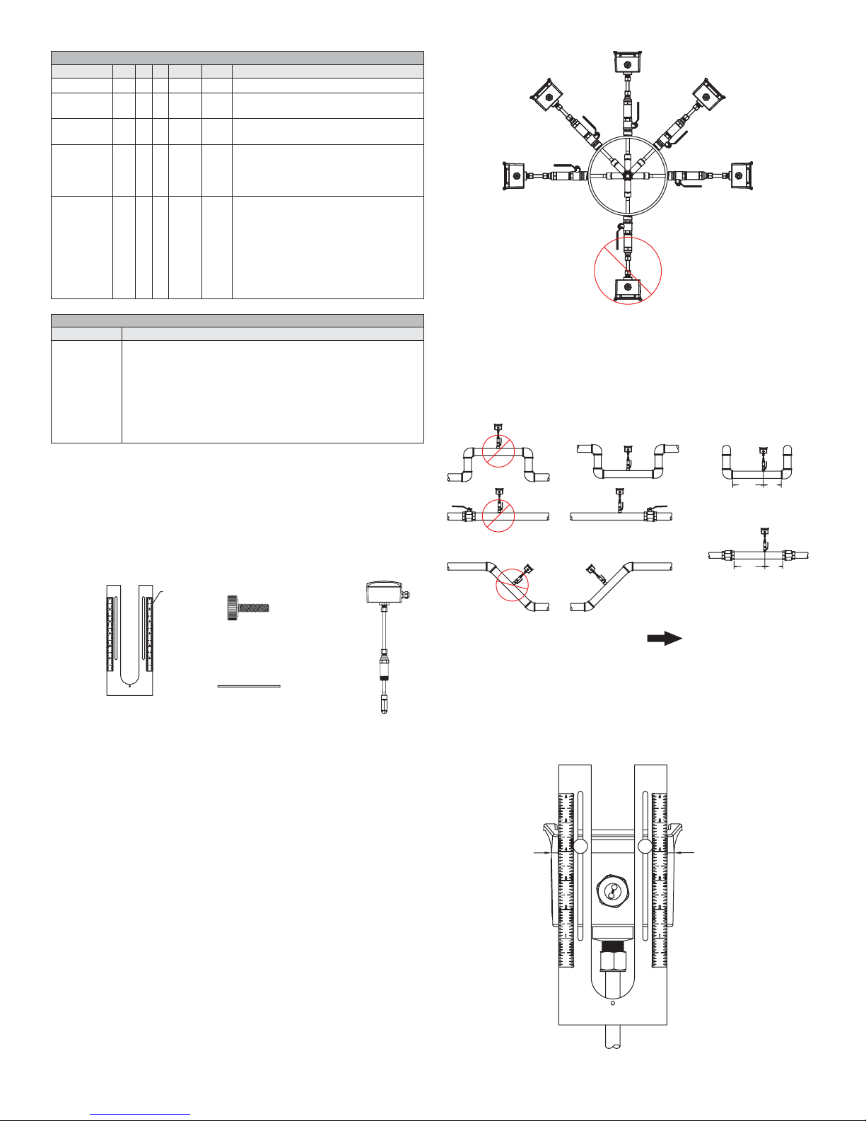
2. Select a location that will minimize ow distortion with adequate upstream and
downstream pipe diameters as displayed. Ideal installation will have a minimum
of 10 pipe diameters upstream relative to the instrument and a minimum distance
of 5 pipe diameters downstream.
5x
20x
20x
5x
FLOW DIRECTION
Figure 3
INSTALLATION
1. To prepare the meter for installation, mount the provided alignment scale to the
side of the meter with the two provided thumbscrews. The thumbscrews are to be
inserted through the alignment scale slots and into the holes in the side of the lid
as shown in Figure 4, nger tighten only. Be sure to orient the alignment scale as
shown in gure below. Actual scale setting determined in next step.
RECOMMENDED TOOLS
• (2) 12˝ (300 mm) adjustable wrenches
• (1) 12˝ (300 mm) pipe wrench
SETUP
Selecting Installation Location
1. Although the unit may be installed in any orientation, the ideal mounting position
is on the side of the pipe (2 o’clock or 10 o’clock position) as this generally
minimizes possible air or sediment interference with the Series IEF.
Note: When installing a unit with an integral display select an installation
location that allows for clear viewing of the display and proper earth ground.
Insert the IEF in a pipe via a threaded Tee, Saddle, or welded integrally
reinforced branch connection outlet tting.
If a Hot-Tap option is required, use a 1-1/4˝ valve kit with proper mounting
hardware available in Model A-IEF-VLV-BR or A-IEF-VLV-SS. A 1˝ (25.4 mm)
hole in the pipe is required for proper installation.
Figure 4
USE LID TO
ENCLOSURE
GAP AS
INDICATOR LINE
Page 3

For Custom Congured Models (-CC Option)
KEYLINE
TURE
1
8
2. Locate the conguration tag attached to the Series IEF to identify the value of
the alignment scale setting. Position the alignment scale such that the scale
setting is lined-up with the seam of the enclosure as shown in Figure 4. Minor
scale marks are in 1/20ths Securely tighten the thumbscrews.
3. Refer to Preparing the Unit for Installation section.
For Field Congurable Models
2. For eld conguration a display is required (-LCD option or accessory A-IEF DSP) and needs to be powered via normal eld wiring or with the AC wall adapter
accessory A-IEF-PA ( A-IEF-DSP and A-IEF-PA are also available in the
accessory setup kit A-IEF-KIT).
3. When using the AC wall adapter and the cable is supplied, connect the red
(positive +) and black (common -) wires of the cable bundle marked “A” to the
open terminals of the AC wall adapter. This will provide temporary power to the
meter to complete the installation set up.
4. For eld wiring refer to the wiring chart tag attached to the Series IEF to identify
the terminal block pins for positive (+) and common (-) connection.
5. Unscrew the four captured cover screws using the supplied 3 mm Allen wrench
to remove and set aside enclosure cover.
6. Insert one connector of the ribbon cable supplied in the setup kit into the
connector labeled “Display” in the middle of the unit. Be sure to orient the keying
feature/tab. See Figure 5 below:
FEA
Preparing the Unit for installation (Refer to Figure 7)
1. Apply appropriate sealant to the process collet (5) threads such as application
suitable sealant tape or paste.
2. Install the process collet (5) in valve (6) then tighten by hand.
3. Tighten the process collet (5) with a wrench using the hex geometry until snug.
NOTICE
4. Slowly open the valve handle (7) checking for leaks.
5. If leaks occur around threaded connections, close the valve and tighten those
connections.
Use two wrenches, one to hold the valve and another wrench to
turn the process collet.
2
4
5
6
3
7
Figure 5
7. Plug the other end of the cable into the bottom of the supplied portable display
being sure to orient the keying feature/tab as shown:
KEYLINE
FEATURE
Figure 6
8. Apply power to the unit and the display will turn-on automatically. Follow the on
screen directions for entering the necessary parameters to setup the unit and
obtain the alignment scale setting value.
NOTICE
DSP, thickness gage UTG and measuring tape A-IEF-MSTP used to obtain these
measurements. When the precise pipe measurement information is known select
Option 2 High Performance setup in the Install Kit option of the display selection
When using measuring tape A-IEF-MSTP to measure pipe
NOTICE
of the pipe without insulation.
Precise pipe measurements are required for high performance
installation. The A-IEF-KIT includes setup display A-IEF-
circumference use the 100ths side to measure the circumference
9
Figure 7
Do not adjust housing compression nut at top of probe shaft (3).
NOTICE
1. Enclosure
2. Cable Nut
3. Probe Shaft
4. Compression Fitting
5. Process Collet
6. Valve (optional)
7. Valve Handle (optional)
8. Pipe
9. Sensor Probe
Page 4

Sensor Alignment
FLOW
OOL
PIPE ALIGNMENT ROD MUST
g
A depth and ow alignment installation tool is provided to ensure proper depth insertion
and ow alignment. To set the insertion depth verify the alignment scale has not moved
from its original setting based on the alignment scale value set previously.
Loosen compression nut (4) to allow the shaft (3) freedom to travel up and down and
rotate inside the process collet (5).
Install Depth and Alignment Rods
1. Remove alignment rods from sides of alignment scale by sliding them out.
2. Insert the two rods into the alignment scale as shown.
GROUNDING
Metallic Pipe
For proper operation the instrument must be earth grounded.
Connect a ground wire to meter housing via the ground lug on the housing collet.
Connect the ground wire to a known earth ground.
If the pipe is grounded, connect the ground wire to the metal pipe using suitable
devices such as grounding clamps.
Grounding lu
ALIGNMENT ROD
Figure 8
3. Rotate the transmitter so the pipe alignment rod is parallel with the ow in the
pipe.
FLOW DIRECTION
Figure 9
4. Slide the shaft (3) down into the process collet (5) until the depth rod contacts
the pipe. If pipe insulation is present press the rod through the insulation.
ALIGNMENT T
DEPTH ROD
BE PARALLEL WITH PIPE
Figure 10
Non-Metallic Pipes
Connect a ground wire to the transmitter housing per the ground lug on the housing
collet.
Connect the ground wire to a known earth ground.
Ground the uid to earth.
GROUNDING
RINGS
POWER SUPPLY
Choose a power supply with a voltage and current rating sufcient to meet the power
specications under all operating conditions.
If the power supply is unregulated, make sure the output voltage remains within the
required voltage range under all power line conditions.
Figure 11
a. Tighten the nut (4) to 15 ft.-lbs (20.3 N m)
b. Remove the ow alignment rod and loosen the thumbscrews to slide the
alignment tool up to allow removal of the depth alignment rod. Store both
rods in the storage slots on the sides of the alignment scale. Tighten
thumbscrews and leave alignment tool mounted on unit for storage.
DWYER INSTRUMENTS, INC.
P.O. BOX 373 • MICHIGAN CITY, INDIANA 46360, U.S.A.
Printed in U.S.A. 12/18 FR# 444458-01 Rev. 2©Copyright 2018 Dwyer Instruments, Inc.
Phone: 219/879-8000
Fax: 219/872-9057
www.dwyer-inst.com
e-mail: info@dwyermail.com
 Loading...