

Page 1

Series IEFB Insertion Thermal Energy Meter
[24.1]
4-51/64
5-53/64
®
Specications - Installation and Operating Instructions
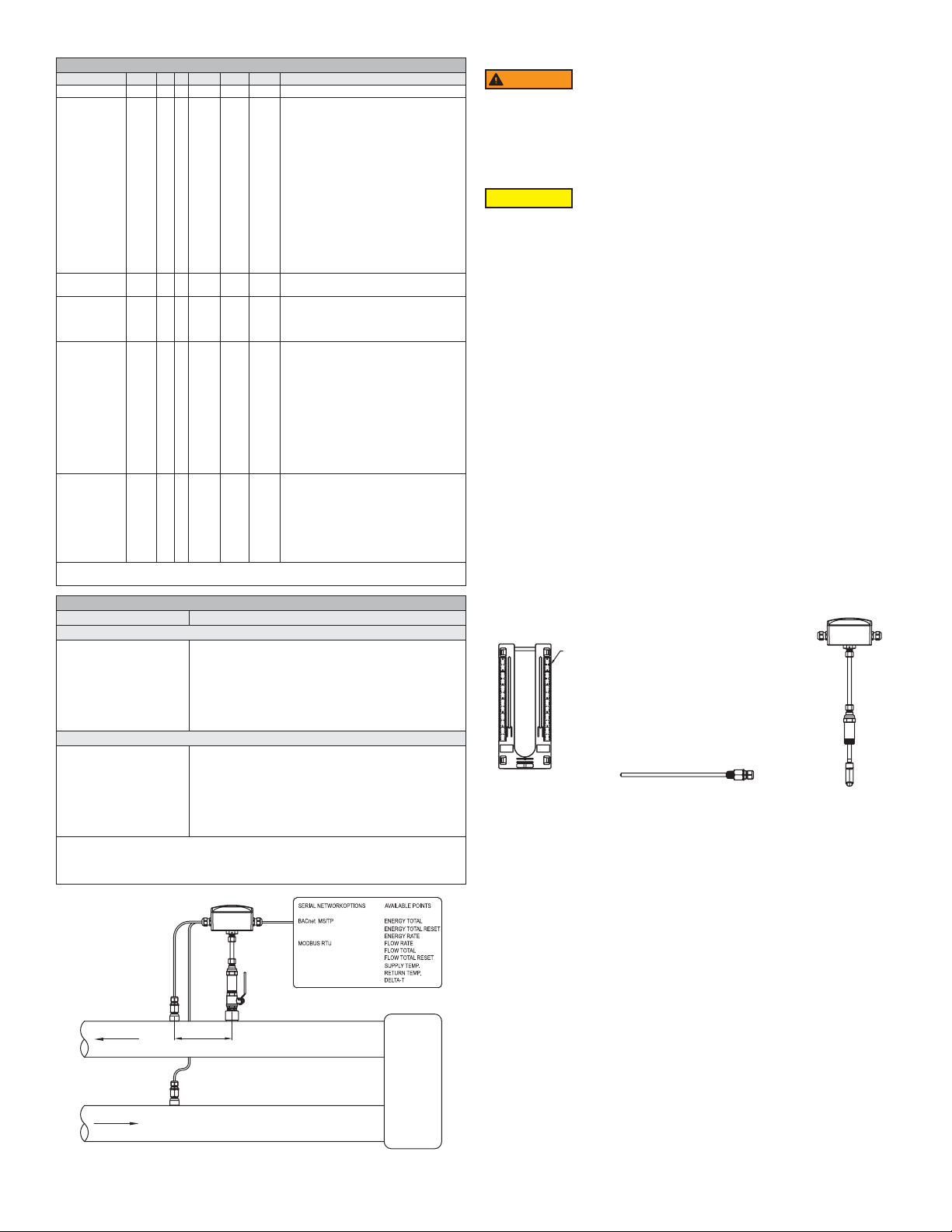
THERMOWELL MODEL CHART
Model A B
A-IEFB-THW-4
A-IEFB-THW-6
4-11/16˝ (119.0 mm)
6-11/16˝ (169.8 mm)
Bulletin F-IEFB
5-25/32 (146.8 mm)
7-25/32 (197.6 mm)
-LCD option
IEFB-X-X-TXX
Shown with
A-IEF-VLV-BR
accessory valve
The Series IEFB is a eld-adjustable insertion thermal energy meter that uses
electromagnetic technology to accurately and reliably measure uid velocity and
energy consumption. The high accuracy IEFB is adjustable to t pipe sizes from 4 to
10˝ (100 to 250 mm), while the standard accuracy IEFB ts pipe sizes 4 to 36˝ (100 to
900 mm). The owmeter is simple to install and incorporates a temperature meter and
an energy calculator into a single unit. The LCD display provides precise readings of
the meter’s values, including temperature and energy consumption, making it ideal for
installation on chillers, boilers, and other heating and cooling applications. The meter's
high measuring accuracy and long lifetime keeps annual system operating costs at
a minimum. In addition, it offers several output options, including selectable BACnet
MS/TP or Modbus® RTU communications protocol over 2-wire RS-485 and standard
analog, frequency, and alarm outputs.
FEATURES/BENEFITS
• Flexible, eld congurable setup displays (-LCD integral option or remote accessory
A-IEF-DSP) accommodate a variety of application congurations. Application
information is display selectable and includes pipe size, pipe material, liquid type,
analog output, pulse/frequency output, alarm outputs, communication outputs,
damping, and calibration factor
• High performance accuracy is maintained through changes in temperature, density
and/or viscosity
• The Setup Wizard and installation tool are simple to use, providing quick and precise
installation
• Accessory setup kit A-IEF-KIT comes with a thickness gage and measuring tape to
ensure exact installation depth
• The meter has no moving parts and electrodes that discourage fouling, which gives
the meter a long lifecycle and minimizes the need for maintenance
• Hot-tap isolation valve accessories allow for easy installation and removal in
operational systems without system downtime
APPLICATIONS
• Monitoring chiller cooling output performance
• Industrial boiler heating performance
• Energy efciency monitoring
• Optimization of heat energy performance
• Commercial and residential heat energy consumption and metering
• District heating and cooling monitoring
• Energy cost allocation monitoring
A-IEFB-THW-XXIEFB-X-X-TXX Hot-tap thermowells for model
IEFB-X-X-RXX (2), shown
with A-IEFB-VLV-BR-1
accessory valve
8-23/64 [212.2]
5-53/64
[148.0]
21-1/64
[533.6]
22-1/64
[559.0]
61/64
SPECIFICATIONS
Service: Compatible clean or dirty non
coating, conductive liquids.
Range: 0 to 20 ft/s (0 to 6 m/s).*
Wetted Materials: Body shaft/tting: 316
SS; Electrodes: 316 SS; Electrode cap:
Polymer/polystyrene; O-ring: Silicone;
Thermowells: 304 SS.
BTU Accuracy per EN1434/ASTM
E3137/CSA C900.1-13: High Accuracy
Units: Class 2 for 2 to 20 ft/s (0.6 to 6
m/s)**; Standard Accuracy Units: Class 3
for 6.5 to 20 ft/s (2 to 6 m/s)**.
Flow Sensor Accuracy: High Accuracy
Units: ±0.5% of reading at calibrated
velocity, ±1% of reading from 2 to 20 ft/s
(0.6 to 6 m/s) ±0.02 ft/s (±0.006 m/s) at <
2 ft/s (0.6 m/s); Standard Accuracy Units:
±1% FS.
Temperature Accuracy: Class B ±(0.30
+ 0.005*t)°C per EN60751.
Differential Temperature Accuracy: Et
= ±(0.5 +3*ΔΘmin/ΔΘ) % per EN1434.
Calculator Accuracy: Ec = ±(0.5
+ΔΘmin/ΔΘ) % per EN1434.
Temperature Compensation: 140 to
220°F (60 to 104.4°C) < 2% error over
±30°F (-1.1 °C) change, 40 to 70°F
(4.4 to 21.1°C) < 2% error over ±10°F
(-12.2°C) change.
Temperature Limits: Ambient: -20 to
160°F (-29 to 71°C), -LCD -4 to 158 °F
(-20 to 70 °C); Process: 15 to 250°F (-9
to 121°C); Storage: -40 to 185°F (-40 to
85°C).
Process Connection: Flowmeter: 1˝
NPT or BSPT with accessory full port ball
valve options; Thermowell: (2) 1/2˝ NPT
or BSPT thermowell with 1˝ full port ball
valve options.
Pressure Limit: 400 psi (27.6 bar) @
100°F (37.8°C).
Pressure Drop: < 0.1 psi at 12 ft/s in 4˝
(<0.01 bar at 3.7 m/s in 100 mm) and
larger pipe.
Outputs: (1) Analog: 4-20 mA, 0-5 V,
0-10 V or 2-10 V (display selectable);
(1) Pulse/Frequency: 0-15 V peak
pulse, 0-500 Hz or scalable pulse output
(display selectable); (2) Alarm: Empty
pipe detection or minimum/maximum
velocity, (display selectable) & Reverse
ow output indication.
*For max owrates >10 ft/s (3 m/s) order option -CC.
** Veried at standard temperature 73.4°F (23°C) refer to listed standards for
detailed accuracy formulations.
[148.0]
[121.9]
13-25/32
[350.0]
B
A
A-IEFB-THW-XX (2) IEFB-X-X-RXX (2)
Power Requirements: 12-42 VDC, .25 A
@ 24 VDC; 12-36 VAC.
Electrical Connection: Removable
terminal blocks, (2) model selectable 1/2˝
female NPT conduit connection, (2) PG
16 gland or (2) PG 16 gland with 10 ft (3
m) 9 conductor 22 AWG plenum rated
cables, accessory cable lengths up to
200 ft (61 m) optional.
Display (-LCD option): 2 x 2˝ (50 x 50
mm) graphic LCD with backlight.
Conductivity: >20 microsiemens.
Enclosure Material: Powder coated die
cast aluminum.
Enclosure Ratings: NEMA 6P (IP68)
(Non display models); NEMA 4X (IP66)
(-LCD option).
Agency Approvals: BTL.
COMMUNICATIONS (-COM OPTION)
Type: BACnet MS/TP or Modbus®
RTU communication protocol (default
disabled, display selectable).
Supported Baud Rates: 9600, 19200,
38400, 57600, 76800, or 115200 bps
(display selectable).
Device Load: 1/8 unit load.
ADDITIONAL SPECIFICATIONS
Applicable Pipe Material: Most popular
plastic and metal pipes; i.e. Carbon steel,
SS, copper, UPVC/PVDF, galvanized
steel, mild steel, and brass.
Applicable Pipe Size: 4 to 36˝ (100 to
900 mm), model dependent. See model
chart.
Diameter Length Requirements: >10
upstream, >5 downstream.
Temperature Resistance: Matched 4
wire platinum RTD’s.
Relative Humidity: 10 to 90% non-
condensing.
Output Impedance: 4-20 mA: 536 Ω;
5V: 500 Ω; 10V: 1.27k Ω.
12-11/16
[322.2]
DWYER INSTRUMENTS, INC.
P.O. BOX 373 • MICHIGAN CITY, INDIANA 46360, U.S.A.
Modbus® is a registered trademark of Schneider Automation, Inc.
1
Phone: 219/879-8000
Fax: 219/872-9057
www.dwyer-inst.com
e-mail: info@dwyermail.com
Page 2
MODEL CHART
Example IEFB -L N -CND -R10 -LCD IEFB-LN-CND-R10-LCD
Series IEFB Insertion thermal energy meter
Accuracy L
G
S
F
I
E
T
H
Process
Connection
Housing
Electrical
Connection
Temperature
Sensors
Options LCD
*Thermowells not included. Refer to thermowell accessory model chart to purchase
permanent thermowells.
ACCESSORIES
Model Description
Thermowells
A-IEFB-THW-4
A-IEFB-THW-6
A-IEFB-THW-4-BSPT
A-IEFB-THW-6-BSPT
Hot-Tap Valves
A-IEFB-VLV-BR-1
A-IEFB-VLV-SS-1
A-IEFB-VLV-BR-1-BSPT
A-IEFB-VLV-SS-1-BSPT
*4˝ (100 mm) standard thermowells for 1-1/2˝ stack height: 4 to 7˝ (100 to 175 mm)
pipe size
**6˝ (150 mm) standard thermowells for 1-1/2˝ stack height: 8 to 10˝ (200 to 350
mm) pipe size. Ideal insertion depth is 3˝ (80 mm)
N
B
CND
PG
10
T10
T20
T50
R10
R20
R50
(2) 1/2˝ NPT, 4˝ (100 mm) thermowell for 4 to 7˝ (100 to
175 mm) pipe*
(2) 1/2˝ NPT, 6˝ (150 mm) thermowell for ≥8˝ (200 mm)
pipe**
(2) 1/2˝ BSPT, 4˝ (100 mm) thermowell for 4 to 7˝ (100
to 175 mm) pipe
(2) 1/2˝ BSPT, 6˝ (150 mm) thermowell for ≥8˝
(200 mm) pipe
(2) 1˝ NPT full port isolation valve brass for temperature
sensor with 1˝ branch outlet and 1˝ nipple
(2) 1˝ NPT full port isolation valve 316 SS for
temperature sensor with 1˝ branch outlet and 1˝ nipple
(2) 1˝ BSPT full port isolation valve brass for
temperature sensor with 1˝ branch outlet and 1˝ nipple
(2) 1˝ BSPT full port isolation valve 316 SS for
temperature sensor with 1˝ branch outlet and 1˝ nipple
Standard accuracy <10˝ (250 mm)
pipe; 1% FS
Standard accuracy >10˝ (250 mm)
pipe; 1% FS
Standard accuracy 4 to 36˝ (100 to
900 mm) pipe; 1% FS
High accuracy 4˝ (100 mm) pipe; 1%
of reading
High accuracy 6˝ (150 mm) pipe; 1%
of reading
High accuracy 8˝ (200 mm) pipe; 1%
of reading
High accuracy 10˝ (250 mm) pipe;
1% of reading
High accuracy 4 to 10˝ (100 to 250
mm) pipe; 1% of reading
1˝ Male NPT
1˝ Male BSPT
1/2˝ female NPT
PG 16 gland without cable
PG 16 gland with (2) 10´ (3 m) plenum
rated cables
(2) 10´ (3 m) PT temperature
sensors*
(2) 20´ (6 m) PT temperature
sensors*
(2) 50´ (15 m) PT temperature
sensors*
(2) 10´ (3 m) PT temperature sensors
with hot-tap thermowells
(2) 20´ (6 m) PT temperature sensors
with hot-tap thermowells
(2) 50´ (15 m) PT temperature
sensors with hot-tap thermowells
Integral LCD
COM
BACnet or Modbus® communications
protocol
NIST
NIST traceable calibration
certication for ow and temperature
FC
Factory calibration certication,
±0.5% of reading at selected velocity
CC
Custom conguration (required input)
Safety Information
WARNING
• Only qualied professionals equipped with the necessary required trade skills
should install, remove or service this product. Failure to follow the
proper installation procedures could lead to death or permanent injury.
• This product is intended to be installed in pressurized pipe applications. In this
event, product will be under pressure, caution should be taken to properly vent
system prior to installation or removal of the unit. Failure to do so could result in
equipment damage and/or serious bodily injury.
CAUTION
• Refer to Model Chart and Specications for the applicable options to your unit.
• Ensure the unit is solidly grounded as stated in this bulletin.
• Depressurize and vent systems without Hot-tap valve prior to installation or
removal.
• Conrm the Series IEFB wetted material is chemically compatible with process
media prior to installation and use.
• Do not exceed maximum temperature and pressure specications.
• Wear appropriate personal protective equipment during installation, removal and or
service of the unit.
• Altering the product construction may adversely affect product operation
and voids warranty.
OPERATING PRINCIPLE
• Per Faraday’s Law of electromagnetic induction, a voltage is induced in a
conductor when the uid passes through a magnetic eld, and the induced voltage
will be directly proportional to the velocity of the conductor.
• The Series IEFB Insertion Thermal Energy Meter generates pulsating magnetic
elds in the probe to induce a voltage into a conductive uid owing through the pipe.
• Electrodes located on the probe measure the induced voltage. Electronics and
rmware within the enclosure convert the voltage to velocity and ow rate while
using various outputs to convey the data to connected systems (i.e. display
devices, data acquisition systems, etc.).
• The IEFB energy calculations are based on ow and temperature measurements
while compensating for density and heat content.
INCLUDED WITH THE SERIES IEFB INSERTION THERMAL ENGERY METER
• Carefully unpack the shipping container of your new Series IEFB Insertion Thermal
Energy Meter and remove the following items:
• (1) Series IEFB insertion thermal energy meter
• (2) RTDs – Temperature measuring probes (not shown)
• (1) A-IEF-INGD installation alignment kit:
◦ (1) Alignment scale with captive thumbscrews
◦ (2) Alignment rods (not shown)
• (1) 3 mm Allen wrench (not shown, located in IEFB hanging tag)
• (2) Hot tap thermowells (model dependent)
• (1) Thermal paste (not shown)
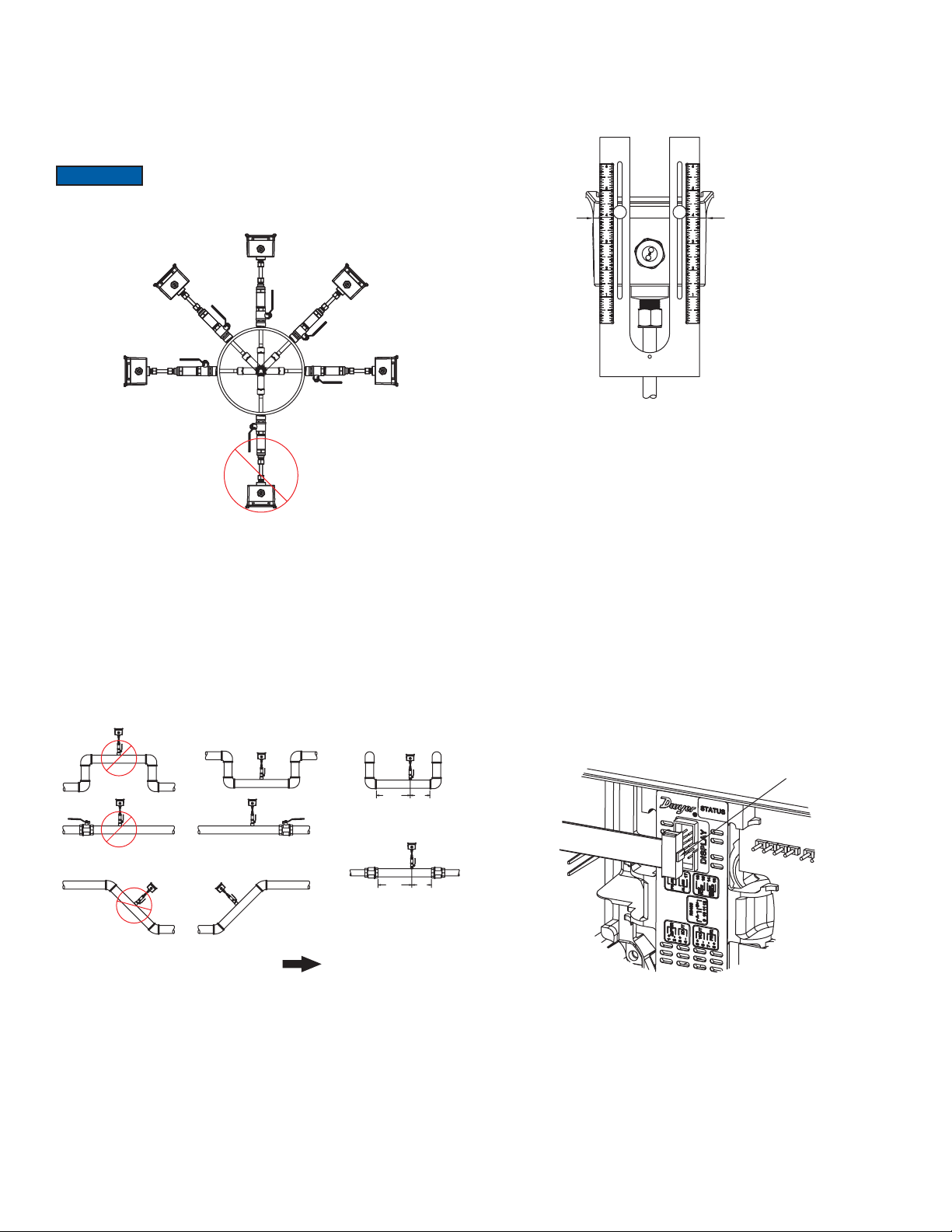
RULER
(2 PLACES)
Alignment
scale (1)
Thermowells (2)
Figure 2: Included with IEFB
Series IEFB
OUTLET
INLET
MAX. 12˝
MIN. 3˝
LOAD
Figure 1: Typical installation
2
Page 3
RECOMMENDED TOOLS
• (2) 12˝ (300 mm) adjustable wrenches
• (1) 12˝ (300 mm) pipe wrench
SETUP
Selecting Installation Location
1. Although the unit may be installed in any orientation, the ideal mounting position
is on the side of the pipe (2 o’clock or 10 o’clock position)* as this generally
minimizes possible air or sediment interference with the Series IEFB. It is not
recommended to mount the unit below the pipe (6 o’clock position).
When installing a unit with an integral display select an installation
NOTICE
location that allows for clear viewing of the display and earth
2. Insert the IEFB in a pipe via a threaded Tee, Saddle, or welded integrally
reinforced branch connection outlet tting.
ground.
IEFB THERMAL ENERGY METER INSTALLATION
FLOWMETER INSTALLATION
1. To prepare the meter for installation, mount the provided alignment scale to the
side of the meter using the two captured thumbscrews, nger tighten only. Be
sure to orient the alignment scale as shown in Figure 5 below. Actual scale
setting determined in next step.
USE LID TO
ENCLOSURE
GAP AS
INDICATOR LINE
*
Figure 3: Proper installation orientation
a. If a Hot-Tap option is required for the IEFB, use a 1-1/4˝ valve kit with proper
mounting hardware available in Model A-IEF-VLV-BR or A-IEF-VLV-SS.
A 1˝ (25 mm) hole in the pipe is required for proper installation.
b. If a Hot-Tap option is required for the RTD thermowells, use a 1˝ valve kit
with proper mounting hardware available in Model A-IEFB-VLV-BR-1 or
A-IEFB-VLV-SS-1. A 1˝ (25 mm) hole in the pipe is required for proper
installation.
3. Select a location that will minimize ow distortion with adequate upstream and
downstream pipe diameters as displayed. Ideal installation will have a minimum
of 10 pipe diameters upstream relative to the instrument and a minimum distance
of 5 pipe diameters downstream.
NOT RECOMMENDED RECOMMENDED
*
5x
20x
Figure 5: Alignment scale installed on IEFB
For Custom Congured Models (-CC Option) only. For eld congurable
models, move to the next section.
2. Use the conguration tag attached to the Series IEFB to identify the value of
the alignment scale setting. Position the alignment scale such that the scale
setting is lined-up with the seam of the enclosure as shown in Figure 5. Securely
tighten the thumbscrews.
3. Skip to Preparing the Unit for Installation.
Note: Minor scale marks are in 1/20ths and take in to account total installation depth.
For Field Congurable Models
2. For eld conguration, a display is required (-LCD option or accessory
A-IEF-DSP) and needs to be powered via normal eld wiring or with the AC wall
adapter accessory A-IEF-PA ( A-IEF-DSP and A-IEF-PA are also available in
the accessory setup kit A-IEF-KIT).
a. When using the AC wall adapter and the cable supplied, connect the red
(positive +) and black (common -) wires of the cable bundle marked “A” to
the open terminals of the AC wall adapter. This will provide temporary power
to the meter to complete the installation set up.
b. For eld wiring, refer to the wiring chart tag attached to the Series IEFB
to identify the terminal block pins for positive (+) and common (-) connection.
If prewired, refer to wiring chart located on the tag.
c. Unscrew the four captured cover screws using the supplied 3 mm Allen
wrench to remove and set aside enclosure cover.
d. If using an A-IEF-DSP or the A-IEF-KIT, insert one connector of the ribbon
cable supplied in the setup kit into the connector labeled “Display” in the
middle of the unit. Be sure to orient the keying feature/tab. See Figure 6
below:
KEYING
FEATURE
FLOW DIRECTION
Figure 4: Proper installation location
20x
5x
Figure 6: Connecting the display for eld congurable models
3
Page 4

3. Plug the other end of the cable into the bottom of A-IEF-DSP or A-IEF-KIT.
PIPE ALIGNMENT ROD MUST
1
8
Orient the keying feature/tab as shown:
KEYING
Figure 7: Keying feature
4. Apply power to the unit to turn on the display. Follow the on-screen directions
for entering the necessary parameters to set up the unit. Obtain the alignment
scale setting values and record them below:
A. IEFB “Alignment Scale Value”
_______________________
This is the value needed for owmeter installation.
Preparing the Unit for Installation
NOTICE
obtain these measurements. When the precise pipe measurement information is
known, select Option 2, High Performance setup, within the pipe setup menu.
Precise pipe measurements are required for high performance
installation. The A-IEF-KIT includes setup display A-IEF-DSP,
thickness gage UTG and measuring tape A-IEF-MSTP used to
FEATURE
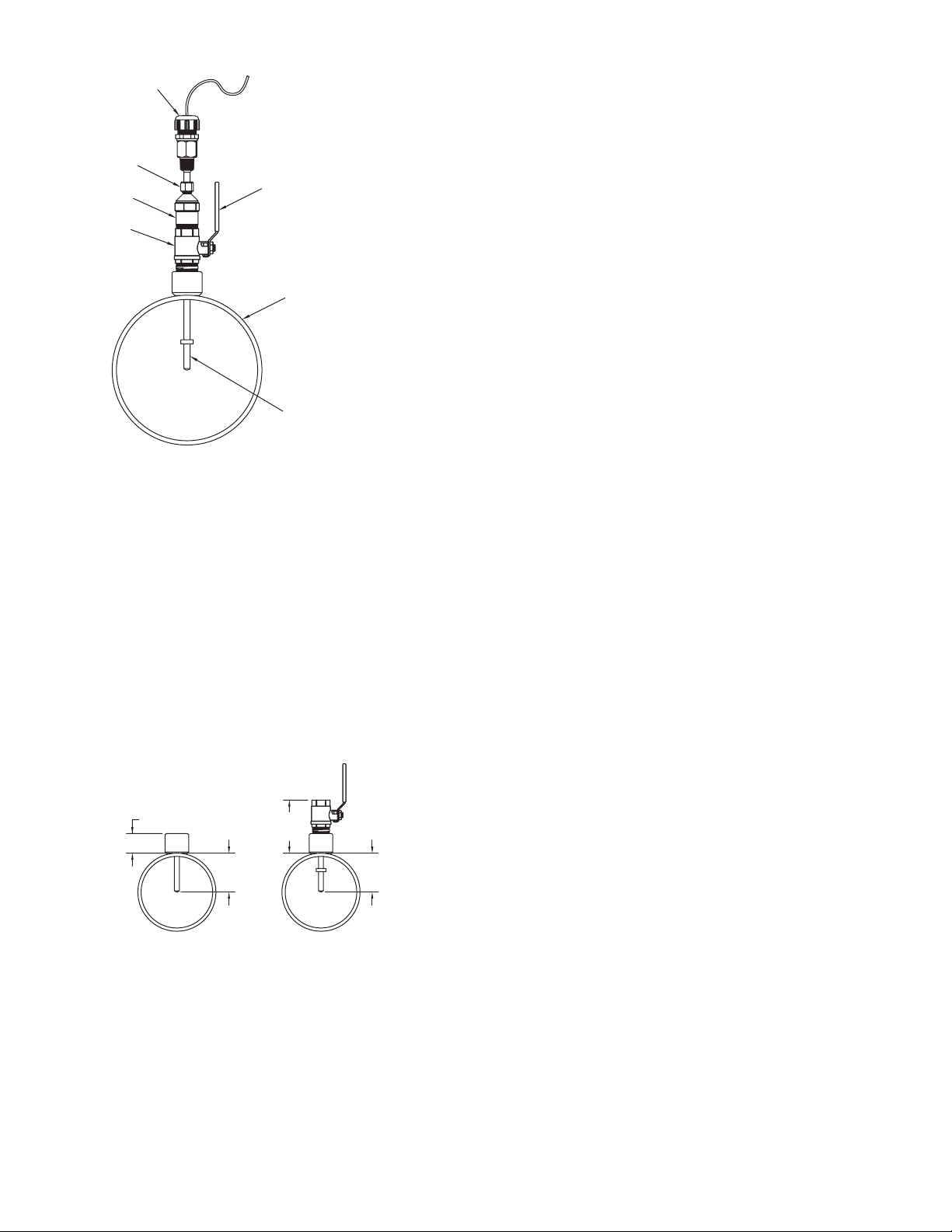
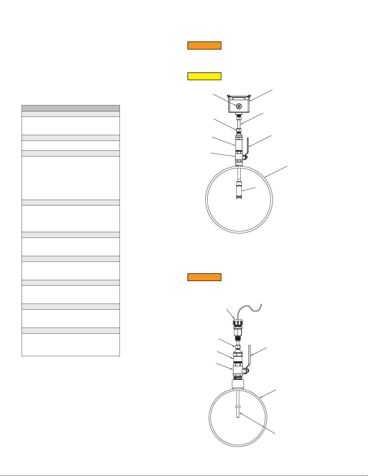
Sensor Alignment
A depth and ow alignment installation tool is provided to ensure proper depth insertion
and ow alignment. To set the insertion depth, verify the alignment scale is set to the
alignment scale value recorded previously as shown in gure 9 below.
Loosen compression nut (4) to allow the shaft (3) freedom to travel up and down and
rotate inside the process collet (5).
Note: Maintain the scale value recorded in step 4A from section "For Field Congurable
Models."
Install Depth and Alignment Rods
1. Remove alignment rods from sides of alignment scale by sliding them out.
2. Insert the two rods into the alignment scale as shown in Figure 10.
USE LID TO
ENCLOSURE
GAP AS
INDICATOR LINE
NOTICE
Preparing the Unit for installation (Figure 8)
1. Apply appropriate sealant to the process collet threads (5) such as sealant tape
or paste as suitable for the application.
2. Install the process collet (5) in valve (6), then tighten by hand.
3. Using the hex geometry, tighten the process collet (5) with a wrench to 180 in-lbs.
4. Slowly open the valve handle (7), checking for leaks. If leaks occur around
threaded connections, close the valve and tighten those connections.
NOTICE
Do not adjust housing compression nut at top of probe shaft (3).
NOTICE
2
4
5
6
When using measuring tape A-IEF-MSTP to measure pipe
circumference, use the 100ths side to measure the circumference
of the pipe (without insulation).
Use two wrenches, one to hold the valve and another wrench to
turn the process collet.
3
7
1. Enclosure
2. Cable Nut
9
3. Probe Shaft
4. Compression Fitting
5. Process Collet
6. Valve
7. Valve Handle
8. Pipe
9. Sensor Probe
Figure 9: IEFB thermal energy meter alignment scale
ALIGNMENT
RODS
Figure 10: IEFB thermal energy meter alignment scale
3. Rotate the meter so the pipe alignment rod is parallel with the ow in the pipe.
BE PARALLEL WITH PIPE
Figure 11: Flow alignment rod
4. Slide the shaft (3) down into the process collet (5) until the depth rod contacts the
pipe. If pipe insulation is present, press the rod through the insulation.
a. Tighten the compression nut (4) to 180 in lbs. (20.3 N m)
b. Remove the ow alignment rod. Loosen the thumbscrews and slide the
alignment tool up to remove the depth alignment rod.
c. Store both rods in the storage slots on the sides of the alignment scale.
Tighten thumbscrews and leave alignment tool mounted on unit for storage.
Figure 8: Side system view
4
Page 5
1
6
3.000
2
3
4
Figure 12: Hot tap installed in pipe cross section
RTD INSTALLATION
Standard Thermowells
When installing temperature sensors in a new or drained uid system, the IEFB uses
standard thermowells.
For accurate energy usage measurement, the temperature sensors in the inlet and
outlet must be located in ideal positions. One thermowell will be installed in the
downstream run of pipe as the IEFB (minimum of 3˝ (75 mm) and no more than 12˝
(300 mm) from the owmeter.) The second thermowell will be placed in the return path
of the measured system.
Note: Ensure the selected locations for the thermowells are at suitable distances given
the length of the RTD cable lengths provided.
Select the appropriate standard thermowell size for the application pipe size. 4˝ (100
mm) and 6˝ (150 mm) Standard Thermowells are available. The pipe size ranges are
listed below:
4˝ (100 mm) Standard Thermowells for 1-1/2˝ Maximum Stack Height:
4 to 7˝ (100 to 175 mm) Pipe Size
6˝ (150 mm) Standard Thermowells for 1-1/2˝ Maximum Stack Height:
8 to 36˝ (200 to 250 mm) Pipe Size
Ideal insertion depth is 3˝
5
1. Cable Gland or Conduit Fitting
2. Compression Fitting
3. Process Collet
4. Valve (optional)
5. Valve handle (optional)
6. Pipe
7. Thermowell
7
Hot Tap Thermowell Sensor Depth
1. Insert the thermowell into the process collet (3) by loosening compression nut (2).
Screw into process valve (4) open the valve by turning valve handle (5).
2. Fully insert thermowell to maximum depth.
a. If thermowell makes contact with pipe ID, retract 1/4˝ (65 mm).
3. Tighten the nut (2) to 15 ft.-lbs (20.3 N m).
4. Repeat steps 1 through 3 for insertion of the second thermowell.
Note: For best accuracy, insulate the portion of the thermowells that is outside the
pipe.
1.500
MAX.
5.500
MAX.
3.000
MIN.
Figure 13: Stack height
MIN.
5
Page 6
RTD INSTALLATION
The Series IEFB is provided with a matched pair of temperature sensors. These
temperature sensors must be wired to the IEFB and properly installed into the
accessory thermowells.
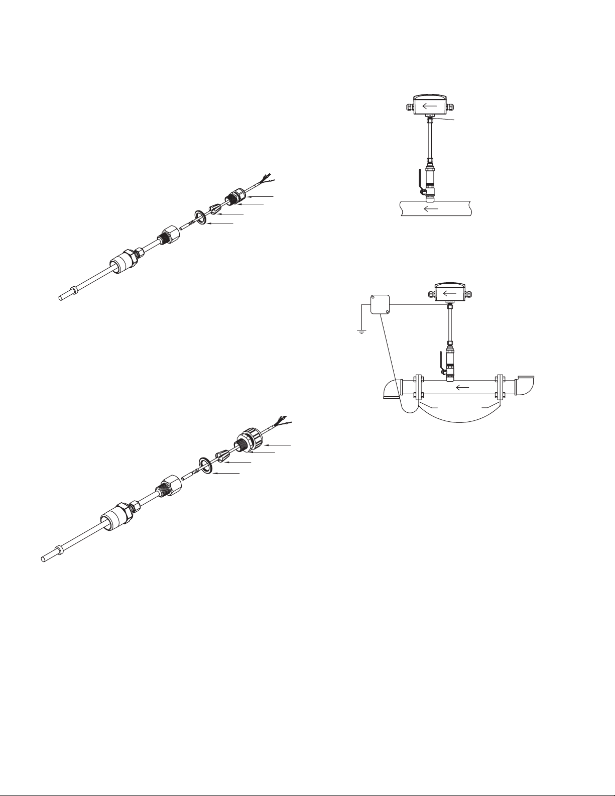
Cable Gland (PG 16) Thermowell (refer to Figure 14 below)
1. Remove compression nut (1) by unscrewing from cable gland (2).
2. Remove insert (3) from the cable gland (2).
3. Route the RTD through compression nut (1) and cable gland (2), then into the
insert (3) and washer (4).
Note: Ensure insert (3) is oriented correctly, as shown in Figure 14 below.
4. Apply a generous coating of provided thermal paste onto the RTD.
5. For best accuracy, rmly insert the RTD into the thermowell, ensuring the tip of
the RTD touches the bottom of the thermowell.
6. Screw the cable gland (2) into the thermowell.
7. Tighten the compression nut (1) onto the cable gland (2) to 30 in/lbs.
2
1
3
4
1. Compression nut
2. Cable gland
3. Insert
4. Washer
Figure 14: Thermowell assembly with PG gland
GROUNDING
Metallic Pipe
For proper operation, the IEFB must be earth grounded.
1. Connect a ground wire to meter housing via the ground lug on the housing collet.
2. Connect the ground wire to a known earth ground.
a. If the pipe is grounded, connect the ground wire to the pipe using suitable
devices such as grounding clamps.
GROUNDING
LUG
Figure 16: Metalic grounding
Non-Metallic Pipes
1. Connect a ground wire to the meter housing per the ground lug on the housing
collet.
2. Connect the ground wire to a known earth ground.
3. Ground the uid to earth.
Conduit Fitting Thermowell (refer to Figure 15 below)
1. Pull the RTD through the conduit.
2. Push the RTD through the conduit tting. Route the RTD through compression
nut (1) and conduit tting (2), then into the insert (3) and washer (4).
3. Apply a generous coating of provided thermal paste onto the RTD.
4. Firmly insert the RTD into the thermowell ensuring the tip of the RTD touches the
bottom of the thermowell.
5. Tighten the conduit tting into the thermowell to 30 in/lbs.
6. Secure the conduit into the conduit tting.
2
1
3
4
1. Compression nut
2. Cable gland
3. Insert
4. Washer
Figure 15: Thermowell assembly with CND gland
GROUNDING
RINGS
Figure 17: Non-metalic grounding
POWER SUPPLY
1. Choose a power supply with a voltage and current rating that meets the power
specications under all operating conditions.
2. If the power supply is unregulated, make sure the output voltage remains within
the required voltage range under all power line conditions.
6
Page 7
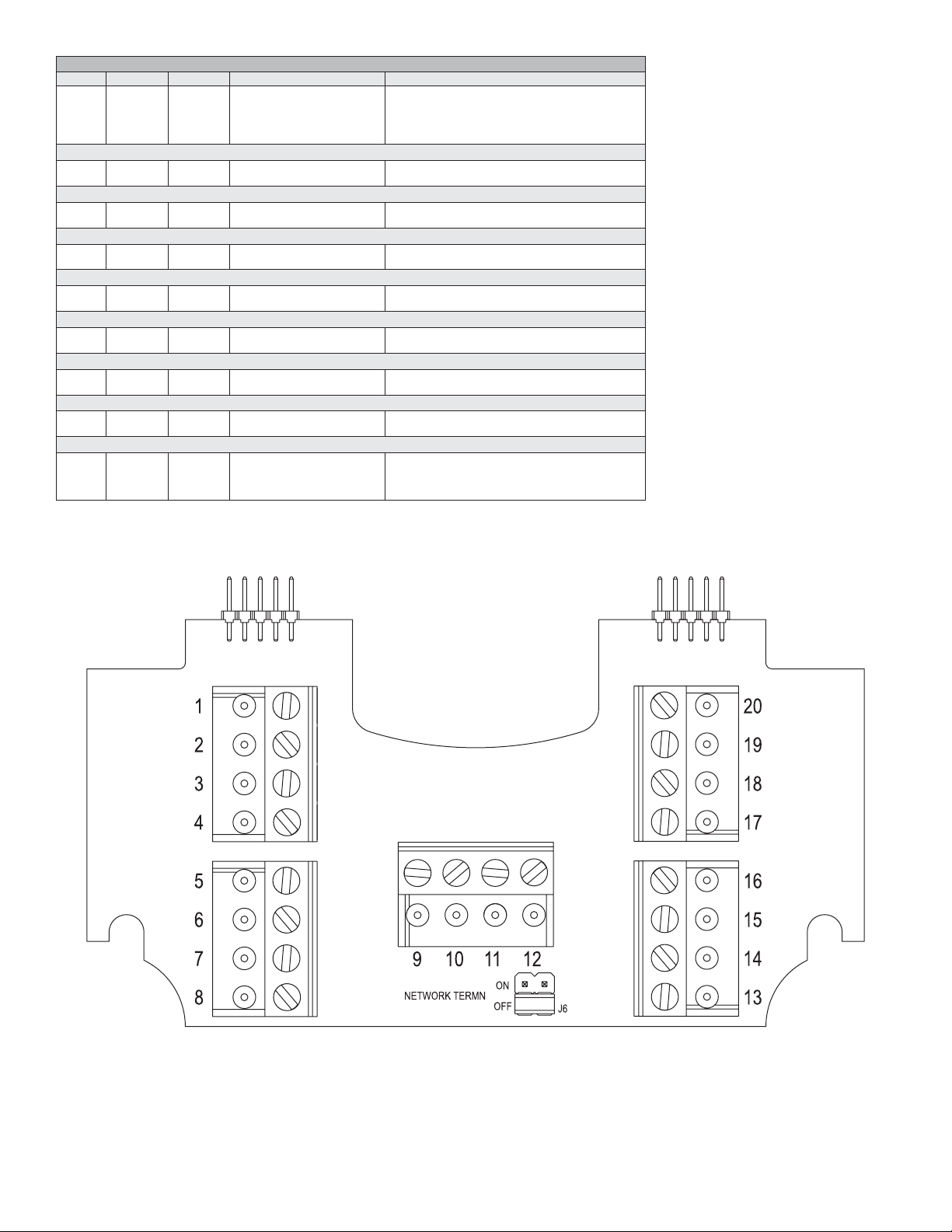
WIRING DIAGRAM
Cable Terminal # Wire Color Description Note
A
A
A
B
External
Analog Current Output
B
B
Analog Voltage Output
B
B
Frequency Output
B
B
RS-485 Communication (optional)
B
B
Reverse Flow
A
A
Alarm
A
A
Pulse
A
A
No Connection
B
B
A
A
1
2
13
14
3
4
5
6
8
7
11,12
9,10
15
16
17
18
19
20
-
-
-
-
Red
Black
Shield
Shield
-
Brown
Blue
Green
White
Violet
Grey
Orange
Yellow
Brown
Blue
Green
White
Orange
Yellow
Red
Black
Violet
Grey
Power Supply Positive
Power Supply Common
-
Earth/Chassis Ground
(+) Analog current output
(-) Analog output common
(+) Analog voltage output
(-) Analog output common
(+) Frequency output
(-) Analog output common
RS-485 (+)
RS-485 (-)
Isolated solid state output N.O.
Isolated solid state output N.O.
Isolated solid state output N.O.
Isolated solid state output N.O.
Isolated solid state output N.O.
Isolated solid state output N.O.
Do not connect
Do not connect
Do not connect
Do not connect
Connect to +24VDC or VAC transformer
Connect to 24VDC/VAC common
If used - Application Dependant
If used - Application Dependant
-
4 to 20 mA process output
Current output common
May be congured; 0 to 10 V, 0 to 5 V, 2 to 10 V, etc.
Voltage output common
0 to 500 Hz output (@ 0/15 VDC output level)
Frequency output common
On board short for daisy chain connection
On board short for daisy chain connection
50 V AC/VDC @ 100 mA maximum
50 V AC/VDC @ 100 mA maximum
50 V AC/VDC @ 100 mA maximum
50 V AC/VDC @ 100 mA maximum
50 V AC/VDC @ 100 mA maximum
50 V AC/VDC @ 100 mA maximum
-
-
-
-
The Cable column identifying cable A and B is reective of units that include factory installed cabling.
Wiring PCBA shown in Figure 18 with terminal block numbers as listed in above wiring diagram chart.
Figure 18: PCBA
7
Page 8
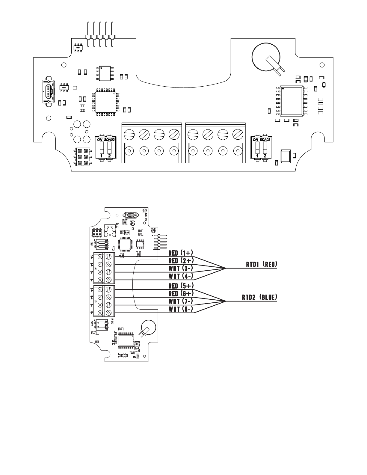
Figure 19: PCBA
Figure 20: Wiring diagram
8
Page 9
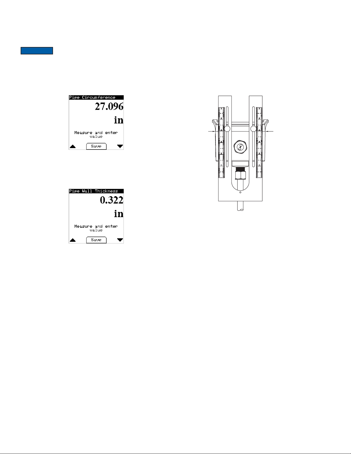
IEFB SETUP
IEFB FLOWMETER SETUP
Determining IEFB probe insertion depth for models with a display
Use the Series IEFB insertion thermal energy meter with -LCD display option or A-IEFDSP to calculate the probe insertion depth.
NOTICE
measuring tape A-IEF-MSTP to obtain these measurements. When the precise pipe
measurement information is known, select High Performance Setup under the Install
Kit Menu when prompted by the display as shown below.
1. To measure the pipe circumference, remove any existing insulation at the location
where the meter will be installed. Wrap the tape measure around the pipe at the
selected location using the 100ths side of the tape. Record this measurement to
enter later when prompted.
2. To measure the wall thickness of the pipe, use the thickness gage UTG. Follow
the directions provided with the UTG gage and record the thickness to enter later
when prompted.
3. Follow the on-screen directions for entering the circumference and wall thickness
dimensions. See the Electronic Control Data Setup section of this manual for
more information.
Precise pipe measurements are required for a high performance
installation. It is recommended to use the A-IEF-KIT which
includes a setup display A-IEF-DSP, thickness gage UTG and
Determining IEFB probe insertion depth for models without a display
For models without a display, the following formulas allow for calculating the alignment
scale value. Pipe wall thickness charts are also included on the next page.
Pipes <12 in (250 mm) diameter: 7.1625-1/2*D
Pipes 12 in (300 mm) to 36 in (914.4 mm): 7.1625-(0.1*(D-2*WT))+WT
Where D represents the pipe outer diameter and WT represents the pipe wall
thickness, both in inches.
Measurement of the circumference and wall thickness can be accomplished using
A-IEF-KIT, as described in the previous section, or similar method. Precise pipe
measurements are required for a high performance installation.
Position the alignment scale such that the alignment scale setting is lined-up with
the seam of the enclosure as shown in Figure 21. Minor scale marks are in 1/20ths.
Securely nger tighten the thumbscrews.
USE LID TO
ENCLOSURE
GAP AS
INDICATOR LINE
Figure 21: Alignment scale positioning
9
Page 10
WALL THICKNESS
Carbon Steel
Pipe Diameter (in) DN (mm) SCH5 (in) SCH5 (mm) SCH10 (in) SCH10 (mm) SCH40 (in) SCH40 (mm) SCH80 (in) SCH80 (mm)
4.5
5.563
6.625
8.625
10.75
12.75
14
16
18
20
24
32
36
WALL THICKNESS
Stainless Steel
Pipe Diameter (in) DN (mm) SCH5 (in) SCH5 (mm) SCH10 (in) SCH10 (mm) SCH40 (in) SCH40 (mm) SCH80 (in) SCH80 (mm)
4.5
5.563
6.625
8.625
10.75
12.75
14
16
18
20
24
32
36
WALL THICKNESS
Copper
Pipe
Diameter (in) DN (mm)
4.125
5.125
6.125
8.125
10.25
12.25
14
16
18
20
24
32
36
104.78
130.18
155.58
206.38
257.18
307.98
355.60
406.40
457.20
508.00
609.60
813.00
914.40
114.30
141.30
168.28
219.08
273.05
323.85
355.60
406.40
457.20
508.00
609.60
813.00
914.40
114.30
141.30
168.28
219.08
273.05
323.85
355.60
406.40
457.20
508.00
609.60
813.00
914.40
0.083
0.109
0.109
0.109
0.134
0.156
0.156
0.165
0.165
0.188
0.218
0.250
0.250
0.083
0.109
0.109
0.109
0.134
0.156
0.156
0.165
0.165
0.188
0.218
0.250
0.250
Type K Type L Type M
in mm in mm in mm
0.134
0.160
0.192
0.271
0.341
0.411
0.471
0.471
0.541
0.610
0.680
0.818
1.096
3.400
4.064
4.876
6.883
8.661
10.439
11.963
11.963
13.741
15.494
17.272
20.777
27.838
2.110
2.770
2.770
2.770
3.400
3.960
3.960
4.190
4.190
4.780
5.540
6.350
6.350
2.110
2.770
2.770
2.770
3.400
3.960
3.960
4.190
4.190
4.780
5.540
6.350
6.350
0.114
0.125
0.140
0.200
0.356
0.411
0.459
0.459
0.513
0.568
0.623
0.732
0.950
2.895
3.175
3.556
5.080
9.042
10.439
11.658
11.658
13.030
14.427
15.824
18.593
24.130
0.120
0.134
0.134
0.148
0.165
0.180
0.250
0.250
0.250
0.250
0.250
0.312
0.312
0.120
0.134
0.134
0.148
0.165
0.180
0.188
0.188
0.188
0.218
0.250
0.312
0.312
0.095
0.109
0.122
0.170
0.308
0.356
0.398
0.398
0.445
0.493
0.541
0.636
0.826
3.050
3.400
3.400
3.760
4.190
4.570
6.350
6.350
6.350
6.350
6.350
7.920
7.920
3.050
3.400
3.400
3.760
4.190
4.570
4.780
4.780
4.780
5.540
6.350
7.920
7.920
2.413
2.768
3.098
4.318
7.823
9.042
10.109
10.109
11.303
12.522
13.741
16.154
20.980
0.237
0.258
0.280
0.322
0.365
0.406
0.437
0.500
0.562
0.593
0.688
0.688
0.750
0.237
0.258
0.280
0.322
0.365
0.375
0.375
0.375
0.375
0.375
0.375
0.375
0.375
6.020
6.550
7.110
8.180
9.270
10.310
11.130
12.700
14.270
15.090
17.480
17.480
19.050
6.020
6.550
7.110
8.180
9.270
9.525
9.525
9.525
9.525
9.525
9.525
9.525
9.525
0.337
0.375
0.432
0.500
0.593
0.687
0.750
0.843
0.937
1.031
1.218
1.218
1.218
0.337
0.375
0.432
0.500
0.500
0.500
0.500
0.500
0.500
0.500
0.500
0.500
0.500
8.560
9.530
10.970
12.700
15.090
17.480
19.050
21.440
23.830
26.190
30.960
30.960
30.960
8.560
9.525
10.970
12.700
12.700
12.700
12.700
12.700
12.700
12.700
12.700
12.700
12.700
WALL THICKNESS
PVC
Pipe
Diameter (in) DN (mm)
4.5
5.563
6.625
8.625
10.75
12.75
14
16
18
20
24
32
36
114.00
141.00
168.00
219.00
273.00
324.00
356.00
406.00
457.20
508.00
609.60
813.00
914.40
SCH40 SCH80
in mm in mm
0.237
6.020
0.337
0.258
0.280
0.322
0.365
0.406
0.437
0.500
0.562
0.593
0.687
0.874
0.968
6.550
7.110
8.180
9.270
10.300
11.100
12.700
14.274
15.062
17.450
22.200
24.587
0.375
0.432
0.500
0.593
0.687
0.750
0.843
0.937
1.031
1.218
1.572
1.754
8.560
9.520
11.000
12.700
15.100
17.400
19.000
21.400
23.800
26.187
30.937
39.929
44.552
10
Page 11
WALL THICKNESS
Carbon Steel
Pipe Diameter (in) DN (mm) SCH5 (in) SCH5 (mm) SCH10 (in) SCH10 (mm) SCH40 (in) SCH40 (mm) SCH80 (in) SCH80 (mm)
4.5
5.563
6.625
8.625
10.75
12.75
14
16
18
20
24
32
36
WALL THICKNESS
Stainless Steel
Pipe Diameter (in) DN (mm) SCH5 (in) SCH5 (mm) SCH10 (in) SCH10 (mm) SCH40 (in) SCH40 (mm) SCH80 (in) SCH80 (mm)
4.5
5.563
6.625
8.625
10.75
12.75
14
16
18
20
24
32
36
WALL THICKNESS
Copper
Pipe
Diameter (in) DN (mm)
4.125
5.125
6.125
8.125
10.25
12.25
14
16
18
20
24
32
36
104.78
130.18
155.58
206.38
257.18
307.98
355.60
406.40
457.20
508.00
609.60
813.00
914.40
114.30
141.30
168.28
219.08
273.05
323.85
355.60
406.40
457.20
508.00
609.60
813.00
914.40
114.30
141.30
168.28
219.08
273.05
323.85
355.60
406.40
457.20
508.00
609.60
813.00
914.40
0.083
0.109
0.109
0.109
0.134
0.156
0.156
0.165
0.165
0.188
0.218
0.250
0.250
0.083
0.109
0.109
0.109
0.134
0.156
0.156
0.165
0.165
0.188
0.218
0.250
0.250
Type K Type L Type M
in mm in mm in mm
0.134
0.160
0.192
0.271
0.341
0.411
0.471
0.471
0.541
0.610
0.680
0.818
1.096
3.400
4.064
4.876
6.883
8.661
10.439
11.963
11.963
13.741
15.494
17.272
20.777
27.838
2.110
2.770
2.770
2.770
3.400
3.960
3.960
4.190
4.190
4.780
5.540
6.350
6.350
2.110
2.770
2.770
2.770
3.400
3.960
3.960
4.190
4.190
4.780
5.540
6.350
6.350
0.114
0.125
0.140
0.200
0.356
0.411
0.459
0.459
0.513
0.568
0.623
0.732
0.950
2.895
3.175
3.556
5.080
9.042
10.439
11.658
11.658
13.030
14.427
15.824
18.593
24.130
0.120
0.134
0.134
0.148
0.165
0.180
0.250
0.250
0.250
0.250
0.250
0.312
0.312
0.120
0.134
0.134
0.148
0.165
0.180
0.188
0.188
0.188
0.218
0.250
0.312
0.312
0.095
0.109
0.122
0.170
0.308
0.356
0.398
0.398
0.445
0.493
0.541
0.636
0.826
3.050
3.400
3.400
3.760
4.190
4.570
6.350
6.350
6.350
6.350
6.350
7.920
7.920
3.050
3.400
3.400
3.760
4.190
4.570
4.780
4.780
4.780
5.540
6.350
7.920
7.920
2.413
2.768
3.098
4.318
7.823
9.042
10.109
10.109
11.303
12.522
13.741
16.154
20.980
0.237
0.258
0.280
0.322
0.365
0.406
0.437
0.500
0.562
0.593
0.688
0.688
0.750
0.237
0.258
0.280
0.322
0.365
0.375
0.375
0.375
0.375
0.375
0.375
0.375
0.375
6.020
6.550
7.110
8.180
9.270
10.310
11.130
12.700
14.270
15.090
17.480
17.480
19.050
6.020
6.550
7.110
8.180
9.270
9.525
9.525
9.525
9.525
9.525
9.525
9.525
9.525
0.337
0.375
0.432
0.500
0.593
0.687
0.750
0.843
0.937
1.031
1.218
1.218
1.218
0.337
0.375
0.432
0.500
0.500
0.500
0.500
0.500
0.500
0.500
0.500
0.500
0.500
8.560
9.530
10.970
12.700
15.090
17.480
19.050
21.440
23.830
26.190
30.960
30.960
30.960
8.560
9.525
10.970
12.700
12.700
12.700
12.700
12.700
12.700
12.700
12.700
12.700
12.700
WALL THICKNESS
PVC
Pipe
Diameter (in) DN (mm)
4.5
5.563
6.625
8.625
10.75
12.75
14
16
18
20
24
32
36
114.00
141.00
168.00
219.00
273.00
324.00
356.00
406.00
457.20
508.00
609.60
813.00
914.40
SCH40 SCH80
in mm in mm
0.237
6.020
0.337
0.258
0.280
0.322
0.365
0.406
0.437
0.500
0.562
0.593
0.687
0.874
0.968
6.550
7.110
8.180
9.270
10.300
11.100
12.700
14.274
15.062
17.450
22.200
24.587
0.375
0.432
0.500
0.593
0.687
0.750
0.843
0.937
1.031
1.218
1.572
1.754
8.560
9.520
11.000
12.700
15.100
17.400
19.000
21.400
23.800
26.187
30.937
39.929
44.552
11
Page 12
Printing out conguration values
1
8
6
After installation is complete, a table of conguration values can be printed to insert
into one of the hanging plastic envelopes for future reference. The housing cover/
display needs to be removed to access to the display port, which is necessary to
retrieve the table of conguration values.
1. Unscrew the four captured cover screws using the supplied 3 mm Allen wrench
and remove the enclosure cover. Leave the display cable connected to the main
unit.
2. Insert a mini-USB cable (not included) into the USB connector on the bottom side
of the display PCB.
3. Connect the other end of the cable into a standard USB port in a laptop.
4. The Series IEFB insertion thermal energy meter will appear as a standard USB
drive on the laptop.
5. The le name with the conguration values is in the format of: serial number.txt.
The serial number can be found on the product label on the side of the meter.
6. Print out the conguration values and insert into one of the hanging plastic
envelopes for future reference
7. Re-attach the housing cover/display by tightening the four 3 mm screws.
CONFIGURATION DATA PRINT OUT EXAMPLE
[Flow Meter Information]
MeterTag=Series IEFB
SerialNumber=018M8Y
ModelNumber=IEFB-HN-10-LCD-COM
DateCode=20190319
[Energy Meter Information]
SerialNumber=TestCal4
DateCode=20190101
[Setup Information]
CalibratedBy=
Date=
Units=English
VelocityUnit=ft/s
FlowUnit=ft³/s
MassFlowUnit=lbm/h
VolumeUnit=gal
TemperatureUnit=°F
PowerUnit=kW
EnergyUnit=kWh
[Pipe Conguration]
LiquidType=Water
PipeMaterial=Carbon Steel
PipeDiameter=8 in
PipeWallThickness=Schedule 40
AlignmentScaleValue=2.85
ThermowellDepth=Maximum Depth
[Energy Meter Setup]
FlowMeterLocation=Inlet
RTDLocationMapping=1=Inlet, 2=Outlet
HeatingChangeoverTemperature=77
ProcessPressure=232.060 PSI
[Analog Output]
AnalogOutputType=Current 4-20mA
AnalogOutputVariable=Velocity ft/s
AnalogOutputHigh=20.00
AnalogOutputLow=0.00
[Pulse/Freq. Output Setup]
Pulse/Freq. Output=Pulse
PulseOutputVariable=Total Flow
PulseOutput=7 gal/pulse
PulseWidth=50 ms
[Alarm Output Setup]
AlarmOutput=Velocity Alarm
VelocityAlarmType=Low Limit
VelocityAlarmTrigger=0.10 ft/s
VelocityAlarmHysteresis=0.05 ft/s
[Communication]
CommunicationProtocol=Modbus
NetworkAddress=127
BaudRate=115200
SerialParity=Even
SerialStopbits=1
Removing Series IEFB Insertion Thermal Energy Meter
1. To remove the meter from an installation without a valve, depressurize the pipe
and skip to step 4. If installed with a valve loosen compression tting (4) and
withdraw the meter shaft fully through the valve until it stops.
WARNING
2. Tighten compression tting (4) snug.
3. Close valve (6) via valve handle (7).
4. Remove meter by unscrewing process collet (5) from valve (6).
CAUTION
Removing Thermowells
1. To remove the thermowell from an installation without a valve, depressurize the
pipe and skip to step 4. If installed with a valve, loosen compression tting (2) and
withdraw the thermowell shaft fully through the valve until it stops.
WARNING
2. Tighten compression tting (2) snug.
3. Close valve (4) via valve handle (5).
4. Remove thermowell by unscrewing process collet (3) from valve (4).
Contents under high pressure.
Be sure to support the housing end of the meter to prevent it from
ipping while unscrewing process collet (5) as damage may occur
to the probe ns.
2
4
5
6
Figure 22: IEFB Side System View
Contents under high pressure.
1
2
3
4
3
7
9
1. Enclosure
2. Cable Nut
3. Probe Shaft
4. Compression Fitting
5. Process Collet
6. Valve
7. Valve Handle
8. Pipe
9. Sensor Probe
5
1. Cable gland or conduit tting
12
Figure 23: Hot tap thermowell installed in pipe cross section
2. Compression Fitting
3. Process Collet
4. Valve (optional)
5. Valve handle (optional)
6. Pipe
7. Thermowell
7
Page 13

Network Termination Jumper
NETWORK TERMINATION JUMPER
On the terminal block PCBA there is a jumper, J1 (see Figure 24), that enables or
disables a network termination resistor as dened below:
When the network jumper is in the ON position there is a 120 ohm termination resistor
in place. When the network jumper is in the OFF position there is no termination
resistor in place.
Default: OFF
Figure 24: Network termination jumper
IEFB: Communication Overview
The IEFB supports BACnet MS/TP and Modbus® RTU over 2-wire RS485. Selection of
protocol and conguration of serial parameters require the use of the display.
BACNET
BACnet Object Overview
Supported BACnet Objects
Object Type
Device No No 607XXX “Series IEF 607xxx” or
Analog Input No No AI1
Analog Value No No AV1
Binary Value No No BV1
Bit String
Value
Date Value No No DV1
Multi-State
Value
Positive
Integer Value
Dynamically
Creatable
No No BSV1
No No MSV1
No No PIV1 Energy Hour Counter
Dynamically
Deletable
Object
Identier Object Name
“Series IEFB 607xxx”
AI2
AI3
AV2
AV3
AV4
AV5
AV6
AV7
AV8
AV9
AV10
AV11
AV12
AV13
AV14
AV15
AV16
AV17
BV2
BV3
BV4
BSV2
DV2
DV3
DV4
MSV2
Velocity
Inlet Temperature
Outlet Temperature
Volume Flow
Mass Flow
Total Flow
Power
Total Energy
Heat Energy
Cooling Energy
Differential Temperature
YTD Max Power
YTD Min Power
MTD Max Power
MTD Min Power
Inlet YTD Average
Temperature
Outlet YTD Average
Temperature
Heat Changeover
Temperature
Process Pressure
Ethylene Glycol
Concentration
Reverse Flow
Empty Pipe
Reset Total Flow
Reset Energy Statistics
Flow Meter Status Flags
Energy Meter Status Flags
YTD Max Power Date
YTD Min Power Date
MTD Max Power Date
MTD Min Power Date
Velocity Probe Location
RTD Locations
13
Page 14

BACnet Objects: Device Object
Property Default Value Property Data Type Access
Object Identier
Object Name
Object Type
System Status
Vendor Name
Vendor Identier
Model Name
Firmware Revision
Application Software Version
Location
Description
Protocol Version
Protocol Revision
Protocol Services Supported
Protocol Object Types Supported
Object List
Active COV Subscriptions
Maximum APDU Length Accepted
Segmentation Supported
Local Time
Local Date
UTC Offset
Daylight Savings Status
APDU Timeout
Number of APDU Retries
Max Master
Max Info Frames
Device Address Binding
Database Revision
Property List
Serial Number
Property List
607xxx
“Series IEF 607xxx” “Series IEFB 607xxx”
DEVICE(8)
Property List
“Dwyer Instruments, Inc.”
607
“IEF-??-??-COM”
“?.?”
“?.?.?”
1
14
See PICS
See Table Above
See Table Above
480
NO_SEGMENTATION (3)
0
False
6000
3
127
1
Empty
1
“xxxxxxxx”
BACnetObjectIdentier
CharacterString(40)
BACnetObjectType
BACnetDeviceStatus
CharacterString
Unsigned
CharacterString
CharacterString
CharacterString
CharacterString(32)
CharacterString(32)
Unsigned
Unsigned
BACnetServicesSupported
BACnetObjectTypesSupported
BACnetArray
List of BACnetCOVSubscription
Unsigned
BACnetSegmentation
Time
Date
Integer
Boolean
Unsigned
Unsigned
Unsigned
Unsigned
BACnetAddressBinding
Unsigned
BACnetARRAY[N] of BACnetPropertyIdentier
CharacterString
BACnetARRAY[N] of BACnetPropertyIdentier
Read/Write
Read/Write
Read
Read
Read
Read
Read
Read
Read
Read/Write
Read/Write
Read
Read
Read
Read
Read
Read
Read
Read
Read
Read
Read/Write
Read/Write
Read/Write
Read/Write
Read/Write
Read
Read
Read
Read
Read
14
Page 15

The default object identier is 607xxx, where xxx is replaced by the MS/TP MAC
address set in the Network Address menu. The object identier value will change as
the MS/TP MAC address changes. However, if a specic object identier is written
via BACnet, then that value is stored and changes to the MS/TP MAC address will no
longer affect the object identier.
Similarly, the default object name includes 607xxx. The object name will reect the
current object identier. If a specic object name is written via BACnet, then that value
is stored and changes to the object identier will no longer affect the object name.
APDU Timeout values are rounded to the nearest second (1000ms). Values less than
500 will be rounded to 0 and Number of APDU Retries will be set to 0.
Analog Input – Velocity
Property Default Value Property Data Type Access
Object Identier
Object Name
Object Type
Present Value
Status Flags
Event State
Reliability
Out of Service
Units
COV Increment
Property List
COV Increment Value
Default Value Minimum Value Minimum Value Increment
0.5 ft/s 0.1 ft/s 10.0 ft/s 0.1 ft/s
Supported Units:
Feet-per-second (76), Feet-per-minute (77), Meters-per-second (74), Meters-perminute (163), Meters-per-hour (164), Feet-per-hour (512)*, Feet-per-day (513)*,
Meters-per-day (514)*
*Non-Standard BACnet unit
Analog Input – Inlet Temperature
Property Default Value Property Data Type Access
Object Identier
Object Name
Object Type
Present Value
Status Flags
Event State
Reliability
Out of Service
Units
COV Increment
Property List
COV Increment Value
Default Value Minimum Value Minimum Value Increment
1.0°C 0.1°C 10.0°C 0.1°C
Supported Units:
Degrees-Celsius (62), Degrees-Kelvin (63), Degrees-Fahrenheit (64), DegreesRankine (523)*
*Non-Standard BACnet unit
AI1
"Velocity"
ANALOG_INPUT (0)
Current reading
0
Normal (0)
NO_FAULT_DETECTED (0)
FALSE (0)
Feet-per-second (76)
0.5
AI2
"Inlet Temperature"
ANALOG_INPUT (0)
Current reading
0
Normal (0)
NO_FAULT_DETECTED (0)
FALSE (0)
Degrees-Celsius (62)
1.0
BACnetObjectIdentier
CharacterString
BACnetObjectType
Real
BACnetStatusFlags
BACnetEventState
BACnetReliability
Boolean
BACnetEngineeringUnits
Real
BACnetARRAY[N] of BACnetPropertyIdentier
BACnetObjectIdentier
CharacterString
BACnetObjectType
Real
BACnetStatusFlags
BACnetEventState
BACnetReliability
Boolean
BACnetEngineeringUnits
Real
BACnetARRAY[N] of BACnetPropertyIdentier
Read
Read
Read
Read
Read
Read
Read
Read/Write
Read/Write
Read/Write
Read
Read
Read
Read
Read
Read
Read
Read
Read/Write
Read/Write
Read/Write
Read
15
Page 16

Analog Input – Outlet Temperature
Property Default Value Property Data Type Access
Object Identier
Object Name
Object Type
Present Value
Status Flags
Event State
Reliability
Out of Service
Units
COV Increment
Property List
COV Increment Value
Default Value Minimum Value Minimum Value Increment
1.0°C 0.1°C 10.0°C 0.1°C
Supported Units:
Degrees-Celsius (62), Degrees-Kelvin (63), Degrees-Fahrenheit (64), DegreesRankine (523)*
*Non-Standard BACnet unit
Analog Value – Volume Flow
Property Default Value Property Data Type Access
Object Identier
Object Name
Object Type
Present Value
Status Flags
Event State
Reliability
Out of Service
Units
COV Increment
Property List
COV Increment Value
Default Value Minimum Value Minimum Value Increment
1.0 ft³/s 0.133 ft³/s 13.3681 ft³/s 0.1 ft³/s
Supported Units:
Cubic-feet-per-second (142), Cubic-feet-per-minute (84), Cubic-feet-per-hour (191),
Cubic-feet-per-day (248), US-gallons-per-minute (89), US-gallons-per-hour (192),
Liters-per-second (87), Liters-per-minute (88), Liters-per-hour (136), Cubic-metersper-second (85), Cubic-meters-per-minute (165), Cubic-meters-per-hour (135), USgallons-per-second (515)*, US-gallons-per-day (516)*, Liters-per-day (517)*, Cubicmeters-per-day (518)*
*Non-Standard BACnet unit
AI3
"Outlet Temperature"
ANALOG_INPUT (0)
Current reading
0
Normal (0)
NO_FAULT_DETECTED (0)
FALSE (0)
Degrees-Celsius (62)
1.0
AV1
"Volume Flow"
ANALOG_VALUE (1)
Current reading
0
Normal (0)
NO_FAULT_DETECTED (0)
FALSE (0)
Cubic-feet-per-second (142)
1.0
BACnetObjectIdentier
CharacterString
BACnetObjectType
Real
BACnetStatusFlags
BACnetEventState
BACnetReliability
Boolean
BACnetEngineeringUnits
Real
BACnetARRAY[N] of BACnetPropertyIdentier
BACnetObjectIdentier
CharacterString
BACnetObjectType
Real
BACnetStatusFlags
BACnetEventState
BACnetReliability
Boolean
BACnetEngineeringUnits
Real
BACnetARRAY[N] of BACnetPropertyIdentier
Read
Read
Read
Read
Read
Read
Read
Read/Write
Read/Write
Read/Write
Read
Read
Read
Read
Read
Read
Read
Read
Read/Write
Read/Write
Read/Write
Read
Analog Value – Mass Flow
Property Default Value Property Data Type Access
Object Identier
Object Name
Object Type
Present Value
Status Flags
Event State
Reliability
Out of Service
Units
COV Increment
Property List
COV Increment Value
Default Value Minimum Value Minimum Value Increment
10.0 lbm/s 10.0 lbm/s 100.0 lbm/s 0.1 lbm/s
Supported Units:
Kilograms-per-second (42), Kilograms-per-minute (43), Kilograms-per-hour (44),
Kilograms-per-day (526)*, Pounds-mass-per-second (119), Pounds-mass-per-minute
(45), Pounds-mass-per-hour (46), Pounds-mass-per-day (47812)
*Non-Standard BACnet unit
AV2
"Mass Flow"
ANALOG_VALUE (2)
Current reading
0
Normal (0)
NO_FAULT_DETECTED (0)
FALSE (0)
Pounds-mass-per-second(119)
10.0
BACnetObjectIdentier
CharacterString
BACnetObjectType
Real
BACnetStatusFlags
BACnetEventState
BACnetReliability
Boolean
BACnetEngineeringUnits
Real
BACnetARRAY[N] of BACnetPropertyIdentier
Read
Read
Read
Read
Read
Read
Read
Read/Write
Read/Write
Read/Write
Read
16
Page 17

Analog Value – Total Flow
Property Default Value Property Data Type Access
Object Identier
Object Name
Object Type
Present Value
Status Flags
Event State
Reliability
Out of Service
Units
COV Increment
Property List
COV Increment Value
Default Value Minimum Value Minimum Value Increment
7.48 gal 1.0 gal 100.0 gal 0.1gal
Supported Units:
Cubic-feet (79), US-gallons (83), Liters (82), Cubic-meters (80)
Analog Value – Power
Property Default Value Property Data Type Access
Object Identier
Object Name
Object Type
Present Value
Status Flags
Event State
Reliability
Out of Service
Units
COV Increment
Property List
COV Increment Value
Default Value Minimum Value Minimum Value Increment
1.0 kW 0.1 kW 1000 kW 0.1 kW
AV3
"Total Flow"
ANALOG_VALUE (2)
Current reading
0
Normal (0)
NO_FAULT_DETECTED (0)
FALSE (0)
US-gallons (82)
7.48
AV4
"Power"
ANALOG_VALUE (2)
Current reading
0
Normal (0)
NO_FAULT_DETECTED (0)
FALSE (0)
Kilowatts (48)
1.0
BACnetObjectIdentier
CharacterString
BACnetObjectType
Real
BACnetStatusFlags
BACnetEventState
BACnetReliability
Boolean
BACnetEngineeringUnits
Real
BACnetARRAY[N] of BACnetPropertyIdentier
BACnetObjectIdentier
CharacterString
BACnetObjectType
Real
BACnetStatusFlags
BACnetEventState
BACnetReliability
Boolean
BACnetEngineeringUnits
Real
BACnetARRAY[N] of BACnetPropertyIdentier
Read
Read
Read
Read
Read
Read
Read
Read/Write
Read/Write
Read/Write
Read
Read
Read
Read
Read
Read
Read
Read
Read/Write
Read/Write
Read/Write
Read
Supported Units:
Watts (47), Kilowatts (48), Megawatts (49), Joule-per-hour (247), Kilojoule-per-hour
(520)*, gigajoule-per-hour (521)*, Btus-per-hour (50), Kilo-btus-per-hour (157), Tons-
refrigeration (52)
*Non-Standard BACnet unit
Analog Value – Total Energy
Property Default Value Property Data Type Access
Object Identier
Object Name
Object Type
Present Value
Status Flags
Event State
Reliability
Out of Service
Units
COV Increment
Property List
COV Increment Value
Default Value Minimum Value Minimum Value Increment
1.0 kJ 1.0 kJ 10000 kJ 1.0 kJ
Supported Units:
Kilojoule (17), Megajoule (126), Gigajoule (522)*, Btus (20), Kilo-btus (147), Watthours (18), Kilowatt-hours (19), Megawatt-hours (146), Ton-hours (22)
*Non-Standard BACnet unit
AV5
"Total Energy"
ANALOG_VALUE (2)
Current reading
0
Normal (0)
NO_FAULT_DETECTED (0)
FALSE (0)
Kilojoule (17)
1.0
BACnetObjectIdentier
CharacterString
BACnetObjectType
Real
BACnetStatusFlags
BACnetEventState
BACnetReliability
Boolean
BACnetEngineeringUnits
Real
BACnetARRAY[N] of BACnetPropertyIdentier
Read
Read
Read
Read
Read
Read
Read
Read/Write
Read/Write
Read/Write
Read
17
Page 18

Analog Value – Heat Energy
Property Default Value Property Data Type Access
Object Identier
Object Name
Object Type
Present Value
Status Flags
Event State
Reliability
Out of Service
Units
COV Increment
Property List
COV Increment Value
Default Value Minimum Value Minimum Value Increment
1.0 kJ 1.0 kJ 10000 kJ 1.0 kJ
Supported Units:
Kilojoule (17), Megajoule (126), Gigajoule (522)*, Btus (20), Kilo-btus (147), Watthours (18), Kilowatt-hours (19), Megawatt-hours (146), Ton-hours (22)
*Non-Standard BACnet unit
Analog Value – Cooling Energy
Property Default Value Property Data Type Access
Object Identier
Object Name
Object Type
Present Value
Status Flags
Event State
Reliability
Out of Service
Units
COV Increment
Property List
COV Increment Value
Default Value Minimum Value Minimum Value Increment
1.0 kJ 1.0 kJ 10000 kJ 1.0 kJ
AV6
"Heat Energy"
ANALOG_VALUE (2)
Current reading
0
Normal (0)
NO_FAULT_DETECTED (0)
FALSE (0)
Kilojoule (17)
1.0
AV7
"Cooling Energy"
ANALOG_VALUE (2)
Current reading
0
Normal (0)
NO_FAULT_DETECTED (0)
FALSE (0)
Kilojoule (17)
1.0
BACnetObjectIdentier
CharacterString
BACnetObjectType
Real
BACnetStatusFlags
BACnetEventState
BACnetReliability
Boolean
BACnetEngineeringUnits
Real
BACnetARRAY[N] of BACnetPropertyIdentier
BACnetObjectIdentier
CharacterString
BACnetObjectType
Real
BACnetStatusFlags
BACnetEventState
BACnetReliability
Boolean
BACnetEngineeringUnits
Real
BACnetARRAY[N] of BACnetPropertyIdentier
Read
Read
Read
Read
Read
Read
Read
Read/Write
Read/Write
Read/Write
Read
Read
Read
Read
Read
Read
Read
Read
Read/Write
Read/Write
Read/Write
Read
Supported Units:
Kilojoule (17), Megajoule (126), Gigajoule (522)*, Btus (20), Kilo-btus (147), Watthours (18), Kilowatt-hours (19), Megawatt-hours (146), Ton-hours (22)
*Non-Standard BACnet unit
Analog Value – Cooling Energy
Property Default Value Property Data Type Access
Object Identier
Object Name
Object Type
Present Value
Status Flags
Event State
Reliability
Out of Service
Units
COV Increment
Property List
COV Increment Value
Default Value Minimum Value Minimum Value Increment
1.0°C 0.1°C 10.0°C 0.1°C
Supported Units:
Degrees-Celsius (62), Degrees-Kelvin (63), Degrees-Fahrenheit (64), DegreesRankine (523)*
*Non-Standard BACnet unit
AV7
"Cooling Energy"
ANALOG_VALUE (2)
Current reading
0
Normal (0)
NO_FAULT_DETECTED (0)
FALSE (0)
Kilojoule (17)
1.0
BACnetObjectIdentier
CharacterString
BACnetObjectType
Real
BACnetStatusFlags
BACnetEventState
BACnetReliability
Boolean
BACnetEngineeringUnits
Real
BACnetARRAY[N] of BACnetPropertyIdentier
Read
Read
Read
Read
Read
Read
Read
Read/Write
Read/Write
Read/Write
Read
18
Page 19

Analog Value – YTD Max Power
Property Default Value Property Data Type Access
Object Identier
Object Name
Object Type
Present Value
Status Flags
Event State
Reliability
Out of Service
Units
Property List
Supported Units:
Kilojoule (17), Megajoule (126), Gigajoule (522)*, Btus (20), Kilo-btus (147), Watthours (18), Kilowatt-hours (19), Megawatt-hours (146), Ton-hours (22)
*Non-Standard BACnet unit
Analog Value – YTD Min Power
Property Default Value Property Data Type Access
Object Identier
Object Name
Object Type
Present Value
Status Flags
Event State
Reliability
Out of Service
Units
Property List
Supported Units:
Kilojoule (17), Megajoule (126), Gigajoule (522)*, Btus (20), Kilo-btus (147), Watthours (18), Kilowatt-hours (19), Megawatt-hours (146), Ton-hours (22)
*Non-Standard BACnet unit
Analog Value – MTD Max Power
Property Default Value Property Data Type Access
Object Identier
Object Name
Object Type
Present Value
Status Flags
Event State
Reliability
Out of Service
Units
Property List
Supported Units:
Kilojoule (17), Megajoule (126), Gigajoule (522)*, Btus (20), Kilo-btus (147), Watthours (18), Kilowatt-hours (19), Megawatt-hours (146), Ton-hours (22)
*Non-Standard BACnet unit
Analog Value – MTD Min Power
Property Default Value Property Data Type Access
Object Identier
Object Name
Object Type
Present Value
Status Flags
Event State
Reliability
Out of Service
Units
Property List
Supported Units:
Kilojoule (17), Megajoule (126), Gigajoule (522)*, Btus (20), Kilo-btus (147), Watthours (18), Kilowatt-hours (19), Megawatt-hours (146), Ton-hours (22)
*Non-Standard BACnet unit
AV9
"YTD Max Power"
ANALOG_VALUE (2)
Current reading
0
Normal (0)
NO_FAULT_DETECTED (0)
FALSE (0)
Kilojoule (17)
AV10
"YTD Min Power"
ANALOG_VALUE (2)
Current reading
0
Normal (0)
NO_FAULT_DETECTED (0)
FALSE (0)
Kilojoule (17)
AV11
"MTD Max Power"
ANALOG_VALUE (2)
Current reading
0
Normal (0)
NO_FAULT_DETECTED (0)
FALSE (0)
Kilojoule (17)
AV12
"MTD Min Power"
ANALOG_VALUE (2)
Current reading
0
Normal (0)
NO_FAULT_DETECTED (0)
FALSE (0)
Kilojoule (17)
BACnetObjectIdentier
CharacterString
BACnetObjectType
Real
BACnetStatusFlags
BACnetEventState
BACnetReliability
Boolean
BACnetEngineeringUnits
BACnetARRAY[N] of BACnetPropertyIdentier
BACnetObjectIdentier
CharacterString
BACnetObjectType
Real
BACnetStatusFlags
BACnetEventState
BACnetReliability
Boolean
BACnetEngineeringUnits
BACnetARRAY[N] of BACnetPropertyIdentier
BACnetObjectIdentier
CharacterString
BACnetObjectType
Real
BACnetStatusFlags
BACnetEventState
BACnetReliability
Boolean
BACnetEngineeringUnits
BACnetARRAY[N] of BACnetPropertyIdentier
BACnetObjectIdentier
CharacterString
BACnetObjectType
Real
BACnetStatusFlags
BACnetEventState
BACnetReliability
Boolean
BACnetEngineeringUnits
BACnetARRAY[N] of BACnetPropertyIdentier
Read
Read
Read
Read
Read
Read
Read
Read/Write
Read/Write
Read
Read
Read
Read
Read
Read
Read
Read
Read/Write
Read/Write
Read
Read
Read
Read
Read
Read
Read
Read
Read/Write
Read/Write
Read
Read
Read
Read
Read
Read
Read
Read
Read/Write
Read/Write
Read
19
Page 20

Analog Value – Inlet YTD Average Temperature
Property Default Value Property Data Type Access
Object Identier
Object Name
Object Type
Present Value
Status Flags
Event State
Reliability
Out of Service
Units
Property List
Supported Units:
Degrees-Celsius (62), Degrees-Kelvin (63), Degrees-Fahrenheit (64), DegreesRankine (523)*
*Non-Standard BACnet unit
Analog Value – Outlet YTD Average Temperature
Property Default Value Property Data Type Access
Object Identier
Object Name
Object Type
Present Value
Status Flags
Event State
Reliability
Out of Service
Units
Property List
Supported Units:
Degrees-Celsius (62), Degrees-Kelvin (63), Degrees-Fahrenheit (64), DegreesRankine (523)*
*Non-Standard BACnet unit
Analog Value – Heat Changeover Temperature
Property Default Value Property Data Type Access
Object Identier
Object Name
Object Type
Present Value
Status Flags
Event State
Reliability
Out of Service
Units
Property List
AV13
"Inlet YTD Average Temperature"
ANALOG_VALUE (2)
Current reading
0
Normal (0)
NO_FAULT_DETECTED (0)
FALSE (0)
Degrees-Celsius (62)
AV14
"Outlet YTD Average Temperature"
ANALOG_VALUE (2)
Current reading
0
Normal (0)
NO_FAULT_DETECTED (0)
FALSE (0)
Degrees-Celsius (62)
AV15
“Heat Changeover Temperature”
ANALOG_VALUE (2)
Current reading
0
Normal (0)
NO_FAULT_DETECTED (0)
FALSE (0)
Degrees-Celsius (62)
BACnetObjectIdentier
CharacterString
BACnetObjectType
Real
BACnetStatusFlags
BACnetEventState
BACnetReliability
Boolean
BACnetEngineeringUnits
BACnetARRAY[N] of BACnetPropertyIdentier
BACnetObjectIdentier
CharacterString
BACnetObjectType
Real
BACnetStatusFlags
BACnetEventState
BACnetReliability
Boolean
BACnetEngineeringUnits
BACnetARRAY[N] of BACnetPropertyIdentier
BACnetObjectIdentier
CharacterString
BACnetObjectType
Real
BACnetStatusFlags
BACnetEventState
BACnetReliability
Boolean
BACnetEngineeringUnits
BACnetARRAY[N] of BACnetPropertyIdentier
Read
Read
Read
Read
Read
Read
Read
Read/Write
Read/Write
Read
Read
Read
Read
Read
Read
Read
Read
Read/Write
Read/Write
Read
Read
Read
Read
Read/Write
Read
Read
Read
Read/Write
Read/Write
Read
Present Value
Default Value Minimum Value Minimum Value
25.0°C 0.0°C 120.0°C
The inlet temperature is compared to this value to determine when energy can be
accumulated and if that energy is heat energy.
Supported Units:
Degrees-Celsius (62), Degrees-Kelvin (63), Degrees-Fahrenheit (64), DegreesRankine (523)*
*Non-Standard BACnet unit
Analog Value – Process Pressure
Property Default Value Property Data Type Access
Object Identier
Object Name
Object Type
Present Value
Status Flags
Event State
Reliability
Out of Service
Units
Property List
Present Value
Default Value Minimum Value Minimum Value
232.060 psi 2.901 psi 400.304 psi
This value is used in the energy calculation.
Supported Units:
Pounds-force-per-square-inch (56), Kilopascals (54)
AV16
“Process Pressure”
ANALOG_VALUE (2)
232.0604
0
Normal (0)
NO_FAULT_DETECTED (0)
FALSE (0)
Pounds-force-per-square-inch (56)
BACnetObjectIdentier
CharacterString
BACnetObjectType
Real
BACnetStatusFlags
BACnetEventState
BACnetReliability
Boolean
BACnetEngineeringUnits
BACnetARRAY[N] of BACnetPropertyIdentier
Read
Read
Read
Read/Write
Read
Read
Read
Read/Write
Read/Write
Read
20
Page 21

Analog Value – Ethylene Glycol Concentration
Property Default Value Property Data Type Access
Object Identier
Object Name
Object Type
Present Value
Status Flags
Event State
Reliability
Out of Service
Units
Property List
Present Value
Default Value Minimum Value Minimum Value
0% 0% 100%
This value indicates the amount of Ethylene Glycol by volume in the process uid.
Binary Value – Reverse Flow
Property Default Value Property Data Type Access
Object Identier
Object Name
Object Type
Present Value
Status Flags
Event State
Reliability
Out Of Service
Property List
This value indicates whether or not the direction of the process ow is reversed relative
to the arrow mark on the product label.
Present Value: Inactive (0) – Process uid ow direction not reversed, Active (1) –
Process uid ow direction reversed.
This object supports COV notications.
AV17
“Ethylene Glycol Concentration”
ANALOG_VALUE (2)
0
0
Normal (0)
NO_FAULT_DETECTED (0)
FALSE (0)
Percent (98)
BV1
“Reverse Flow”
BINARY_VALUE (5)
Current Value
0
NORMAL (0)
NO_FAULT_DETECTED(0)
FALSE (0)
BACnetObjectIdentier
CharacterString
BACnetObjectType
Real
BACnetStatusFlags
BACnetEventState
BACnetReliability
Boolean
BACnetEngineeringUnits
BACnetARRAY[N] of BACnetPropertyIdentier
BACnetObjectIdentier
CharacterString
BACnetObjectType
BACnetBinaryPV
BACnetStatusFlags
BACnetEventState
BACnetReliability
Boolean
BACnetARRAY[N] of BACnetPropertyIdentier
Read
Read
Read
Read/Write
Read
Read
Read
Read/Write
Read
Read
Read
Read
Read
Read
Read
Read
Read
Read/Write
Read
Binary Value – Empty Pipe
Property Default Value Property Data Type Access
Object Identier
Object Name
Object Type
Present Value
Status Flags
Event State
Reliability
Out Of Service
Property List
This value indicates whether or not the meter detects process uid at the location of
the probe.
Present Value: Inactive (0) – Process uid detected, Active (1) – Process uid not
detected
This object supports COV notications.
Binary Value – Reset Total Flow
Property Default Value Property Data Type Access
Object Identier
Object Name
Object Type
Present Value
Status Flags
Event State
Reliability
Out Of Service
Property List
Writing a value of 1 to the present value of this object will reset the value of Total Flow
to 0. Writing a value of 0 has no effect.
BV2
“Empty Pipe”
BINARY_VALUE (5)
Current Value
0
NORMAL (0)
NO_FAULT_DETECTED(0)
FALSE (0)
BV3
“Reset Total Flow”
BINARY_VALUE (5)
Inactive (0)
0
NORMAL (0)
NO_FAULT_DETECTED(0)
FALSE (0)
BACnetObjectIdentier
CharacterString
BACnetObjectType
BACnetBinaryPV
BACnetStatusFlags
BACnetEventState
BACnetReliability
Boolean
BACnetARRAY[N] of BACnetPropertyIdentier
BACnetObjectIdentier
CharacterString
BACnetObjectType
BACnetBinaryPV
BACnetStatusFlags
BACnetEventState
BACnetReliability
Boolean
BACnetARRAY[N] of BACnetPropertyIdentier
Read
Read
Read
Read
Read
Read
Read
Read/Write
Read
Read
Read
Read
Read/Write
Read
Read
Read
Read/Write
Read
21
Page 22

Binary Value – Reset Energy Statistics
Property Default Value Property Data Type Access
Object Identier
Object Name
Object Type
Present Value
Status Flags
Event State
Reliability
Out Of Service
Property List
Writing a value of 1 to the present value of this object will reset all the energy statistics
to default values. Writing a value of 0 has no effect.
Objects affected: Total Energy (AV5), Heat Energy (AV6), Cooling Energy (AV7), YTD
Max Power (AV9), YTD Min Power (AV10), MTD Max Power (AV11), MTD Min Power
(AV12), Inlet YTD Average Temperature (AV13), Outlet YTD Average Temperature
(AV14), YTD Max Power Date (DV1), YTD Min Power (DV2), MTD Max Power (DV3),
MTD Min Power (DV4), Energy Hour Counter (PIV1)
Bit-String Value – Flow Meter Status Flags
Property Default Value Property Data Type Access
Object Identier
Object Name
Object Type
Present Value
Status Flags
Event State
Reliability
Out Of Service
Property List
Bit Meaning when Set (1)
0
Error: Problem reading/writing NV storage
1
Error: Problem communicating with BTU module
2
Error: Problem communication with ADC
3
Error: Device recovered from Watchdog reset
4
Error: Factory settings invalid (using defaults)
5
Error: Wiring Board not installed/detected
6
Error: Flyback/Output board not installed/detected
7
Error: BTU board not installed/detected
8
Error: AFE board not installed/detected
9
Error: Coil Driver board not installed/detected
10
Error: Measured value is invalid
11
Error: Process Temperature Probe Missing/Broken
12
Error: Some Test Mode Active
Bit-String Value – Energy Meter Status Flags
Property Default Value Property Data Type Access
Object Identier
Object Name
Object Type
Present Value
Status Flags
Event State
Reliability
Out Of Service
Property List
Bit Meaning when Set (1)
0
Error: Problem reading/writing NV storage
1
Error: Problem communicating with RTC
2
Error: Problem communication with ADC
3
Error: Device recovered from Watchdog reset
4
Error: Device recovered from External Reset
5
Error: Factory settings invalid (using defaults)
6
Error: Inlet temperature invalid
7
Error: Inlet Probe open circuit
8
Error: Inlet Probe short circuit
9
Error: Outlet temperature invalid
10
Error: Outlet Probe open circuit
11
Error: Outlet Probe short circuit
12
Error: Measured value is invalid
13
Error: Temperature delta is outside the required window
14
Error: Test Mode Active
15
Error: Calibration Mode Active
BV4
“Reset Energy Statistics”
BITSTRING_VALUE (39)
Inactive (0)
0
NORMAL (0)
NO_FAULT_DETECTED(0)
FALSE (0)
BSV1
“Flow Meter Status Flags”
BITSTRING_VALUE (39)
{}
0
NORMAL (0)
NO_FAULT_DETECTED(0)
FALSE (0)
BSV2
“Energy Meter Status Flags”
BITSTRING_VALUE (39)
{}
0
NORMAL (0)
NO_FAULT_DETECTED(0)
FALSE (0)
BACnetObjectIdentier
CharacterString
BACnetObjectType
BACnetBinaryPV
BACnetStatusFlags
BACnetEventState
BACnetReliability
Boolean
BACnetARRAY[N] of BACnetPropertyIdentier
BACnetObjectIdentier
CharacterString
BACnetObjectType
BitString
BACnetStatusFlags
BACnetEventState
BACnetReliability
Boolean
BACnetARRAY[N] of BACnetPropertyIdentier
BACnetObjectIdentier
CharacterString
BACnetObjectType
BitString
BACnetStatusFlags
BACnetEventState
BACnetReliability
Boolean
BACnetARRAY[N] of BACnetPropertyIdentier
Read
Read
Read
Read/Write
Read
Read
Read
Read/Write
Read
Read
Read
Read
Read
Read
Read
Read
Read/Write
Read
Read
Read
Read
Read
Read
Read
Read
Read/Write
Read
22
Page 23

Date Value – YTD Max Power Date
Property Default Value Property Data Type Access
Object Identier
Object Name
Object Type
Present Value
Status Flags
Event State
Reliability
Out Of Service
Property List
Date Value – YTD Min Power Date
Property Default Value Property Data Type Access
Object Identier
Object Name
Object Type
Present Value
Status Flags
Event State
Reliability
Out Of Service
Property List
Date Value – MTD Max Power Date
Property Default Value Property Data Type Access
Object Identier
Object Name
Object Type
Present Value
Status Flags
Event State
Reliability
Out Of Service
Property List
Date Value – MTD Min Power Date
Property Default Value Property Data Type Access
Object Identier
Object Name
Object Type
Present Value
Status Flags
Event State
Reliability
Out Of Service
Property List
DV1
“YTD Max Power Date”
DATE_VALUE (42)
Current Value
0
NORMAL (0)
NO_FAULT_DETECTED(0)
FALSE (0)
DV2
“YTD Min Power Date”
DATE_VALUE (42)
Current Value
0
NORMAL (0)
NO_FAULT_DETECTED(0)
FALSE (0)
DV3
“MTD Max Power Date”
DATE_VALUE (42)
Current Value
0
NORMAL (0)
NO_FAULT_DETECTED(0)
FALSE (0)
DV4
“MTD Min Power Date”
DATE_VALUE (42)
Current Value
0
NORMAL (0)
NO_FAULT_DETECTED(0)
FALSE (0)
BACnetObjectIdentier
CharacterString
BACnetObjectType
Date
BACnetStatusFlags
BACnetEventState
BACnetReliability
Boolean
BACnetARRAY[N] of BACnetPropertyIdentier
BACnetObjectIdentier
CharacterString
BACnetObjectType
Date
BACnetStatusFlags
BACnetEventState
BACnetReliability
Boolean
BACnetARRAY[N] of BACnetPropertyIdentier
BACnetObjectIdentier
CharacterString
BACnetObjectType
Date
BACnetStatusFlags
BACnetEventState
BACnetReliability
Boolean
BACnetARRAY[N] of BACnetPropertyIdentier
BACnetObjectIdentier
CharacterString
BACnetObjectType
Date
BACnetStatusFlags
BACnetEventState
BACnetReliability
Boolean
BACnetARRAY[N] of BACnetPropertyIdentier
Read
Read
Read
Read
Read
Read
Read
Read/Write
Read
Read
Read
Read
Read
Read
Read
Read
Read/Write
Read
Read
Read
Read
Read
Read
Read
Read
Read/Write
Read
Read
Read
Read
Read
Read
Read
Read
Read/Write
Read
Multi-State Value – Velocity Probe Location
Property Default Value Property Data Type Access
Object Identier
Object Name
Object Type
Present Value
Status Flags
Event State
Reliability
Out Of Service
State Text
Property List
This setting indicates the location of the velocity probe relative to the system. Choose
“Inlet” (1) if ow meter is installed in the inlet/supply pipe. Choose “Outlet” (2) if the ow
meter is installed in the outlet/return pipe.
Multi-State Value – RTD Locations
Property Default Value Property Data Type Access
Object Identier
Object Name
Object Type
Present Value
Status Flags
Event State
Reliability
Out Of Service
State Text
Property List
This setting indicates the relationship between the temperature inputs and the probe
locations.
MSV1
“Velocity Probe Location”
MULTI_STATE_VALUE (19)
1
0
NORMAL (0)
NO_FAULT_DETECTED(0)
FALSE (0)
{“Inlet”, “Outlet”}
MSV1
“Velocity Probe Location”
MULTI_STATE_VALUE (19)
1
0
NORMAL (0)
NO_FAULT_DETECTED(0)
FALSE (0)
{“RTD1 in Inlet/RTD2 in Outlet”,
“RTD1 in Outlet/RTD2 in Inlet”}
BACnetObjectIdentier
CharacterString
BACnetObjectType
Unsigned
BACnetStatusFlags
BACnetEventState
BACnetReliability
Boolean
BACnetARRAY[N] of CharacterString
BACnetARRAY[N] of BACnetPropertyIdentier
BACnetObjectIdentier
CharacterString
BACnetObjectType
Unsigned
BACnetStatusFlags
BACnetEventState
BACnetReliability
Boolean
BACnetARRAY[N] of CharacterString
BACnetARRAY[N] of BACnetPropertyIdentier
Read
Read
Read
Read/Write
Read
Read
Read
Read/Write
Read
Read
Read
Read
Read
Read/Write
Read
Read
Read
Read/Write
Read
Read
23
Page 24

Date Value – YTD Max Power Date
Property Default Value Property Data Type Access
Object Identier
Object Name
Object Type
Present Value
Status Flags
Event State
Reliability
Out Of Service
Units
Property List
This value conveys the time, in hours, for which energy has been accumulated.
BACnet Services
Device Communication Control Service (DM-DCC-B)
This device supports the Device Communication Control Service BIBB. The optional
time duration in minutes is also supported. This device is congured with a password
that must be provided to successfully execute this command. The password is “Dwyer”.
Reinitialize Device Service (DM-RD-B)
This device supports the Reinitialize Device Service BIBB. The supported device
states are COLDSTART and WARMSTART. All other states return error. This device
is congured with a password that must be provided to successfully execute this
command. The password is “Dwyer”.
SubscribeCOV Service (DS-COV-B)
This device supports the SubscribeCOV Service BIBB to allow easy monitoring of
input data.
• Up to seven (7) concurrent subscriptions
• Conrmed and Unconrmed COV Notications
• Fixed lifetime value up to 86400 seconds (24 hours).
Indenite lifetime supported.
TimeSynchronization Service (DM-TS-B) and UTCTimeSynchronization Service
(DM-UTC-B)
This device supports both time synchronization services for easy time management
and update.
When using UTCTimeSynchronization, day light savings will not be applied
automatically. The daylight_savings_status property of the device object must be
written appropriately to adjust for daylight savings time.
PIV1
“Energy Hour Counter”
POSITIVE_INTEGER_VALUE (48)
Current value
0
NORMAL (0)
NO_FAULT_DETECTED(0)
FALSE (0)
Hours (71)
BACnetObjectIdentier
CharacterString
BACnetObjectType
Date
BACnetStatusFlags
BACnetEventState
BACnetReliability
Boolean
BACnetARRAY[N] of CharacterString
BACnetARRAY[N] of BACnetPropertyIdentier
Read
Read
Read
Read
Read
Read
Read
Read/Write
Read
Read
24
Page 25

MODBUS
Modbus® Functions
The device supports the following functions
®
Function Name Function Code
Read Holding Registers
Read Input Registers
Write Single Register
Write Multiple Registers
Modbus® Registers
Input Registers
03
04
06
16
Register Description Data Type Range
0001-0002
0003-0004
0005-0006
0007-0008
0009
0010
0011-0012
0013-0014
0015-0016
0017-0018
0019-0020
0021-0022
0023-0024
0025-0026
0027-0028
0029-0030
0031
0032
0033
0034-0035
0036
0037
0038
0039-0040
0041
0042
0043
0044-0045
0046
0047
0048
0049-0050
0051-0052
0053-0054
8001-8016
8017-8020
8021-8028
8029-8032
8033-8036
8037-8044
8045-8048
Velocity
Volume Flow
Mass Flow
Total Flow
Reverse Flow
Empty Pipe
Flow Meter Status
Power
Total Energy
Inlet Temperature
Outlet Temperature
Temperature Difference
Heat Energy
Cooling Energy
Energy Totalized Hour Counter
YTD Max Power
YTD Max Power Date: Year
YTD Max Power Date: Month
YTD Max Power Date: Day
YTD Min Power
YTD Min Power Date: Year
YTD Min Power Date: Month
YTD Min Power Date: Day
MTD Max Power
MTD Max Power Date: Year
MTD Max Power Date: Month
MTD Max Power Date: Day
MTD Min Power
MTD Min Power Date: Year
MTD Min Power Date: Month
MTD Min Power Date: Day
Inlet YTD Average Temperature
Outlet YTD Average Temperature
Energy Meter Status
Model Number
Flow Meter Serial Number
Flow Meter Firmware Version
Flow Meter Date Code
Energy Meter Serial Number
Energy Meter Firmware Version
Energy Meter Date Code
32bit Float
32bit Float
32bit Float
32bit Float
Unsigned 16bit Integer
Unsigned 16bit Integer
Unsigned 32bit Integer
32bit Float
32bit Float
32bit Float
32bit Float
32bit Float
32bit Float
32bit Float
Unsigned 32bit Integer
32bit Float
Unsigned 16bit Integer
Unsigned 16bit Integer
Unsigned 16bit Integer
32bit Float
Unsigned 16bit Integer
Unsigned 16bit Integer
Unsigned 16bit Integer
32bit Float
Unsigned 16bit Integer
Unsigned 16bit Integer
Unsigned 16bit Integer
32bit Float
Unsigned 16bit Integer
Unsigned 16bit Integer
Unsigned 16bit Integer
32bit Float
32bit Float
Unsigned 32bit Integer
String
String
String
String
String
String
String
See BACnet “Flow Meter Status Flags”
See BACnet “Energy Meter Status Flags”
Example:
“IEF-HN-10-COM” or “IEFB-HN-PG-R10-COM”
“xxxxxxxx”
“x.x.x”
“xxxx”
“xxxxxxxx”
“x.x.x”
“xxxx”
The String data type is read as a
stream of ASCII characters with the rst
character sent in the MSB of the rst
register and the second character sent
in the LSB of the rst register and so on.
If the string is shorter than the allotted
size, the remaining bytes will be zero
padded.
25
Page 26

Holding Registers
Register Description Data Type Range
0001-0020
0021
0022
0023
0024-0025
0026
0027
0028
0029
0030
0031
0032
0033
0034
0035
0036
0037
0038
0039
0040
0041
0042-0043
0044-0045
0046
Device Name: A string, up to 40 characters long, that will be displayed on the LCD (if
present). When reading or writing, all 20 registers must be requested. Strings less than
40 characters shall be 0 padded.
Velocity Unit: Selects the unit of velocity for the value in the velocity register. See
Table 1.
Flow Unit: Selects the unit of ow for the value in the Flow register. See Table 2.
Volume Unit: Selects the unit of volume for the value in the Total Flow register. See
Table 3.
Power Unit: Selects the unit of power for the value in the Power, YTD Max Power,
YTD Min Power, MTD Max Power, MTD Min Power, YTD Average Inlet Temperature
and YTD Average Outlet Temperature registers. See Table 4.
Energy Unit: Selects the unit of energy for the value in the Total Energy, Heating
Energy and Cooling Energy registers. See Table 5.
Temperature Unit: Selects the unit of temperature for the values in the Inlet
Temperature, Outlet Temperature and Temperature Difference registers. See Table 6.
Mass Flow Unit: Selects the unit of mass ow for the value in the Mass Flow register.
See Table 7
Pressure Unit: Selects the unit of pressure for the value in the Process Pressure
register. See Table 8
Reset Total Flow: When a value of 1 is written to this register, the value in the Total
Flow register is reset to 0. Writing a value of 0 has no effect. This register will always
return a 0 when read.
Rest Device: When a value of 1 is written to this register, the device will perform a
warm reset after 5 seconds. Writing a value of 0 has no effect. This register will always
return 0 when read.
Device Name
Velocity Unit
Volume Flow Unit
Volume Unit
% Ethylene Glycol
Concentration
Reset Total Flow
Reset Energy Statistics
Power Unit
Energy Unit
Temperature Unit
Mass Flow Unit
Pressure Unit
Current Date – Year
Current Date – Month
Current Date – Day
Current Time – Hour
Current Time – Minute
Current Time – Second
Update Date & Time
Velocity Probe Location
RTD Location
Heating Changeover
Temperature
Process Pressure
Reset Device
String
Unsigned 16bit integer
Unsigned 16bit integer
Unsigned 16bit integer
32bit Float
Unsigned 16bit integer
Unsigned 16bit integer
Unsigned 16bit integer
Unsigned 16bit integer
Unsigned 16bit integer
Unsigned 16bit integer
Unsigned 16bit integer
Unsigned 16bit integer
Unsigned 16bit integer
Unsigned 16bit integer
Unsigned 16bit integer
Unsigned 16bit integer
Unsigned 16bit integer
Unsigned 16bit integer
Unsigned 16bit integer
Unsigned 16bit integer
32bit Float
32bit Float
Unsigned 16bit integer
0-7
0-15
0-3
0-100
0 or 1
0 or 1
0-8
0-8
0-3
0-7
0 or 1
2000-2099
1-12
1-31
0-23
0-59
0-59
0 or 1
0 or 1
0 or 1
32 - 248°F
(0-120°C)
2.9-400 psi
0 or 1
Setting the Date and Time:
The IEFB contains a battery backed real-time clock. Current date and time can be set
with the current date and current time registers. Note, however, that the date and time
will not be updated until a value of 1 is written to the Update Date & Time register.
To ensure the best possible time accuracy, it is recommended to write all the data
and time registers including the Update Data & Time register is a single Modbus®
transaction.
Velocity Probe Location:
This setting indicates where in the system the ow meter is installed with respect to the
Inlet/Outlet RTDs. See Table 9
RTD Location Mapping:
This setting determines where each RTD channel is installed. By default, RTD1 should
be installed in the Inlet and RTD2 should be installed in the Outlet. However, if the
process can ow in reverse (where the Inlet becomes the Outlet) this value will need
to change as well as the Velocity Probe Location.
Heating Changeover Temperature:
Heating Energy is accumulated when the Inlet temperature is greater than the heating
changeover temperature and the Outlet temperature. Similarly, Cooling Energy
is accumulated when the Inlet temperature is less than the heating changeover
temperature and the Outlet temperature.
Process Pressure:
The average or normal pressure of the process uid. This value is used to determine
the density of the process uid in order to compute power and energy correctly.
VELOCITY UNIT VALUES
Value Unit
*0
Feet-per-second (ft/s)
1
Feet-per-minute (ft/min)
2
Feet-per-hour (ft/hr)
3
Feet-per-day (ft/day)
4
Meters-per-second (m/s)
5
Meters-per-minute (m/min)
6
Meters-per-hour (m/hr)
7
Meters-per-day (m/day)
Table 1
VOLUME UNIT VALUES
Value Unit
0
Cubic-feet (ft3)
*1
Gallons (gal)
2
Liters (L)
3
Cubic-meters (m3)
Table 2
FLOW UNIT VALUES
Value Unit
*0
Cubic-feet-per-second (ft3/s)
1
Cubic-feet-per-minute (ft3/min)
2
Cubic-feet-per-hour (ft3/hr)
3
Cubic-feet-per-day (ft3/day)
4
Gallons-per-second (gal/s)
5
Gallons-per-minute (gal/min)
6
Gallons-per-hour (gal/hr)
7
Gallons-per-day (gal/day)
8
Liters-per-second (L/s)
9
Liters-per-minute (L/min)
10
Liters-per-hour (L/hr)
11
Liters-per-day (L/day)
12
Cubic-meters-per-second (m3/s)
13
Cubic-meters-per-minute (m3/min)
14
Cubic-meters-per-minute (m3/min)
15
Cubic-meters-per-day (m3/day)
Table 3
*Default unit
26
Page 27

POWER UNIT VALUES
Value Unit
0
Watt (W)
*1
Kilowatt (kW)
2
Megawatt (MW)
3
Joules-per-hour (J/h)
4
Kilojoules-per-hour (kJ/h)
5
Gigajoules-per-hour (GJ/h)
6
Btu-per-hour (Btu/h)
7
Kilo-Btu-per-hour (kBtu/h)
8
ton
Table 4
ENERGY UNIT VALUES
Value Unit
0
Kilojoule (kJ)
1
Megajoule (MJ)
2
Gigajoule (GJ)
3
Btu
4
Kilo-Btu (kBtu)
5
Watt-hour (Wh)
*6
Kilowatt-hour (kWh)
7
Megawatt-hour (MWh)
8
ton-hour
Table 5
TEMPERATURE UNIT VALUES
Value Unit
*0
Fahrenheit (°F)
1
Rankine (R)
2
Celsius (°C)
3
Kelvin (K)
Table 6
MASS FLOW UNIT VALUES
Value Unit
*0
Pounds-mass-per-second (lb/s)
1
Pounds-mass-per-minute (lb/min)
2
Pounds-mass-per-hour (lb/hr)
3
Pounds-mass-per-day (lbm/day)
4
Kilograms-per-second (kg/s)
5
Kilograms-per-minute (kg/min)
6
Kilograms-per-hour (kg/s)
7
Kilograms-per-day (kg/day)
Table 7
PRESSURE UNIT VALUES
Value Unit
*01Pounds-per-square-inch (psi)
Kilopascals (kPa)
Table 8
Multi-Address Support
Multi-Address support allows a register to be read or written to using different byte
orientations specied by the address range. For example, input register 0003 can also
be read at 2003, 4003 and 6003 with different byte orientations as listed in Table 7.
Registers that do not have multi-address support are only available in Big-Endian byte
orientation (Modbus® standard).
Float/32bit Values 16Bit Values
Byte Order Address Range MSB LSB MSB LSB
Big-Endian
Byte Swap
Word Swap
Little-Endian
1-2000
2001-4000
4001-6000
6001-8000
Register 1 Register 2 Register 1
A
B
C
D
B
A
C
D
D
D
A
C
B
A
C
B
B
A
A
B
B
A
B
A
VELOCITY PROBE LOCATION VALUES
Value Unit
*01Inlet
Outlet
Table 9
RTD LOCATION MAPPING
Value Unit
*01RTD1 in Inlet, RTD2 in Outlet
RTD1 in Outlet, RTD2 in Inlet
Table 10
27
Page 28

Electronic Control Setup -LCD Display Option or A-IEF-DSP Accessory
Basic information
1. Turn on the power to the Display/Menu.
NOTICE
2. If a meter is NOT custom-congured, the setup wizard starts.
3. If the meter is congured, the process data is displayed.
At power ON, the Dwyer Logo, Serial Number and Firmware
Version of the meter is displayed.
Main Conguration Wizard
1. Language Selection:
• At the Language Screen select the Language:
• The menu default language is English.
• If necessary, select another language by moving the highlighted bar with
the UP /DOWN Arrows and press the Enter Button to select the
Language.
SERIAL
NUMBER
Navigation Basics
1. The UP /DOWN buttons change the selected option or increase or
decrease the current value.
2. The RIGHT button advances the display to the next menu without
changing the current setting.
3. The LEFT button returns the display to the previous menu without
changing the current setting.
4. The ENTER button accepts the selected setting or value and advances to
the next menu.
5. The MENU button transitions the display to the main menu. Any unsaved
changes will be lost.
Menu Basics
1. Option Menus:
• The current option is indicated by a highlight bar. The highlight bar is
moved with the UP and DOWN buttons.
• The active option is indicated by an asterisk (*) symbol to the far right of the
option name.
2. Value Menus:
• The active value is always displayed when the menu is displayed.
• To reset a changed value to the active value, use the LEFT button to
return to the previous menu, then the RIGHT button to advance to the
value menu again.
3. Press & Hold the UP or DOWN button to continuously increase or
decrease the value.
Note: The longer the button is held, the more quickly the value will be
increased or decreased.
FIRMWARE
VERSION
2. Unit System Selection Menu:
• This option determines which units will be available in future menus.
• The Default is English
• If necessary, select a different Unit of measure by moving the highlighted
bar with the UP /DOWN Arrows and press the Enter button to
select the Unit.
3. Velocity Unit Menu:
• This option determines how the calculated volume velocity is displayed.
• The Default is Feet-Per-Second.
4. Flow Unit Menu:
• This option determines how the calculated volume ow is displayed.
• The Default is Cubic-Feet-Per-Second.
28
Page 29
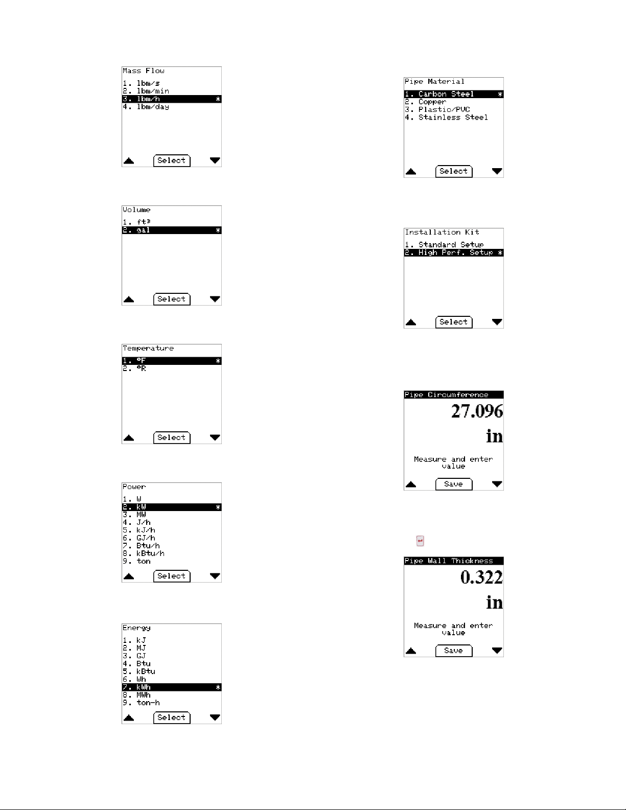
5. Mass Flow Unit Menu:
• This option determines how the mass ow is displayed.
• The Default is pounds-mass-per-hour.
6. Volume Unit Menu:
• This option determines how the totalized ow is displayed.
• The Default is Gallons.
7. Temperature Menu:
• This option determines how the temperature is displayed.
• The Default is degrees Fahrenheit.
Pipe Conguration Wizard
1. Pipe Material Menu:
• This option helps determine the pipe dimensions as well as account for
different material properties.
• The Default is Carbon Steel.
2. Install Kit Menu (High Performance):
• This option determines how the pipe dimensions will be collected.
• If a high accuracy meter was purchased, then the High Performance
Setup must be used to ensure correctness.
• Default: High Performance Setup.
a. Pipe Circumference Menu (High Performance):
• This value is the outside circumference of the pipe where the meter
is installed.
• The circumference can be measured with the tape included in the high
performance installation kit.
• Default: 27.096in (~8in diameter)
8. Power Menu:
• This option determines how the power is displayed.
• The Default is kilowatts.
9. Energy Menu:
• This option determines how the energy is displayed.
• The Default is kilowatt hour.
b. Wall Thickness Menu (High Performance):
• This value is the pipe wall thickness at the point at the point where the
meter is installed.
• The thickness can be measured with the UTG gauge included in the
high performance installation kit.
• Default: 0.322in
29
Page 30

3. Install Kit Menu (Standard):
A. Nominal Pipe Size Menu
• Select the diameter of the installation pipe from the list of standard pipe
diameters. If your nominal diameter is not listed or you have actual OD
data, select Other and enter the pipe diameter directly.
• Default: 8 in
6. Liquid Type Menu:
• This option species the process liquid to be measured.
• If Ethylene Glycol is selected, the next menu will allow the concentration to
be entered.
• Default: Water
B. Pipe Wall Thickness Menu:
• Select the wall thickness of the installation pipe from the list of standard
pipe wall thicknesses.
• If your wall thickness is not listed, select Other and enter the pipe wall
thickness directly.
• The options available depend on the pipe material selected.
• Default: Varies with selected pipe material.
4. Pipe Insertion Depth Display:
• This screen shows the calculated insertion depth based on the values
previously entered.
• Using the installation alignment kit provided with the IEFB, set the depth
to the value displayed on the alignment scale:
7. Pipe Conguration Summary Display: High Performance:
• This screen shows a summary of the settings entered in the pipe
conguration wizard when the high performance set up is used.
8. Continue to Energy Meter Conguration Wizard Question:
• If Continue is selected, the next menu displayed will be in the Energy Meter
Conguration Wizard.
• If Save & Exit is selected, the settings and values entered during the Pipe
conguration wizard will be stored and put into effect.
• Regardless of the selection, the ENTER button must be pressed to show
process data.
• Default: Continue
30
Page 31

T
ΔT
-ΔT +ΔT
9. Energy Meter Conguration Wizard
A. Flow Meter Location Menu:
◦Select the location of the ow meter in the inlet or outlet pipe.
◦Default: Inlet.
B. RTD Location Mapping Menu:
◦Select the location of each RTD in the inlet and outlet pipe.
◦Default: RTD 1=Inlet, RTD 2=Outlet.
C. Heating Crossover Temperature Menu:
◦Input the crossover temperature.
◦Default: 77°F.
D. Process Pressure Menu:
◦Input the process pressure inside the pipe.
◦Default: 232.060 PSI.
E. Energy Meter Summary Display:
◦This screen shows a summary of the settings entered in the Energy
Meter conguration wizard.
10. Analog Conguration Wizard:
• Analog Output Setup Menu:
• This option determines the type of analog output from the meter.
• Default: Current 4-20 mA
T
c o
Cooling
KEY
No energy recording
Heating Ti > Tco & Ti > To & ΔT > ΔTco
Cooling Ti < Tco & Ti < To & ΔT < ΔTco
i
0
c oΔTc o
Heating
11. Process Variable Menu:
• This option determines which variable is output on the analog signal.
• Default: Velocity
T
c o
Tco = Cross over Temp = 25°C Default
ΔTco = Cross over Delta Temp = 0.5 K
Ti = Inlet Temp
To = Outlet Temp
ΔT = Ti - To
31
Page 32

12. Analog Output High Menu:
• This value determines the process value at which the analog output will be
at maximum (e.g. 20 mA, 10 V, 5 V).
• Default: 20.0 ft/s.
2. Pulse/Frequency Output Menu:
• This option determines the type of digital output from the meter.
• Default: Disabled.
13. Analog Output Low Menu:
• This value determines the process value at which the analog output will be
at minimum (e.g. 4mA, 0V).
• Default: 0.0 ft/s
14. Analog Conguration Summary Display:
• This screen shows a summary of the settings entered in the Analog
conguration wizard.
Pulse/Frequency Wizard:
1. Continue to Pulse/Frequency Conguration Wizard Question:
• If Continue is selected, the next menu displayed will be in the Pulse/
Frequency conguration wizard.
• If Save & Exit is selected, the settings and values entered during the Analog
conguration wizard will be stored and put into effect.
• Regardless of the selection, the ENTER button must be pressed to
show process data.
• Default: Continue.
3. Pulse Variable Menu:
• This option determines the output pulse variable.
• Default: Total Flow.
4. Digital Output: Pulse
A. Pulse Scale Menu:
◦ This value determines the amount to totalized volume between each
pulse of the output.
◦ Default: 7 gallons/pulse.
B. Pulse Width Menu:
◦ This value determines the duration of the pulse when active.
◦ Default: 150 milliseconds.
C. Pulse/Frequency Summary Display:
◦ This screen shows a summary of the pulse settings entered in the
Pulse/Frequency conguration wizard.
32
Page 33

D. Frequency Output High Menu:
◦ This value determines the process value at which the frequency output
will be at maximum (500Hz).
◦ Default: 20.0 ft/s.
5. Empty Alarm Setup Menu
• This screen displays a summary of the Alarm output conguration. The
image displayed indicates the alarm type is Empty Pipe, meaning that
when an empty pipe condition is detected, the alarm contact will close.
E . Frequency Output Low Menu:
◦ This value determines the process value at which the frequency output
will be at minimum (0Hz).
◦ Default: 0.0 ft/s.
5. Pulse/Frequency Summary Display:
• This screen shows a summary of the frequency settings entered in the
Pulse/Frequency conguration wizard.
Alarm Wizard
1. If Continue is selected, the next menu displayed will be in the Alarm
conguration wizard.
2. If Save & Exit is selected, the settings and values entered during the Pulse/
Frequency conguration wizard will be stored and put into effect. Then, the
display will show process data.
3. Regardless of selection, the ENTER button must be used to choose either
option.
• Default: Continue.
Velocity Alarm - Outputs:
1. Alarm Type Menu:
• This option determines how the process velocity is compared to the trigger
value. Select either low or high limit.
• Default: Low Limit.
2. Alarm Trigger Menu:
• This value species the velocity at which the alarm is active or inactive.
• Default: 0.1 ft/s.
3. Alarm Hysteresis Menu:
• This value denes a range around the trigger value to prevent excessive
switching of the alarm output.
• Default: 0.1 ft/s.
4. Alarm Output Setup Menu:
• This option determines the type of alarm output.
• Default: Empty Pipe Alarm.
4. Alarm Output Summary Display:
• This screen shows a summary of the settings entered in the Alarm
conguration wizard when velocity alarm is selected.
33
Page 34

Communication Conguration Wizard
1. If Continue is selected, the next menu displayed will be the Communication
conguration wizard.
2. If Save & Exit is selected, the settings and values entered during the Alarm
conguration wizard will be stored and put into effect.
3. Regardless of the selection, the ENTER button must be pressed to show
process data.
• Default: Continue.
4. Select Protocol Menu:
• This option determines the protocol used by the meter over the RS-485
interface.
• Default: Disabled.
5. Network Address Menu:
• This value sets the device address on the RS-485 bus. Address range
depends on protocol; BACnet Communications Protocol (0-127), Modbus
• Default: 127
Communications Protocol (1-247)
7. Serial Parity Menu (Modbus® Communications Protocol Only):
• This option sets the serial parity on the RS-485 bus.
• Default: Even.
8. Serial Stopbits (Modus® Communications Protocol Only):
• The option sets the serial Stopbits on the RS-485 bus.
• Default: 1.
®
9. Communication Summary Display:
• This screen shows a summary of the settings entered in the Communication
conguration wizard.
6. Baud Rate Menu:
• This option selects the communication speed of the RS-485 bus.
• Default: 19200 (Modbus® Communications Protocol), 38400 (BACnet
Communications Protocol)
• After the Communication Wizard is complete, the meter setup is complete.
• The display will show Setup Complete and transition to display process
Data.
34
Page 35

Process Value Display:
• This display is the default view after power on of a congured meter or when the
Save & Exit option is selected from the Setup Wizard.
• Use the LEFT and RIGHT buttons to toggle between Flow/Velocity, Total
Flow, Inlet/Outlet Temperature, Delta Temperature/Power, and Power/Energy
views.
• Use the MENU or ENTER button to go to the main menu.
Device Information
• A list of all setting summaries. Use RIGHT and LEFT to move between
the various summary pages.
MAIN MENU
1. Language: Change the language of the display
2. Units: Change the display units
3. Pipe Setup: Enter the Pipe setup wizard
4. Energy Meter Setup: Enter the Energy Meter wizard
5. Analog Output Setup: Enter the Analog Output wizard
6. Pulse/Frequency Output Setup: Enter the Pulse/Frequency wizard
7. Alarm Output Setup: Enter the Alarm Output wizard
8. Communication Setup: Enter the Communication wizard
9. Save Setup File: Save the current setup to a le
10. Device Information: Show the summary displays from each wizard and
other meter/display information
11. Reset Flow Total: Reset totalized ow value
12. Reset Energy Statistic: Reset stored energy statistic
13. Damping: Sets the amount that velocity is averaged.
14. Calibration Factor: Congure custom velocity multiplier
15. Date & Time Setup: Change the date and time
16. Indicator Display Setup: Set up the indicator display
17. Save Defaults: Save the current settings as the user default values
18. Restore Defaults: Restore the previously saved user settings
35
Page 36

Date & Time Setup:
1. This menu sets up the date and time on the IEFB.
• Select Time Format to set time.
2. Set Time Format:
• This option selects 12 or 24 hour time format.
• Default: 12 hour.
3. Set Daylight Savings:
•. This option sets daylight savings time as active or inactive.
• Default: Inactive.
5. Set Local Time:
•. This option sets the local time in HH:MM:SS format.
• Use the up/down arrow keys to input the hours, minutes, seconds, and
AM/PM (12 hour format).
Save Setup File
• Create a setup le containing all the options and values selected from the
wizards. This le is stored in the display and can be retrieved by connecting a
USB cable (not included).
4. Set Date:
• This option sets the date in YYYY/MM/DD format.
• Use the up/down arrow keys to input the year, month, and day.
Reset Total Flow
• This menu allows the totalized ow value to be reset.
Reset Energy Statistics
• This menu allows the energy statistics to be reset.
36
Page 37

Damping
KEYPAD LOCKOUT SWITCH
• This value determines the amount of time the velocity is averaged. The
display value will reach 99% of the measured value within this time.
• Default: 30 s.
Indicator Display Setup
• If a remote indicator display is being used, select which values should be
displayed.
• Default: V. Flow & Velocity
Calibration Factor
• This value sets a custom multiplier of the measured velocity.
• Default: 1.000.
Save Defaults
• This menu saves the current conguration as the user default values. This
provides a means to save a known good conguration before making other
changes.
• Default: Yes.
Reset to Factory Default
This special menu is accessed by press & holding ENTER and MENU
buttons on the Device Information screen above. Answering Yes will reset all
selections and values to factory default values.
NOTICE
Key Pad Lockout Feature
• In units with the LCD option, a switch (shown in Figure 25) is located on
the display board that locks out the keypad to prevent undesired key presses
that could potentially change the meter conguration. When the switch is in the
“locked” position, the display will generate a padlock symbol in the lower right
corner as shown below.
• Default: Unlocked.
All BACnet Communications settings will be reset as well, including
the values that can only be set via BACnet Communications.
Restore Defaults
• This menu restores the saved user conguration to the current conguration.
This provides a means to restore the meter to a known working state.
• Default: No.
Figure 25: Keypad lockout switch
37
Page 38

Troubleshooting Guide
A status blink code is conveyed by the blinking of the status LED (Figure 26) using
the following parameters.
A blink is dened as the LED is ON for 200ms followed by the LED being OFF for
200ms.
If a status code has a tens digit, the tens digit blink code is created and then
followed by a 750ms delay OFF time. Then the ones digit blink code is created.
After a blink code is displayed, there is an OFF time of 2 sec before the blink code
is displayed again.
If more than one condition is true, the condition with the highest code will be
displayed.
Example: Item 3, Invalid Factory Conguration with a blink code of 11.
There would be a state of the LED being ON for 200 msec, then OFF for 200 msec,
then OFF for 750 msec, then ON for 200 msec, then OFF for 200 msec followed by
off for 2 sec before repeating this sequence.
Status
Item Condition
1
Invalid value
2
Empty pipe
3
Invalid factory conguration
4
NV access failed
5
NV write failed
6
Wiring board not installed
7
Flyback board not installed
8
Analog front end board not installed
9
Coil driver board not installed
10
Process temperature fault
11
Factory variable unlocked
12
Failure to measure process
13
Communication failure
14
Communication failure
15
Communication failure
16
Settings not saved
17
Settings not saved
18
Settings not saved
19
Settings not saved
20
Settings not saved
21
Meter not congured
22
Temperature is outside range of
expected value
23
One or both of the RTD paths are
open
24
One or both of the RTD paths are
shorted
LED Blink
Code Description Corrective Action
1
2
11
12
13
21
22
24
25
26
33
n/a
n/a
n/a
n/a
n/a
n/a
n/a
n/a
n/a
n/a
n/a
n/a
n/a
Invalid calibration (Value display on LCD)
The probe is not submerged in the process uid
The factory non-volatile conguration is invalid
The meter failed to read its non-volatile memory
The meter failed to write its non-volatile memory
The wiring board was not detected
The Flyback board was not detected
The Analog Front End board was not detected
The Coil Driver board was not detected
Temperature sensor not responding
The factory variables are unlocked and can be modied
Critical Error! Failed to measure process. (On-screen only)
Communication with the meter has failed. Settings not saved to
meter (On-screen only)
Communication with meter has failed. Attempting to re-establish.
Please wait … (On-screen only)
Critical Error! Failed to access settings in non-volatile storage.
(On-screen only)
Error: File Not Saved! Access Denied (On-screen only)
Error: File Not Saved! Storage Media Timeout (On-screen only)
Error: File Not Saved! Storage Media Not Ready (On-screen
only)
Error: File Not Saved! Storage Media Not Found (On-screen
only)
Error: File Not Saved! Unknown (On-screen only)
Meter not congured! The meter must be congured with a setup
display before an indicator display can be used.
Screen shows inlet and outlet temperatures as RANGE.
Screen shows inlet and outlet temperatures as OPEN.
Screen shows inlet and outlet temperatures as SHORT.
STATUS LED
Figure 26: LED status blink
Return to factory, calibration required
Ensure the pipe is properly lled, ensure proper
installation depth
Return to factory, conguration and calibration
required
Return to factory for repair
Return to factory for repair
Return to factory for repair
Return to factory for repair
Return to factory for repair
Return to factory for repair
Return to factory for repair
Power cycle, reset, or send lock command to
meter
Power cycle, reset via BACnet/Modbus
Disconnect and reconnect display
Disconnect and reconnect display
Power cycle, reset via BACnet/Modbus®,
consult factory
Disconnect and reconnect display,
replace SD card on display PCBA
Disconnect and reconnect display,
replace SD card on display PCBA
Disconnect and reconnect display,
replace SD card on display PCBA
Verify SD card is fully inserted into SD card
socket on display PCBA
Disconnect and reconnect display,
replace SD card on display PCBA
Congure setup display before connecting
indicator display.
Reset temperature values input or check
process
Return to factory for repair
Return to factory for repair
®
Item 1 Display Item 10 Display
Item 14 Display Item 15 Display
Item 12 Display Item 13 Display
Item 16 Display Item 17 Display
38
Page 39

Item 18 Display Item 19 Display
Item 20 Display
Flow Condition Warnings:
If a reverse ow condition exists, an “R” with an exclamation mark in a triangle will
appear as shown below:
If an empty pipe condition exists, an “E” with an exclamation mark in a triangle will
appear as shown below:
If velocity alarm condition exists a “V” with an exclamation mark in a triangle will
appear as shown below:
Item 21 Display
Item 22 Display Item 23 Display
Item 24 Display
MAINTENANCE/REPAIR
Upon nal installation of the Series IEFB, no routine maintenance is required. If
recalibration is desired the unit must be returned to Dwyer Instruments, Inc. to be
calibrated. Contact customer service to receive a Return Goods Authorization
number before shipping you product back for calibration. The Series IEFB is not eld
serviceable and should be returned if repair is needed. Field repair should not be
attempted and may void the warranty.
WARRANTY/RETURN
Refer to “Terms and Conditions of Sale” in our catalog or on our website. Contact
customer service to receive a Return Goods Authorization number before shipping
your product back for repair. Be sure to include a brief description of the problem plus
any relevant application notes.
This product uses FreeRTOS (www.FreeRTOS.org) version 9.0.0.
A copy of the original FreeRTOS source shall be provided upon request.
39
Page 40

NOTES
__________________________________________________________________________________________________________________________________________
__________________________________________________________________________________________________________________________________________
__________________________________________________________________________________________________________________________________________
__________________________________________________________________________________________________________________________________________
__________________________________________________________________________________________________________________________________________
__________________________________________________________________________________________________________________________________________
__________________________________________________________________________________________________________________________________________
__________________________________________________________________________________________________________________________________________
__________________________________________________________________________________________________________________________________________
__________________________________________________________________________________________________________________________________________
__________________________________________________________________________________________________________________________________________
__________________________________________________________________________________________________________________________________________
__________________________________________________________________________________________________________________________________________
__________________________________________________________________________________________________________________________________________
__________________________________________________________________________________________________________________________________________
__________________________________________________________________________________________________________________________________________
__________________________________________________________________________________________________________________________________________
__________________________________________________________________________________________________________________________________________
__________________________________________________________________________________________________________________________________________
__________________________________________________________________________________________________________________________________________
__________________________________________________________________________________________________________________________________________
__________________________________________________________________________________________________________________________________________
__________________________________________________________________________________________________________________________________________
__________________________________________________________________________________________________________________________________________
__________________________________________________________________________________________________________________________________________
__________________________________________________________________________________________________________________________________________
Printed in U.S.A. 8/19 FR# 444531-00©Copyright 2019 Dwyer Instruments, Inc.
DWYER INSTRUMENTS, INC.
P.O. BOX 373 • MICHIGAN CITY, INDIANA 46360, U.S.A.
40
Phone: 219/879-8000
Fax: 219/872-9057
www.dwyer-inst.com
e-mail: info@dwyermail.com
 Loading...