

Dwyer Instruments HT Series, HT00 Series, HT10 Series, HT01, HT11 Operating Instructions Manual
Page 1
BULLETIN E-90-HT
SERIES HT RH/Temperature Transmitter
Specifications – Installation and Operating Instructions
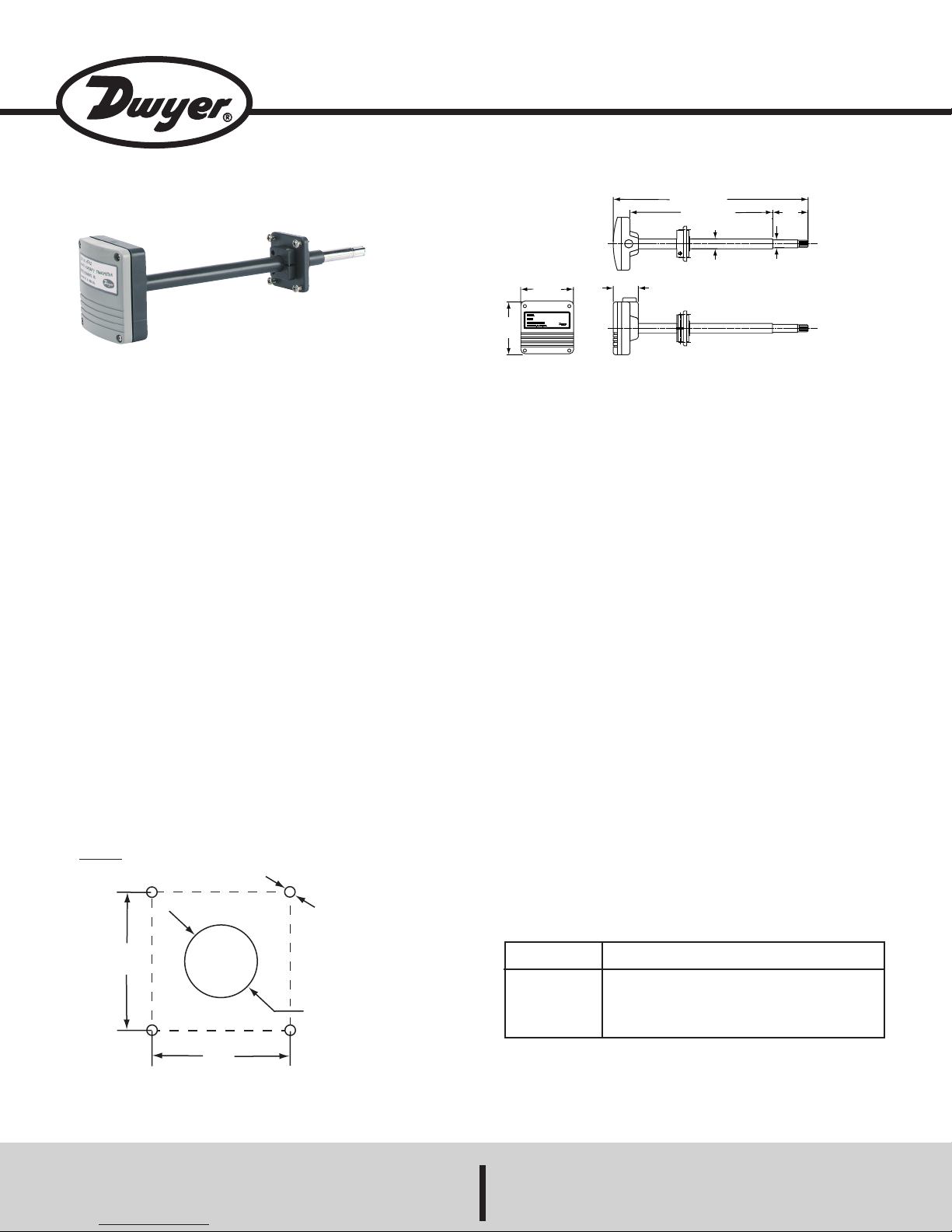
*Duct Mount unit shown.
DESCRIPTION
Monitor and control relative humidity and temperature in
building energy management systems with the Series HT
Humidity Temperature Transmitter. Designed for demanding
HVAC/EMCS applications, the Series HT provides ±3% RH
accuracy and ±1% stability per year. Routine calibration is
not required with the fully interchangeable sensor. Two-wire
connections allow easy installation directly into air ducts or
within a controlled area.
INSTALLATION
Mounting
The duct mount models must be mounted as described
below:
1. Drill four 1/8 (3.2 mm) diameter holes for the mounting
screws in the locations shown in Figure 1.
2. Cut a 0.866 (22 mm) diameter hole in the duct for the
sensor in the location shown in Figure 1.
3. Attach the duct mounting bracket to the duct with the
four screws provided.
4. Slide the sensor/transmitter assembly through the
center hole in the mounting bracket and secure into
place by tightening the screw located on the side of the
raised square portion of the mounting bracket.
Reminder: Remove the yellow sensor protection cap
befor
e installing the sensor into your duct.
3-5/32
[80.17]
3-5/32
[80.17]
11-5/8 [295.3]
1-1/2
[38.10]
8-1/2 [215.9]
19/32 DIA.
[15.09]
2-1/8
[53.98]
15/32 DIA.
[11.91]
PHYSICAL DATA
Relative Humidity Range: 10 to 90% RH.
Temperature Range: Duct mount: -40 to 140˚F (-40 to 60˚C), wall
mount: 23 to 131˚F (-5 to 55˚C).
Accuracy: ±3% RH @ 25˚C; ±0.3˚C @ 25˚C.
Stability: ±2% RH over 2 years.
RH Temperature Dependence: <±1.5% RH from 14 to 140˚ (-10
to 60˚C).
Temperature Dependence: 0.01˚C/˚C.
Temperature Sensor: Pt 1000Ω RTD.
Response Time: 15 seconds.
Output Signal: 4 to 20 mA.
Supply Voltage: 10 to 28 VDC.
Current Consumption: 4 mA minimum.
Operating Humidity Range: Duct mount: 0 to 100%, wall mount:
0 to 90%.
Operating Temperature Range: Duct mount: 14 to 140˚F (-10 to
60˚C), wall mount: 23 to 131˚F (-5 to 55˚C).
Storage Temperature Range: -40 to 140˚F (-40 to 60˚C).
Conduit Connection:
Mounting Connection:
Housing Material: ABS plastic.
Enclosure: Duct mount only/IP65.
Weight: 0.6 lb (0.3 kg).
1
/2 NPT.
3
/4 NPT.
Ø.125 [3.2]
Tapping Screw
1.65
DIN 7981
[42]
Ø 0.866 [22] min
1.65
[42]
FIGURE 1: Drilling Dimensions for Duct Mount Units
DWYER INSTRUMENTS, INC.
P.O. BOX 373 • MICHIGAN CITY, INDIANA 46361, ,U.S.A. Fax: 219/872-9057 e-mail: info@dwyer-inst.com
SERIES HT RH/TEMPERATURE TRANSMITTERS
Model
Number
HT00* Humidity Transmitter, wall mount
HT01 Humidity Transmitter, duct mount
HT10* Humidity/Temp Transmitter, wall mount
HT11 Humidity/Temp Transmitter, duct mount
*Wall mount not shown
Description
Accessories
No. HT5, Replacement Humidity Sensor
No. HT6, Replacement Pt1000Ω RTD
Phone: 219/879-8000 www.dwyer-inst.com
Lit-By Fax: 888/891-4963
Page 2
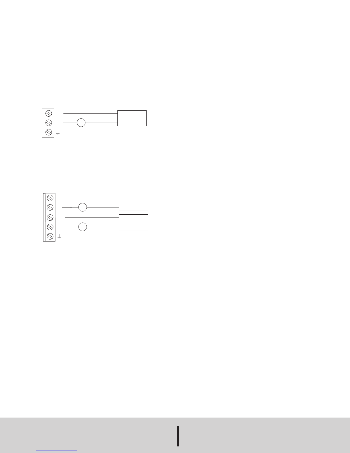
Electrical Connections
The Series HT RH/Humidity Transmitter is a true 2-wire, 420 mA current output device. Electrical connections are
made to screw terminals located beneath the light gray
front casing. For duct mount units, remove the 4 screws
located on the front face of the housing. For wall mount
units, gently unsnap the light gray front casing from the
back portion of the housing.
Wire the humidity transmitters models HT00 and HT01 as
shown in Figure 2.
3
2
+RH
-RH
4-20mA
mA
+
POWER
SUPPLY
10...28VDC
-
1
Figure 2: Wiring Diagram for HT00 & HT01
Wire the humidity and temperature transmitters models
HT01 and HT11 as shown in Figure 3.
5
4
3
2
+T
-T
+RH
-RH
4-20mA
mA
4-20mA
mA
+
POWER
SUPPLY
10...28VDC
-
+
POWER
SUPPLY
10...28VDC
-
1
REPLACEMENT SENSORS
Series HT Temperature/Humidity Transmitters incorporate
fully interchangeable humidity and temperature sensors.
These transmitters do not require recalibration when the
sensor is changed.
In duct mount models, the sensors are located beneath the
filter membrane in the tip of the duct probe. Simply
unscrew the filter membrane and remove the sensor.
In wall mount models, the sensors are located on the circuit
board. Gently unsnap the light gray front casing from the
back portion of the housing and replace the sensor.
MAINTENANCE/REPAIR
No routine maintenance is required on the Series HT
RH/Temperature Transmitter. These units are not field
repairable and should be returned to the factory if service is
required. After first obtaining a Returned Goods
Authorization (RGA) number, send the unit, freight prepaid
to the following address. Please include a clear description
of the problem plus any application information available.
Dwyer Instruments, INC.
Attn: Repair Department
102 Indiana Highway 212
Michigan City, IN 46360
Figure 3: Wiring Diagram for HT10 & HT11
Installing the Cable Seal (Duct mount units only)
Included with the duct mount models HT01 and HT11 is a
rubber cable seal. This seal helps provide a dust and water
tight housing and ensures environmental protection per
IP65. Install the cable seal as described below:
1. Press the rubber seal into the conduit hole located on
the side of the housing.
2. Pierce the center of the seal with a cable or a
screwdriver.
3. Pull the cable through the hole in the center of the seal.
Designed for cable diameters 7...10 mm.
©Copyright 2000 Dwyer instruments, Inc Printed in U.S.A. 4/00
DWYER INSTRUMENTS, INC.
P.O. BOX 373 • MICHIGAN CITY, INDIANA 46361, ,U.S.A. Fax: 219/872-9057 e-mail: info@dwyer-inst.com
Phone: 219/879-8000 www.dwyer-inst.com
Lit-By Fax: 888/891-4963
 Loading...