

Dwyer Instruments HFPC Series, HFPS Series Specifications-installation And Operating Instructions
Page 1
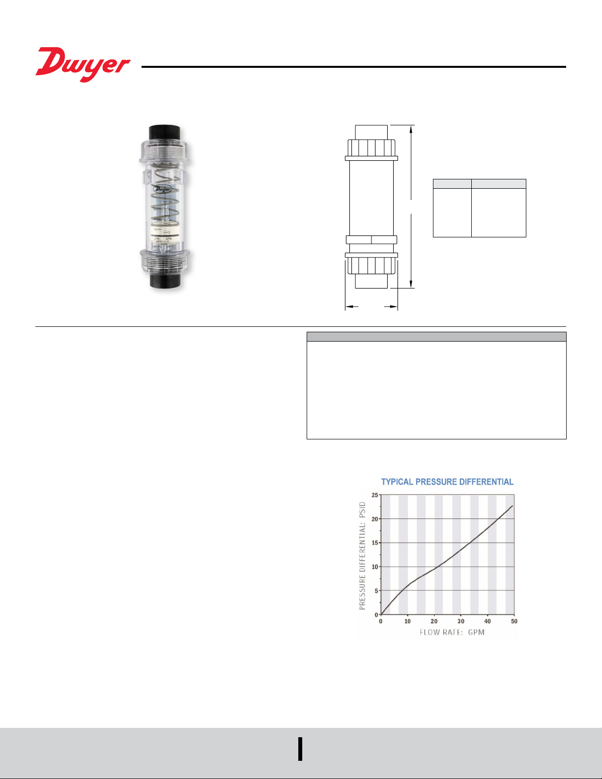
Series HFPC & HFPS Plastic Flow Meters
[61.91]
®
Specications - Installation and Operating Instructions
Meter Size Dim “L”
1/2 male
1/2 female
“L”
3/4 male
3/4 female
1 male
1 female
ø2-7/16
Bulletin F-71
7-11/16 [195.26]
7-5/32 [181.76]
8-1/32 [204.00]
7-9/16 [192.09]
8-3/32 [205.58]
7-9/16 [192.09]
The HFPC & HFPS SERIES Flowmeters are made of injection molded, polycarbonate
and polysulfone bodies. Series HFPC and HFPS owmeters have dual scales
measuring in both GPM and LPM with ±5% full scale accuracy. Models are available
with 1/2˝, 3/4˝ or 1˝ male or female NPT connections. Female 1/2˝, 3/4˝ and 1˝ BSPP
connections are also available. Rugged construction allows these meters to handle
maximum pressures of 325 psig and 200 F. Units can be mounted in any position, even
applications with downward ow.
CAUTION: Series HFPC & HFPS Flowmeters are for indoor use only or areas
without direct sunlight. Polycarbonate & polysulfone are adversely affected by
ultraviolet light.
INSTALLATION
The casing and union retainers are made of either Polycarbonate or Polysulfone
materials permitting use with a variety of media. Use of mild detergent to clean the
meter body is encouraged to prevent damaging the label or associated components.
The meters are mounted in-line and are direct reading. The meters can be mounted
in a vertical or horizontal position as long as the uid is owing in the direction of
the arrow on the ow scale. No straight pipe is required before or after the meter. In
fact, 90° elbows can be installed on both ends without any noticeable ow variation.
When installing a meter, apply “Plumbers Tape” or “Liquid Plumber’s Sealant” on pipe
threads. If tape is used, be sure to leave 1/8˝ (3 mm) of pipe thread exposed on end
of pipe. Position lter in front of meter and in a location that allows easy access for
routine maintenance.
The meter should not be mounted in a manner such that piping misalignment or other
system components can exert force or produce a bending moment on the pressure
vessel.
To retain accuracy and repeatability internal moving parts are closely toleranced and
require ltration of at least 74 micron or a 200 mesh screen.
When installing meters onto threaded pipe caution should be taken not to over tighten
the pipe connections or introduce torque on the main body of the meter. The meter
main body may rupture if over-tightened.
SPECIFICATIONS
Service: Compatible liquids.
Wetted Materials: HFPC: Polycarbonate body, Buna-N seals, Stainless Steel
spring, Polysulfone connections. HFPS: Polysulfone body, Buna-N seals, Stainless
Steel spring, Polysulfone connections.
Maximum Pressure: 325 psig (22.4 bar).
Maximum Temperature: HFPC: 200° F (93° C) HFPS: 250° F (121° C).
Accuracy: ±2% FS.
Repeatability: ±1% FS.
Pressure Loss: See chart.
Weight: Standard models 1 lb (453.6 g). Models with optional brass connections 2
lb (907 g).
DWYER INSTRUMENTS, INC.
P.O. BOX 373 • MICHIGAN CITY, INDIANA 46360, U.S.A.
Phone: 219/879-8000
Fax: 219/872-9057
www.dwyer-inst.com
e-mail: info@dwyermail.com
Page 2
INSTALLATION DOS AND DON’TS
To obtain satisfactory operation from a HFPC & HFPS meters, the following points
should be considered:
DO:
• Install a pressure gauge near the inlet of the meter
• Place throttling valves at the outlet of the meter
• Use pipe sealer on the connections
• Install solenoid valves at meter outlet (as far downstream as possible)
• Mount in any orientation: vertical, horizontal or upside down
DO NOT:
• Place restrictions between the meter’s pressure gauge meter inlet
• Use in systems where reverse ow is possible
• Place meter in non-aligned piping
• Over-ow the meter by more than 150% of maximum reading
• Operate at pressures and temperatures greater than specied
• Be mounted near hot pipes or equipment which can cause damage to the pressure
vessel
• Use in systems where the assembled piping is not supported. Externally applied
piping forces may cause the meter to rupture or malfunction.
OPERATION
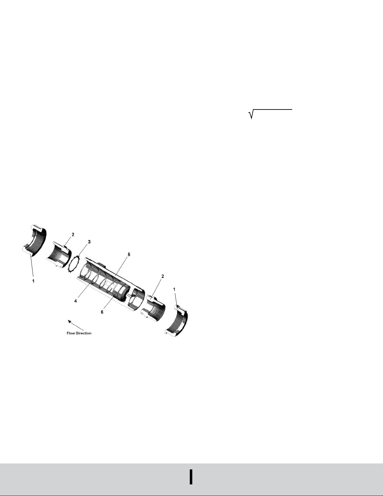
The meters are tubular, with all internal wetted parts sealed within the body casing
(5). Running through the center of the body casing is a tapered center shaft which is
centered in the bore. Encircling the shaft is a sharp-edged, oating metering poppet
(6). The metering poppet is held in the “no ow” position by the biased return spring
(4). As the ow moves through the meter it creates a pressure differential across the
oating orice disk, forcing the disk and transfer magnet against the return spring. As
ow increases, the pressure differential across the metering poppet increases, forcing
poppet to move along the tapered center shaft. As ow decreases, the biased return
spring forces the poppet down the tapered center shaft, returning to the “no ow”
position.
Reading the Meter
Notice the black reference line which runs 360° around the metering poppet. This
reference line moves under the scale in direct relation to the movement of the poppet.
When uid is owing, the ow rate through the meter is read by lining up the black
reference line with the closest rate line on the ow scale.
Specic Gravity or Density Effect
Standard meters are calibrated for WATER with a specic gravity of 1.0. The oating
disk meter is affected by uid density as are most other similar type meters. HFPC &
HFPS meters have less of this effect because of the sharpness of the oating orice
disks being used. The indicated ow reading will read high for heavier uids and low
for lighter uids. A corrective factor can be applied to the standard scale or a special
scale can be added at additional costs. When measuring uids with other specic
gravities, the basic equation below can be used to develop corrected readings.
For WATER Meters use: 1.0/Specic Gravity x scale reading
CONTAMINATION AND FILTRATION
Recommended Filtration
System ltration of at least a 74 micron lter or a 200 mesh screen is recommended. It
has been found that if inadequate ltration has caused meter failure, it will normally fail
in the open position. Some systems may require a magnetic lter. IMPORTANT: Meter
damage caused by excessive contamination is not covered under warranty.
Stabilized Contamination
The goal of ltration is to create effective protection from system contamination.
Proper ltration stabilizes contamination to allow uid components to function properly.
A uid system is considered stabilized when, “contamination in” equals “contamination
out”. Proper ltration must reduce initial contamination to a stabilized level within an
acceptable time period. The system should be stabilized in time to prevent premature
wear or damage to meter components.
Figure 1 (Flow Meter Cross Section)
MAINTENANCE
Upon nal installation of the Series HFPC and HFPS Plastic Flow Meters, no routine
maintenance is required. A periodic check of the system calibration is recommended.
The Series HFPC and HFPS is not eld serviceable and should be returned if repair
is needed (eld repair should not be attempted and may void warranty). Be sure to
include a brief description of the problem plus any relevant application notes. Contact
customer service to receive a return goods authorization number before shipping.
©Copyright 2016 Dwyer Instruments, Inc. Printed in U.S.A. 8/16 FR# 443560-00 Rev. 1
DWYER INSTRUMENTS, INC.
P.O. BOX 373 • MICHIGAN CITY, INDIANA 46360, U.S.A.
Phone: 219/879-8000
Fax: 219/872-9057
www.dwyer-inst.com
e-mail: info@dwyermail.com
 Loading...