


Dwyer Instruments HFL-2-05, HFA-0-01, HFA-1-12, HFA-1-22, HFL-4-25 Specifications-installation And Operating Instructions
...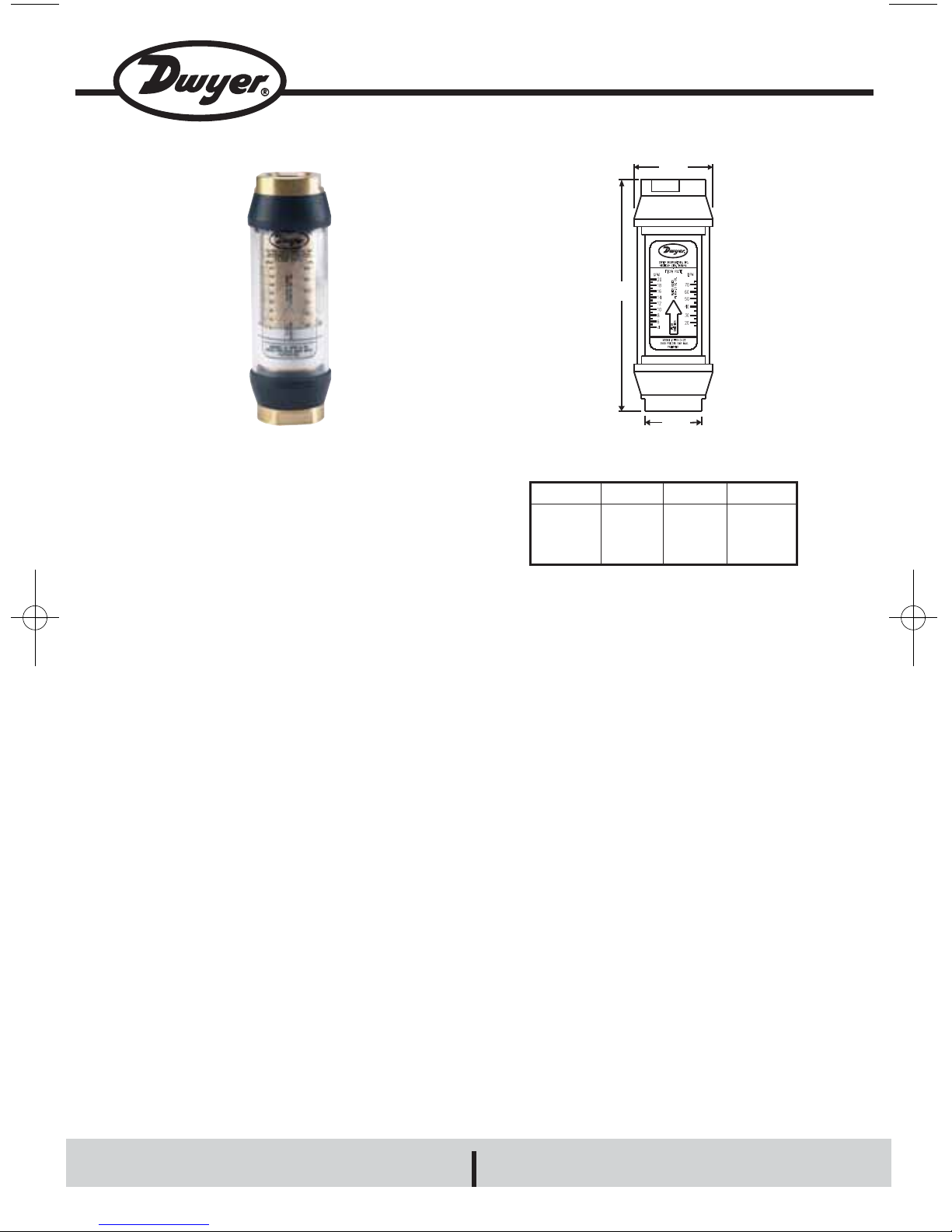
Valve
Size
1/8 NPT
1/4 to 1/2 NPT
3/4 to 1 NPT
1-1/4 to 1-1/2 NPT
2 NPT
Series HF IN-LINE FLOW MONITORS
Specifications - Installation and Operating Instructions
BULLETIN F-55
Series HF Flow Monitors combine the
simplicity of a sharp edged orifice disk with a
variable area flow monitor to provide a low cost
way to measure flow at high pressures. These
monitors are tubular, with all internal wetted parts
sealed within the body casing. Running through
the body is a tapered shaft which is centered in
the bore by pilot disks at each end. Surrounding
the shaft are a sharp-edged floating orifice disk,
a transfer magnet and return spring. The disk
and transfer magnet are held in the “no flow”
position by a biased return spring. As flow moves
through the monitor, it creates a differential
pressure at the orifice disk forcing the disk and
transfer magnet against the return spring. As
flow increases, the differential pressure at the
disk increases, forcing the disk and transfer
magnet to move along the tapered center shaft.
As flow decreases, the biased return spring
forces the disk and transfer magnet down the
center shaft, returning to the “no flow” position.
In metal casing monitors, disk and magnet
movement are not visible so a magnet follower is
located outside the body casing, magnetically
coupled to the internal transfer magnet. As flow
increases, motion of the internal magnet moves
the magnet follower outside the body casing,
under the scale.
SPECIFICA TIONS
Service: Compatible gases or liquids.
Wetted Materials: Body: Aluminum, brass or
304 SS; Seals: Buna-N or Fluoroelastomer;
Magnet: PTFE coated Alnico; Other internal parts:
304 SS.
Maximum Viscosity: 500 SSU.
Temperature Limits: HFA, HFL, HFB and HFS
Models: 240°F (116° C); HFH Models: 400°F
(204°C).
Pressure Limits: HFA Models: 600 psig (41 bar);
HFL, HFB and HFH Models: 3500 psig (240 bar);
HFS Models: 6000 psig (413 bar).
Accuracy: ±4% FS over entire range; ±2.5%
over center third of the measuring range.
Repeatability: ±1% of full scale.
Shipping Weight: 1/8 to 1/2˝ female NPT
Models; 2 lb (0.9 kg); 3/4 to 1˝ female NPT
Models: 3.5 lb (1.59 kg); 1-1/2˝ female NPT
Models: 11 lb (5 kg); 2˝ female NPT Models: 13.5
lb (6.12 kg).
("A")
("C")
("B")
“A”
Reference
1.25
1.875
2.375
3.500
3.500
“B”
Wrench Flats
0.875
1.250
1.750
2.250
2.250
“C”
Reference
4.813
6.562
7.125
10.125
12.625
DWYER INSTRUMENTS, INC.
Phone: 219/879-8000 www.dwyer-inst.com
P.O. BOX 373 • MICHIGAN CITY, IN 46361,U.S.A. Fax: 219/872-9057 e-mail: info@dwyer-inst.com
www.GlobalTestSupply.com
Find Quality Products Online at: sales@GlobalTestSupply.com

READING THE MONITOR
Note the red reference line running 360° around the
white magnet follower. This line moves in direct
proportion to the movement of the internal orifice
disk. When fluid is flowing, the flow rate is read by
aligning the red reference line with the closest scale
graduation.
SPECIFIC GRAVITY OR DENSITY EFFECT
Standard water monitors are calibrated with water
and oil monitors are calibrated with .873 S.G. oil.
Flow indication will read high for heavier fluids and
low for lighter fluids. A correction factor for other
specific gravities can be established using the
following formulas.
For Water Monitors use:
Actual = Observed Reading x 1.0
S.G.
For Oil Monitors use:
Actual = Observed Reading x 0.873
S.G.
VISCOSITY EFFECT
The Series HF Flow Monitor incorporates a unique
floating sharp-edged orifice disk which provides
greater operating stability and accuracy over wide
ranging viscosities up to 500 SSU.
√
304 Stainless Steel body for high-pressure fluids:
Wetted Parts: 304 SS, Fluoroelastomer and PTFE
Brass body for water based fluids (non-steam):
Wetted Parts: Brass, PTFE coated Alnico, 304 SS and Buna-N
Brass Body High Temperature 400˚F for water based fluids:
Wetted Parts: Brass, PTFE coated Alnico, 304 SS and Fluoroelastomer
Range, Air
SCFM
2-12
2-12
4-23
Connection
Size
1/8˝ female NPT
1/4˝ female NPT
1/4˝ female NPT
Model
Number
HFA-0-01
HFA-1-12
HFA-1-22
Model
Number
HFS-0-01
HFS-2-02
HFS-2-10
Connection
Size
1/8˝ female NPT
1/2˝ female NPT
1/2˝ female NPT
Range, GPM
Water
0.05-1
0.2-2
0.5-10
Range, LPM
Water
.19-3.8
.75-7.5
1-19
7.5-55
7.5-75
19-130
19-189
38-379
31-284
76-568
Connection
Size
1/8˝ female NPT
1/8˝ female NPT
1/2˝ female NPT
3/4˝ female NPT
3/4˝ female NPT
1˝ female NPT
1-1/2˝ female NPT
1-1/2˝ female NPT
2˝ female NPT
2˝ female NPT
Model
Number
HFB-0-01
HFB-0-02
HFB-2-05
HFB-3-15
HFB-3-20
HFB-4-35
HFB-5-50
HFB-5-100
HFB-6-75
HFB-6-150
Model
Number
HFH-2-05
HFH-2-10
HFH-4-35
Connection
Size
1/2˝ female NPT
1/2˝ female NPT
1˝ female NPT
Range, GPM
Water
0.5-5
1-10
5-35
Range, GPM
Oil
0.5-5
2-25
Connection
Size
1/2˝ female NPT
1˝ female NPT
Model
Number
HFL-2-05
HFL-4-25
Max. Pressure
Drop, PSID
3.32
3.32
3.61
Range, LPM
Oil
1-19
7.5-95
Max. Pressure
Drop, PSID
6.08
8.41
Aluminum body for oil based fluids:
Wetted Parts: Aluminum, PTFE coated Alnico, 304 SS and Buna-N
Range, GPM
Water
0.05-1
0.2-2
0.5-5
2-15
2-20
4-40
5-50
10-100
8-75
20-150
Max. Pressure
Drop, PSID
1.98
5.58
7.18
10.2
6.2
15.2
9.25
25.59
14.95
39.86
Range, LPM
Water
0.19-3.8
0.75-7.5
1.9-38
Max. Pressure
Drop, PSID
1.98
5.58
8.68
Range, LPM
Water
1-19
3.8-38
19-130
Max. Pressure
Drop, PSID
7.18
8.68
13.46
Aluminum body for air or other non-corrosive gases:
Wetted Parts: Aluminum, PTFE coated Alnico, 304 SS and Buna-N
√
www.GlobalTestSupply.com
Find Quality Products Online at: sales@GlobalTestSupply.com