

Page 1
Bulletin AQ-GSTC
3-23/64
®
Series GSTC Carbon Monoxide/Nitrogen Dioxide Gas Transmitter
Specications - Installation and Operating Instructions
Wall mount
with LCD
The Series GSTC Carbon Monoxide/Nitrogen Dioxide Gas Transmitter monitors
the gas concentration in underground parking garages and loading docks. The carbon
monoxide transmitter is used to measure the exhaust of gasoline engines, while the
nitrogen dioxide transmitter is used for diesel engines. The Series GSTC is compatible
with either BACnet or Modbus
to be used with almost any building management controller. The GSTC output is
communicated over an RS-485 wire via BACnet or Modbus
To maximize the accuracy of the Series GSTC, the sensor can be eld-calibrated using
the A-449 remote LCD display. When the sensor reaches the end of its life, the display
will indicate that the sensor needs to be replaced.
®
BACnet and Modbus
nodes in any segment to 32. Therefore, the transceiver may be rated at one unit load.
Fractional loads are also acceptable. The Series GSTC accounts as an eighth of a
load on the MSTP network.
WARNING
accordance with the job wiring diagram and in accordance with national and local
electrical codes. Use copper conductors only.
NOTICE
NOTICE
NOTICE
NOTICE
replacements will not be covered under warranty, but they can be revived by allowing
them to stabilize in an environment above 40% RH for 10 days. Once revived, they
need to be recalibrated before use.
INSTALLATION
NOTICE
• The transmitter should be mounted at normal breathing height, approximately 5 to 6
ft above the oor.
• The unit may be mounted in the horizontal or vertical position. It should be mounted
in an area that is shielded from direct contact with the elements or direct sunlight.
• Mount in an area that will prevent the sensor from having any direct contact with
water.
• The unit should be placed in an area that will give an average of the air quality. Do
not place the unit so it will receive direct engine exhaust. Prolonged exposure to
direct engine exhaust may damage the sensor.
communication protocol recommend limiting the number of
Disconnect power supply before installation to prevent electrical
shock and equipment damage. Make sure all connections are in
Use electrostatic discharge precautions (e.g., use of wrist straps)
during installation and wiring to prevent equipment damage.
Avoid locations where severe shock or vibration, excessive
moisture, or corrosive fumes are present.
Do not exceed ratings of this device, permanent damage not
covered by warranty may result.
The electrochemical sensors should be stored in an environment
with a minimum humidity level of 20% RH. If the sensor dries out,
These are general guidelines. Local laws or ordinances will take
precedence.
Wall mount
without LCD
®
communication protocol, allowing the transmitter
®
communication protocol.
Duct mount
3-45/64
[94.06]
3-1/8
[107.95]
4-17/32
[115.09]
5-7/64
[129.78]
SPECIFICATIONS
Sensor: Field replaceable electrochemical, 4 years typical lifespan.
Range: CO: 0 to 500 PPM, NO2: 10 PPM.
Output Drift: <5% per year in air.
Coverage Area: 5000 to 7500 sq ft typical.
Accuracy: CO: 2% FS, NO2: 3% FS, at the time of calibration.
Resolution: CO: 1 PPM; NO2: 0.1 PPM.
Temperature Limits: -4 to 122°F (-20 to 50°C).
Storage Temperature: For best sensor life, 32 to 68°F (0 to 20°C).
Humidity Limits: 15 to 90% RH constant; 0 to 99% RH intermittent.
Response Time: <45 s to 90% CO, <25 s to 90% NO2.
Span and Zero Adjustment: Via pushbutton, using optional A-449 display. Zero
only via BACnet or Modbus
Housing: UV resistant glass lled polycarbonate.
Output Signals: BACnet MS/TP or Modbus
communication protocol.
Power Requirements: 10 to 36 VDC or isolated 21.6 to 33 VAC.
Electrical Connection: Removable terminal block, knock outs for conduit tting.
Calibration: Via pushbuttons using A-449 auxiliary display. Span gas
concentration is eld selectable.
Enclosure Rating: IP64.
Weight: 1 lb (0.45 kg).
Agency Approvals: CE.
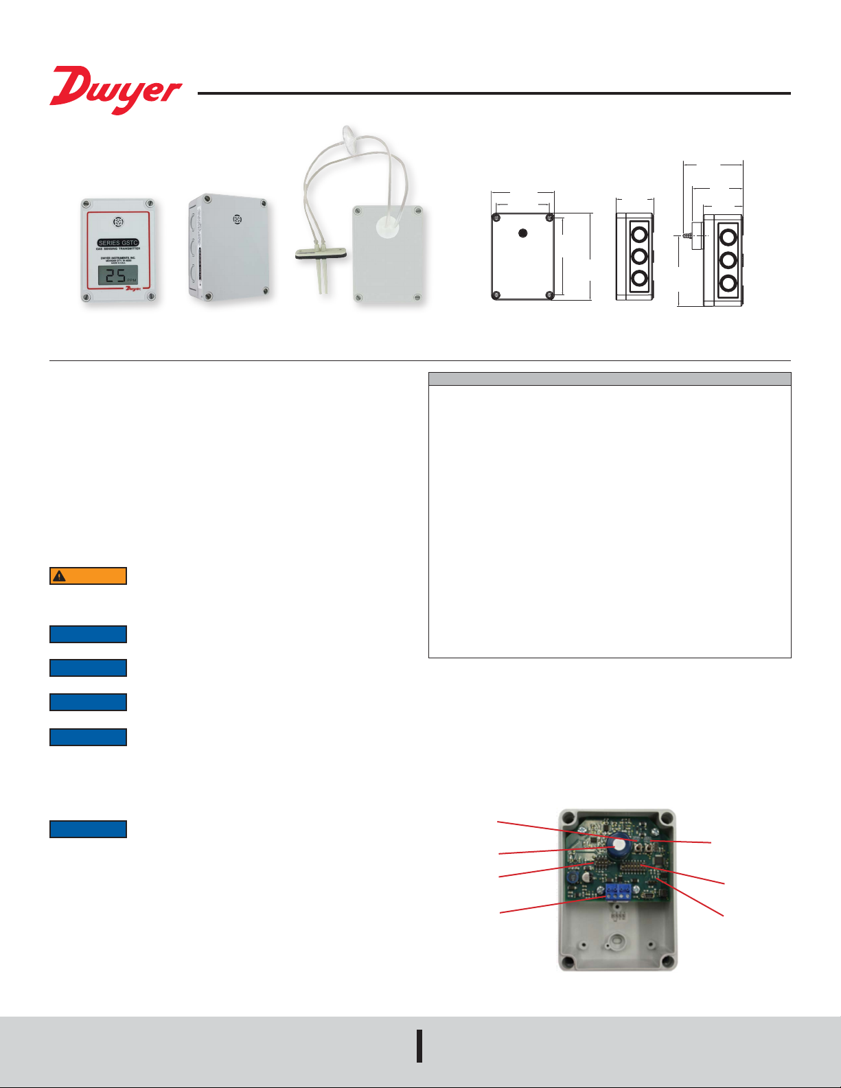
Figure 1 shows the location of the wiring terminal, 8 position DIP Switch SW1, used for
conguring the RS-485 address, the 4 position DIP Switch SW2, used for conguring
hardware and software options, sensor, span and zero adjustments, and status LEDs.
The device provides three LEDs to indicate status and activity. The LEDs are located to
the right of DIP Switch SW1. The yellow LED indicates that the unit is sending a BACnet
or Modbus
BACnet or Modbus
red LED will ash once periodically if the BACnet or Modbus
address is set incorrectly or the red LED will ash twice periodically if the auto serial
conguration is in progress.
®
communication protocol. The green LED indicates the unit is receiving a
Span
Sensor
DIP Switch
SW2
Wiring
Terminal
®
communication protocol.
®
communication protocol addressed to this specic device. The
2-15/64
[56.75]
Duct mountWall mount
®
RTU (switch selectable)
[85]
2-55/64
[73]
2-15/64
[57]
3-59/64
[100]
®
communication protocol
Zero
DIP Switch
SW1
Status
LEDs
DWYER INSTRUMENTS, INC.
P.O. BOX 373 • MICHIGAN CITY, INDIANA 46360, U.S.A.
Modbus® is a registered trademark of Schneider Automation, Inc.
Phone: 219/879-8000
Fax: 219/872-9057
Figure 1
www.dwyer-inst.com
e-mail: info@dwyermail.com
Page 2
Wall Mounting
TO
PWRCOM A(-)B(+)
TO
NEXT
PWRCOM A(-) B(+)
1. Remove the cover plugs from the face of the unit and the top cover.
2. Disconnect the display cable from the USB connector on the main circuit board (if
present).
3. Remove the desired conduit tting knock out and install conduit tting (not
provided).
4. Position the transmitter where it is to be mounted and mark the mounting holes in
each corner of the housing.
5. Drill or punch out marked locations.
6. Place the transmitter box over mounting holes on wall and align. Install wall mount
screws (not provided) in mounting holes.
7. Proceed with wiring diagrams according to Figures 3 and 4.
8. Set DIP Switches SW1 and SW2 as desired. Refer to Figure 5, Figure 6, and
Appendix I.
9. Reconnect the LCD cable to the USB port on the main circuit board (if present).
10. Replace cover and cover plugs on the face of the unit.
CO:
Locate GSTC carbon monoxide transmitter about 5 ft (1.5 m) off the oor. Carbon
monoxide weighs about the same as air and distributes evenly throughout the
monitored space. Install GSTC CO alarm at least 15 to 20 ft (4.6 to 6.1 m) away from
boiler or fuel burning heat source. Avoid extremely dusty, dirty, humid or greasy areas.
Do not place in direct sunlight or areas subjected to extreme temperature. Do not place
in turbulent air, near fans, heat vents, air conditioners, air returns or open windows.
Blowing air may prevent CO from reaching the CO sensor.
2:
NO
2 sensors should be mounted in the breathing zone, 4 to 6 ft (1.2 to 1.8 m) from the
NO
oor. This is primarily because NO
2 is a poisonous gas which should be detected in
the area where people would be exposed to it, but also because 4 to 6 ft from the oor
is an appropriate elevation to detect NO
2 gas.
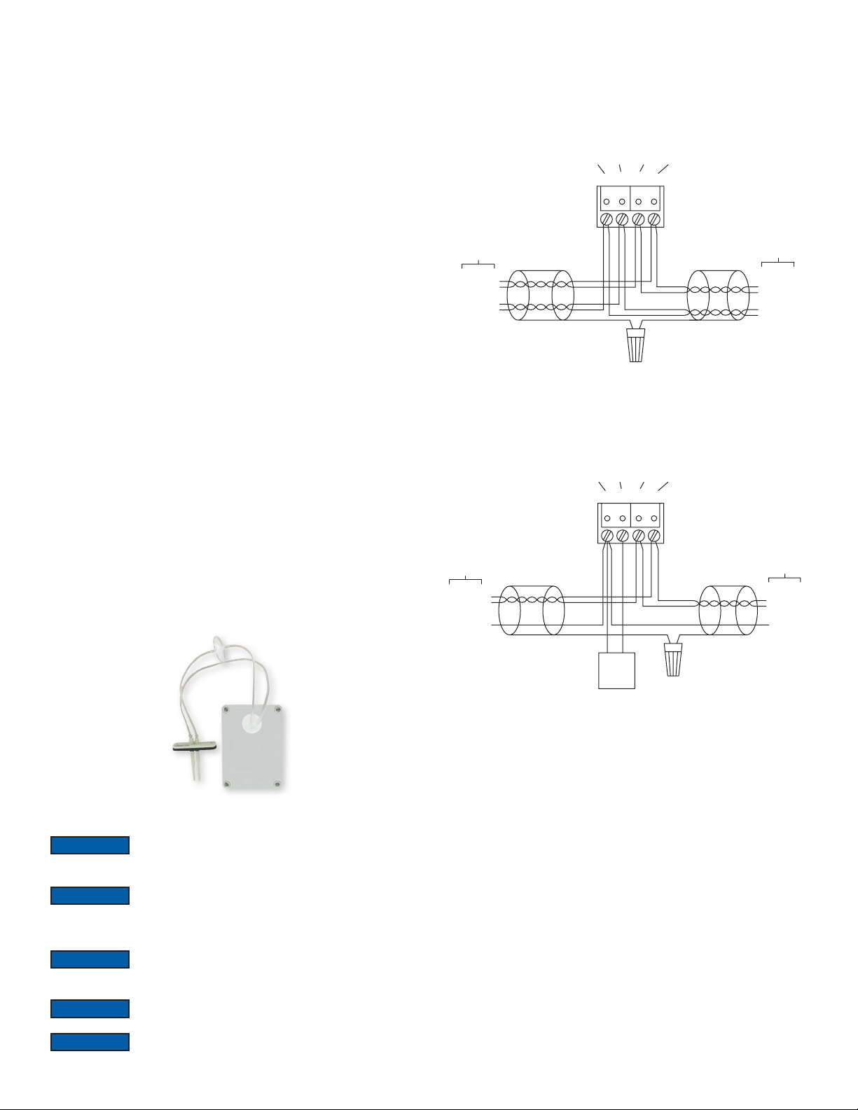
Duct Mounting
Duct mounting kit includes an air ow pitot tube, air lter with barbed connections, two
short pieces of tubing, and one long piece of tubing.
1. Mount the pitot tube into the duct observing the ow direction marked on the pitot
tube.
2. Attach the two short pieces of tubing to the barbed connections on each side of the
air lter. See Figure 2.
3. Attach the remaining side of one of the short pieces of tubing to the barbed
connection on the transmitter.
4. Attach the remaining side of the other short piece of tubing to the high port on the
pitot tube.
5. Attach the long piece of tubing to the open barbed connection on the transmitter.
6. Attach the other end of the long tubing to the low port on the pitot tube.
Figure 3 shows how to connect the GSTC in a network containing a common power
supply. Use a cable containing two twisted pairs. One pair is to be used for the power
and common. The other pair is to be used for A(-) and B(+). Attach the shields together
with a wire nut. This conguration is not suitable for AC supplies. Use a DC supply
only. Care should be taken that there are not too many devices powered from the
same supply as voltage drops will occur in the wiring. If you have many devices, or
have long cable runs, the local supply conguration, shown in Figure 4, may be a
better choice.
1234
PREVIOUS
DEVICE
B(+)
A(-)
PWR
COM
ATTA CH SHIELDS
TOGETHER W/WIRE NUT
TO NEXT
DEVICE
B(+)
A(-)
PWR
COM
Figure 3 - Common Power Supply
Figure 4 shows how to connect the GSTC in a network containing individual local
supplies. Use a cable containing a single conductor and a twisted pair. The single
conductor is to be used for common, and the pair is to be used for A(-) and B(+).
Attach the shields together with a wire nut. Both AC and DC supplies are suitable for
this conguration.
1234
PREVIOUS
DEVICE
B(+)
A(-)
COM
TO
DEVICE
B(+)
A(-)
COM
-+
ATTA CH SHIELDS
TOGETHER W/WIRE NUT
Figure 4 - Local Power Supply
All devices in the network should be daisy-chained. Star connections and T connections
are not permitted.
The A(-) and B(+) lines must be terminated at both ends with a 120 ohm resistor. If
the GSTC is an end device it has an on-board resistor that may be used. See Table
1 to enable it.
The network must be biased properly. If needed, there are bias resistors on-board the
GSTC. No more than two sets of bias resistors should be enabled in the network. See
Table 1 to enable them.
WIRING
NOTICE
Figure 2
Wiring should comply with Electrical Characteristics of Generators
and Receivers for Use in Balanced Digital Multipoint Systems,
TIA-EIA-485-A-1998, Telecommunications Industry Association, 1998.
NOTICE
BACnet installations should comply with ANSI/ASHRAE Standard
135-2010 BACnet A Data Communication Protocol for Building
Automation and Control Networks, American Society of Heating, Refrigerating and
Air-Conditioning Engineers, Inc., 2010.
®
communication protocol installations should comply with
NOTICE
and Implementation Guide V1.02, Modbus
NOTICE
Modbus
®
communication protocol over Serial Line Specication
Modbus
®
Organization, Inc., 2006.
Communication wiring must be in a daisy-chain fashion. Star
connections are not permitted.
NOTICE
Cable shield must be connected to earth ground at one location
only.
Page 3
Dip Switch Congurations
NETWORK BIAS
PROTOCOL NETWORK TERMINATION
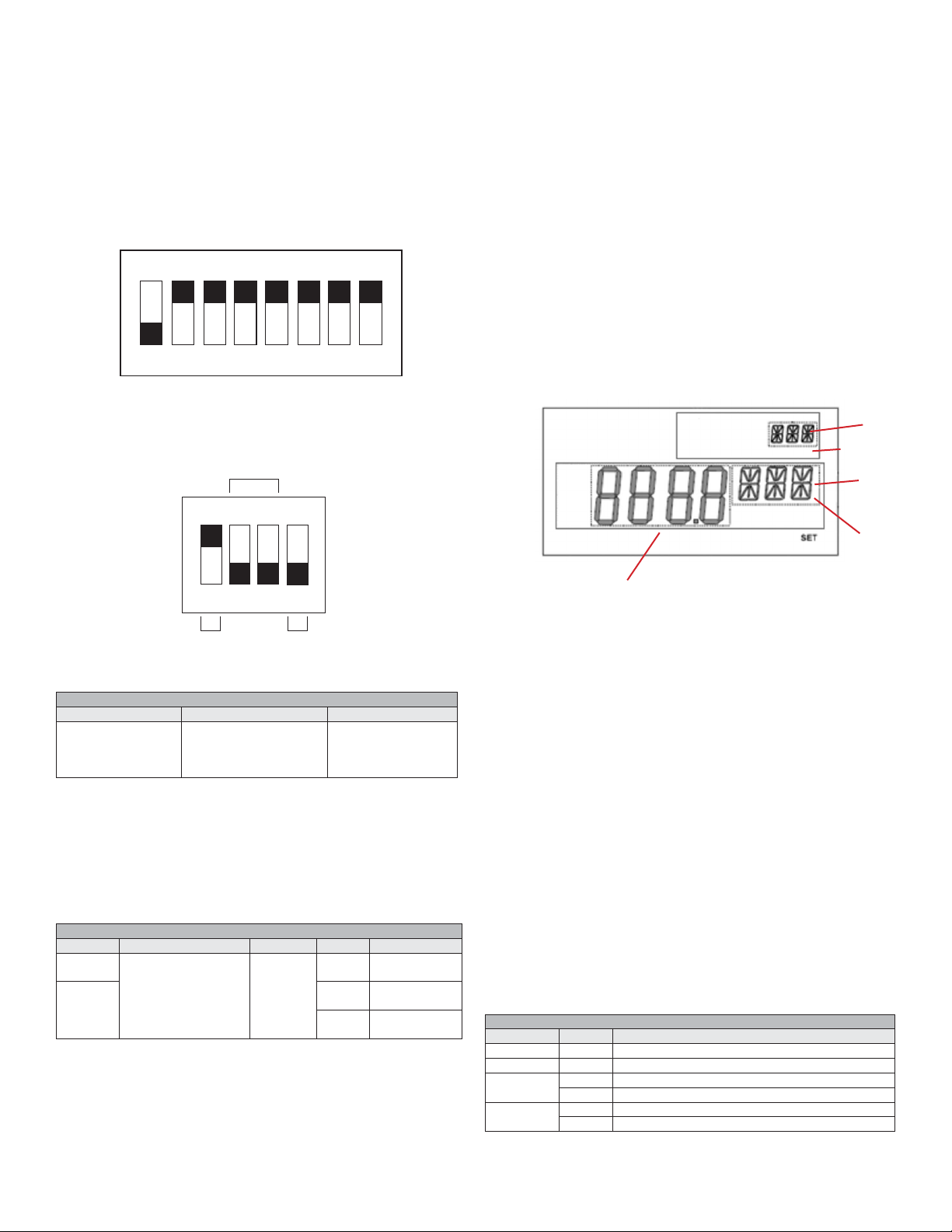
Use DIP Switch SW1 (see Figure 5) to congure the RS-485 address of the device. A
valid address depends on the protocol selected. Valid BACnet addresses range from
1 to 127. Valid Modbus
default, the device is shipped with Modbus
®
communication protocol addresses range from 1 to 247. By
®
communication protocol selected and the
address set to 127, as shown in Figure 5. A valid and unused address should be set
before connecting to an existing network. See Appendix I to congure the required
address using DIP Switch SW1. The device will not function properly if an invalid
address is set. During the power up sequence, the LCD (if present) will display the
RS-485 address as the primary value and either “BAC” to indicate BACnet or “MOD” to
indicate Modbus
®
communication protocol as the primary text. If the RS-485 address
is invalid, the invalid address is shown as the primary value with “ERR” as the primary
text, and the red LED will periodically blink once.
ON
1 2 3 4 5 6 7 8
Figure 5
To activate auto serial conguration, set a valid RS-485 address using DIP Switch
SW1, connect the serial bus, common and power wires, and apply power. The device
will power up and begin examining the serial bus for communication.
When the device is installed ofine or away from the main network, it is necessary to
generate the appropriate trafc in order to congure the serial communication whether
BACnet or Modbus
®
communication protocol is selected. While the serial conguration
is in progress, the device may not respond. The device may require multiple read
requests to complete the serial conguration process.
The auto serial conguration process is completed once a message addressed to the
device is received and processed successfully. If the serial conguration of the bus
changes, a power cycle of the device is required to restart the auto serial conguration
process.
More detailed information for BACnet protocol can be found in Appendix II, and
information for Modbus
®
communication protocol can be found in Appendix III.
MENU
The menu is only shown if a display is present. Figure 7 below outlines the display
components. To enter the menu, press and hold both the SPAN and ZERO pushbuttons
for at least 3 seconds. The menu descriptions and list of the available values for each
standard menu item is shown on in Table 3. Table 4 lists the available values for each
manual menu item.
Use DIP Switch SW2 (see Figure 6) to congure other hardware and software options.
Table 1 shows available options. Table 2 shows supported congurations for either
BACnet or Modbus
®
communication protocol.
ON
1 2 3 4
Figure 6
DIP SWITCH SW2 FUNCTIONS
Switch On Off
1 - Protocol
2 - B(+) Bias Resister
3 - A(-) Bias Resister
4 - Terminating Resister
®
Modbus
511Ω Pull-up to 5V
511Ω Pull-down to GND
120Ω between A(-) and B(+)
BACnet
Pull-up not connected
Pull-down not connected
Open
Table 1
Auto Serial Conguration
Use the auto serial conguration to enable the device to determine the baud rate,
parity, and stop bits directly from the serial trafc. After a valid RS-485 address is
chosen, the GSTC can be quickly and easily deployed. The auto serial conguration
procedure assumes a serial conguration appropriate to the chosen protocol, shown
in Table 2. Otherwise, the serial communication must be congured manually in the
setup menu.
SUPPORTED CONFIGURATIONS
Protocol Supported Baud Rates Data Size Parity Stop Bits
BACnet 9600
19200
®
Modbus
38400
57600
76800
8
None 1
Even
Odd
None 2
1
115200
Table 2
Text
Secondary
Display
Text
Primary
Display
Numeric
Figure 7
Standard Menu Descriptions
BAC or MOD: Displays the RS-485 address
CAL: Start user CO or NO2 calibration process
AUT: Auto serial conguration enabled
RST: Reset settings to factory default
Manual Menu Descriptions
BAU: Baud rate selection (only available if AUT = OFF)
PAR: Parity selection (only available if AUT = OFF)
STP: Stop bits selection (only available if AUT = OFF)
Menu Navigation
A menu owchart, located in Appendix IV, illustrates the navigation process.
1. Press and hold the SPAN pushbutton while in the menu to move to the previous
menu item.
2. Press and hold the ZERO pushbutton while in the menu to move to the next menu
item.
3. Press and hold both the SPAN and ZERO pushbuttons for 5 seconds to activate
the current menu item. In the lower left corner of the display “SET” is shown to
indicate a setting change.
4. Press and hold either the SPAN or ZERO pushbutton to change the setting.
5. Press and hold both the SPAN and ZERO pushbuttons for 5 seconds to accept the
setting.
6. After 30 seconds of inactivity, the display will return to normal operation.
STANDARD MENU OPTIONS
Menu Name Value Description
BAC or MOD xxx ADR RS-485 address (view only)
CAL xxx PPM Current CO or NO2 concentration
AUT ON Auto-baud will start and return to the main menu
OFF Starts the manual serial conguration menu sequence
RST NO
YES Will reset settings to factory default
Table 3
Page 4

MANUAL MENU OPTIONS
Menu Name Value Description
9600
19200
BAU
38400
57600
Only available if AUT = OFF
76800
115200
EVE
PAR
ODD
Only available if AUT = OFF
NON
STP
1
2
Only available if AUT = OFF
Table 4
SENSOR REPLACEMENT
A replacement sensor is available from Dwyer Instruments, Inc.
For CO, order part number: A-505.
2, order part number: A-506.
For NO
The address of the transmitter in Figure 9 is 127. This nal value is determined by
adding the individual values of the DIP switches together. The values for each DIP
switch are shown below in Table 5. When adding the individual values for Figure 9,
0+64+32+16+8+4+2+1=127, which is the correct factory setting.
DIP SWITCH VALUES
Switch Positions
Address Value112826433241658647281
Table 5
Another example would be if the desired address was 53. The only DIP switches in the
“ON” position would be switches 3, 4, 6, and 8 as shown in Figure 10 below. By adding
the individual values of each switch in the “ON” position, 0+0+32+16+0+4+0+1=53,
the desired address is obtained.
ON
WARNING
Sensors contain acid and are harmful if handled improperly. Do
not attempt to open sensors. Sensors should be disposed of
according to local laws.
Replacing The Sensor
1. Remove the cover plugs from the face of the unit and top cover. Locate the sensor,
see Figure 1. The sensor is mounted on three pin sockets. The circuit board is
either labeled “CO SENSOR” or “NO
2 SENSOR” underneath the sensor.
2. Remove and discard the used sensor.
3. Remove the shorting wire spring located at the bottom of the new sensor.
4. Install the new sensor into the three pin sockets.
5. The unit must be re-calibrated whenever a new sensor is installed.
6. Allow 30 minutes for the unit to come to temperature equilibrium prior to calibration.
The unit has internal temperature compensation, and the sensor must be at the
same temperature as the unit to calibrate properly.
CALIBRATION
Figure 8, located after Appendix III, shows how to set up a GSTC for calibration with an
auxiliary display. An auxiliary display is required for calibration unless an LCD model of
the GSTC was purchased. The procedure in Appendix IV shows how to set the range,
and calibrate the span and zero adjustments.
MAINTENANCE/REPAIR
Upon nal installation of the Series GSTC, no routine maintenance is required with
the exception of sensor replacement and calibration. As with all electrochemical
type gas sensors, routine calibration is required. It is recommended that units be recalibrated at 6 month intervals, to maintain the published accuracy, or as required by
local ordinances or other requirements. The units will maintain 5% accuracy if they are
re-calibrated at 12 month intervals.
Except for the sensor replacement and calibration, the Series GSTC is not eld
serviceable and should be returned if repair is needed. Field repair should not be
attempted and may void warranty.
This symbol indicates waste electrical products should not be disposed
of with household waste. Please recycle where facilities exist. Check with
your Local Authority or retailer for recycling advice.
1 2 3 4 5 6 7 8
Figure 10
NOTICE
The minimum possible address would be 0 when all DIP switches
are in the “OFF” position, and the maximum possible address
would be 255 when all DIP switches are in the “ON” position. When BACnet protocol
is selected the transmitter only has valid address from 1 to 127. When Modbus
communication protocol is selected the transmitter only has valid address from 1 to
247. Any address outside the selected protocol’s range will give an error.
Appendix II: BACnet Protocol
The GSTC supports objects that are listed below. Table 6 and Table 7 outlines each
item.
SUPPORTED BACNET OBJECTS
Object Type
Device
Analog Input
Dynamically
Creatable
No
No
Dynamically
Deletable
No
No
Object
Identier Object Name
607xxx
AI1
GSTC
CO Concentration
NO2 Concentration
Binary Value
Date Value
No
No
No
No
BV1
DV1
DV2
Zero Sensor
Calibration Date
Replace Sensor Date
Table 6
®
WARRANTY/RETURN
Refer to “Terms and Conditions of Sales” in our catalog and on our website. Contact
customer service to receive a Return Goods Authorization number before shipping the
product back for repair. Be sure to include a brief description of the problem plus any
additional application notes.
Appendix I: Setting the RS-485 Address
The address assignment is determined by adding the values for each of the switches
that are in the “ON” position. The transmitter comes from the factory with all of the DIP
switches in the “ON” position, except position 1 as shown in Figure 9 below.
ON
1 2 3 4 5 6 7 8
Figure 9
Page 5

OBJECT PROPERTIES
Property Default Value Property Data Type Access
Object Identier
Object Name
Object Type
System Status
Vendor Name
607xxx
“GSTC 607xxx”
DEVICE (8)
Operational (0)
“Dwyer
BACnetObjectIdentier
CharacterString (32)
BACnetObjectType
BACnetDeviceStatus
CharacterString
Read/Write
Read/Write
Read
Read
Read
Instruments, Inc”
Vendor Identier
Model Name
607
“GSTC-C” or
Unsigned
CharacterString
Read
Read
“GSTC-N”
Firmware Revision
Application Software
“?.?”
“?.?”
CharacterString
CharacterString
Read
Read
Version
Location
Description
Protocol Version
Protocol Revision
Protocol Services
“”
“CO Detector” or
2 Detector”
“NO
1
12
See pics
CharacterString (32)
CharacterString (32)
Unsigned
Unsigned
BACnetServicesSupported
Read/Write
Read/Write
Read
Read
Read
Supported
Protocol Object Types
Supported
Object List
Maximum APDU
See Table 2
See Table 2
128
BACnetObjectTypesSupported
BACnetArray
Unsigned
Read
Read
Read
Length Accepted
Segmentation
Supported
APDU Timeout
Number of APDU
NO_SEGMENTATION (3)
0
0
BACnetSegmentation
Unsigned
Unsigned
Read
Read
Read
Retries
Max Master
Max Info Frames
Devices Address
127
1
Empty
Unsigned
Unsigned
BACnetAddressBinding
Read/Write
Read
Read
Binding
Database Revision
Serial Number (1000)
1
“xxxxxx”
Unsigned
CharacterString
Read
Read
Table 7
The default object identier is 607xxx, where xxx is replaced by the address set by
the DIP Switch SW1. The object identier value will change as the address changes.
When a specic object identier is written via BACnet, that value is stored and changes
to the address will no longer affect the object identier. The object name reects the
current object identier. When a specic object name is written via BACnet, that value
is stored and changes to the object identier will no longer affect the object name.
Table 9 outlines the Binary Value (BV1) object which allows the sensor to be remotely
zeroed. When set to “ACTIVE”, the zero function will attempt to recalibrate the zero
point of the sensor.
BINARY VALUE
Property Default Value Property Data Type Access
Object Identier
Object Name
Object Type
Present Value
Status Flags
Event State
Reliability
Out of Service
BV1
“Zero Sensor”
BINARY VALUE (5)
0
0
NORMAL (0)
NO FAULT DETECTED (0)
FALSE (0)
BACnetObjectIdentier
CharacterString
BACnetObjectType
Real
BACnetStatusFlags
BACnetEventState
BACnetReliability
Boolean
Read
Read
Read
Read
Read
Read
Read
Read/Write
Read
Table 9
Table 10 outlines the Date Value (DV1) object which stores the date when the sensor
was last calibrated. Since the GSTC does not track time this value must be updated
manually after calibration is performed in the eld.
DATE VALUE
Property Default Value Property Data Type Access
Object Identier
Object Name
Object Type
Present Value
Status Flags
Event State
Reliability
Out of Service
DV1
“Calibration Date”
DATE VALUE (42)
????
{F,F,F,F}
NORMAL (0)
NO FAULT DETECTED (0)
FALSE (0)
BACnetObjectIdentier
CharacterString
BACnetObjectType
BACnetBinaryPV
BACnetStatusFlags
BACnetEventState
BACnetReliability
Boolean
Read
Read
Read
Read/Write
Read
Read
Read
Read/Write
Table 10
Table 11 outlines the Replace Sensor Date (DV2) object which stores the suggested
sensor replacement date. It is recommended to replace the sensor at specic intervals
because the sensor degrades over time. The GSTC does not track time so this value
must be updated manually after the sensor is replaced in the eld.
REPLACE SENSOR DATE
Property Default Value Property Data Type Access
Object Identier
Object Name
Object Type
Present Value
Status Flags
Event State
Reliability
Out of Service
DV2
“Replace Sensor Date”
DATE VALUE (42)
????
{F,F,F,F}
NORMAL (0)
NO FAULT DETECTED (0)
FALSE (0)
BACnetObjectIdentier
CharacterString
BACnetObjectType
BACnetBinaryPV
BACnetStatusFlags
BACnetEventState
BACnetReliability
Boolean
Read
Read
Read
Read/Write
Read
Read
Read
Read/Write
Table 11
Table 8 outlines the Analog Input (AI1) object which represents the current CO or NO
concentration reading in parts per million.
ANALOG INPUT
Property Default Value Property Data Type Access
Object Identier
Object Name
AI1
“CO Concentration” or
BACnetObjectIdentier
CharacterString
Read
Read
“NO2 Concentration”
Object Type
Present Value
Status Flags
Event State
Reliability
Out of Service
Units
ANALOG_INPUT (0)
Current reading
0
NORMAL (0)
NO_FAULT_DETECED(0)
FALSE (0)
Parts-per-million (96)
BACnetObjectType
Real
BACnetStatusFlags
BACnetEventState
BACnetReliability
Boolean
BACnetEngineeringUnits
Read
Read
Read
Read
Read
Read/Write
Read
Table 8
2
Page 6

BACnet Services
The GSTC supports the Device Communication Control Service BIBB. The option time
duration in minutes is also supported. This device is congured with a password that
must be provided to successfully execute the command. The password is “Dwyer”.
The GSTC also supports the Reinitialize Device Service BIBB. The supported device
states are “COLDSTART” and “WARMSTART”. All other states return an error. This
device is congured with a password that must be provided to successfully execute
the command. The password is “Dwyer”.
®
Appendix III: Modbus
Communication Protocol
The GSTC supports functions and input registers that are listed below. Table 12, Table
13, and Table 14 outline each item.
SUPPORTED MODBUS® FUNCTIONS
Function Name Function Code
Read Holding Registers
Read Input Registers
Write Single Register
Write Multiple Registers
03
04
06
16
Table 12
The string data type is read as a stream of ASCII characters with the rst character
sent in the MSB of the rst register and the second character sent in the LSB of the
rst register and so on. If the string is shorter than the allotted size, the remaining bytes
will be zero padded.
INPUT REGISTERS
Register Description Data Type Range
0001
CO or NO2 Concentration
in PPM
Unsigned 16 bit
integer
0 – 500 PPM CO,
0 – 100 (0 – 10.0) PPM
NO2
1000-1009
Model Number String
String
“GSTC-C” or
“GSTC-N”
1010-1013
1014-1017
Serial Number String
Firmware Version String
String
String
“xxxxxx”
“?.?”
Table 13
Figure 8
HOLDING REGISTERS
Register Description Data Type Value Range
0001
0500
Zero Sensor
Reboot device
Unsigned 16bit integer
Unsigned 16bit integer
0-1
0-1
0 or 1
0 - Do Nothing
1 - Warm Reset
Table 14
Writing 1 to the Zero Sensor register will re-zero the sensor just as if the user has
pressed the zero pushbutton.
®
The Reboot Device register allows a Modbus
communication protocol master to
remotely request this device to perform a warm reset. When a value of 1 is written to
this register the device will respond with success. The reset will take approximately 5
seconds after the command was received. Writing a value of 0 to this register has no
effect.
Page 7
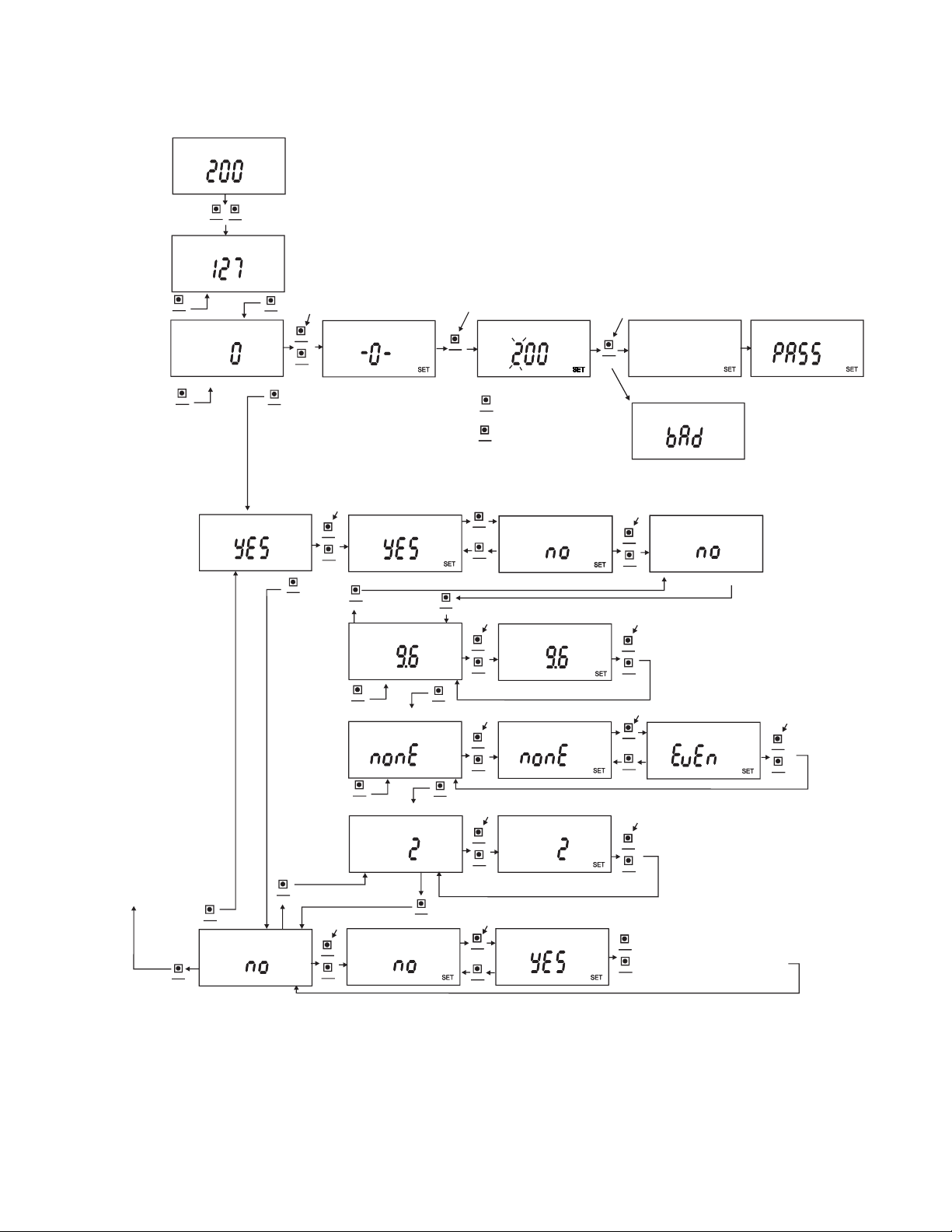
Appendix IV: Menu Flowchart and Calibration
NOTE - WHEN IN THE MENU, THE
MODBUS/BACNET
VIEW
DISPLAY WILL RETURN TO THE
HOME POSITION IF NO KEY IS
PRESSED WITHIN 30 SECONDS.
HOME POSITION, UNIT READS GAS
CONCENTRATION PPM
CO
PPM
SPAN
ZERO
DIGIT
VALUE
PRESS AND HOLD ZERO AND SPAN
KEYS FOR 5 SECODNS TO ENTER
THE MAIN MENU.
ADDRESS.
ABLE ONLY.
SPAN
DIGIT
CALIBRATION
MODE
COMMUNICATION
SETTINGS
FACTORY SETTING IS
AUTO BAUD ON.
SCROLL TO TOP
MENU, MODBUS/BACNET
ADDRESS
RESET UNIT
TO FACTORY
DEFAULTS
ZERO
VALUE
SPAN
DIGIT
SCROLL
SCROLL
SPAN
DIGIT
SCROLL
ADR
SCROLL
PPM
SCROLL
MOD
ZERO
PRESS ZERO AND SPAN TO ENTER CALIBRATION MODE
VALUE
CO
ZERO
VALUE
SPAN
DIGIT
PLACE THE UNIT IN AN AREA THAT CONTAINS FRESH
AIR (NO CO OR NO2 GAS). ALLOW 3 MINUTES TO
STABILIZE.
ZERO
VALUE
PRESS AND HOLD ZERO AND SPAN UNTIL
“SET” TURNS ON
AUT
ZERO
VALUE
SPAN
DIGIT
SCROLL
ZERO
SPAN
DIGIT
VALUE
SET BAUDRAT E
RST
SPAN
DIGIT
SPAN
DIGIT
SETPARITY
SETSTOPBITS
SCROLL
PRESS AND HOLD ZERO AND
SPAN UNTIL “SET” TURNS ON
ZERO
VALUE
SPAN
DIGIT
SPAN
DIGIT
SCROLL
SCROLL
SCROLL
PRESS THE ZERO KEY FOR 5 SECONDS. THE
ZERO VALUE IS STORED AND THE DISPLAY
SEQUENCES TO THE SPAN GAS CALIBRATION VALUE
CAL
ZERO
VALUE
TO ADJUST THE DISPLAY TO SET
THE DESIRED SPAN CALIBRATION VALUE,
PRESS THE DIGIT KEY TO SCROLL
SPAN
THROUGH THE DIGITS. THE DIGITS WILL
DIGIT
BLINK AS THEY ARE SELECTED.
ADJUST THE VALUE OF THE DIGIT
ZERO
USING THE VALUE KEY
VALUE
HOOK UP THE UNIT TO THE SPAN CALIBRATION GAS
USING THE CALIBRATION ADAPTER A-507AS SHOW IN FIG. 8
SPAN GAS FLOW IS TO BE BETWEEN 0.5 TO 10. SLPM.
ALLOW GAS TO FLOW FOR AT LEAST 3 MINUTES.
PRESS ZERO OR SPAN TO SWITCH
BETWEEN AUTO BAUD ON OR OFF
ZERO
AUT
VALUE
SPAN
DIGIT
AUTOBAUD MUST BE SET TO “NO” TO SET
BAUDRATE, PARITY AND STOP BIT SETTINGS
SCROLL
ZERO
VALUE
BAU
K
SCROLL
ZERO
VALUE
PAR
SCROLL
ZERO
VALUE
STPSTP
ZERO
VALUE
RST
PRESS AND HOLD ZERO AND SPAN UNTIL
“SET” TURNS OFF
ZERO
VALUE
SPAN
DIGIT
USING ZERO AND SPAN KEYS, SET BAUDRATE
TO DESIRED VALUE
PRESS AND HOLD ZERO AND SPAN UNTIL
“SET” TURNS ON
ZERO
VALUE
SPAN
DIGIT
PRESS AND HOLD ZERO AND SPAN UNTIL
“SET” TURNS ON PRESS AND HOLD ZERO AND SPAN UNTIL
ZERO
VALUE
SPAN
DIGIT
USING ZERO AND SPAN KEYS, SET STOP BIT
TO 1 OR 2
PRESS ZERO OR SPAN TO SWITCH
BETWEEN YES OR NO
ZERO
VALUE
SPAN
DIGIT
CAL
PPM
PRESS AND HOLD THE SPAN KEY FOR 5 SECONDS
CAL
SPAN
DIGIT
DISPLAY READS “CAL” THEN “PASS” AND RETURNS TO HOME POSITION
PRESS AND HOLD ZERO AND SPAN UNTIL
“SET” TURNS OFF
AUT
AUT
ZERO
VALUE
SPAN
DIGIT
SCROLL
PRESS AND HOLD ZERO AND SPAN UNTIL
BAU
K
PAR
RST
“SET” TURNS OFF
ZERO
VALUE
SPAN
DIGIT
PRESS ZERO OR SPAN TO SWITCH
BETWEEN NO PARITY OR EVEN OR
ODD PARITY
ZERO
VALUE
SPAN
DIGIT
“SET” TURNS OFF
ZERO
VALUE
SPAN
DIGIT
IF RESET IS SET TO YES, PRESSING ZERO AND SPAN
WILL CAUSE A FACTORY RESET, AND DISPLAY WILL
ZERO
RETURN TO THE HOME POSITION
VALUE
IF RESET IS SET TO NO, PRESSING ZERO AND SPAN
SPAN
DIGIT
OK
IF THE SENSOR OUTPUT IS NO LONGER
SUFFICIENT FOR CALIBRATION, THEN
THE DISPLAY READS “BAD SEN”. THE
SENSOR MUST BE REPLACED
SEN
AUT
AUT
PAR
PRESS AND HOLD ZERO
AND SPAN UNTIL
“SET” TURNS OFF
ZERO
VALUE
SPAN
DIGIT
CAL
Page 8

NOTES
__________________________________________________________________________________________________________________________________________
__________________________________________________________________________________________________________________________________________
__________________________________________________________________________________________________________________________________________
__________________________________________________________________________________________________________________________________________
__________________________________________________________________________________________________________________________________________
__________________________________________________________________________________________________________________________________________
__________________________________________________________________________________________________________________________________________
__________________________________________________________________________________________________________________________________________
__________________________________________________________________________________________________________________________________________
__________________________________________________________________________________________________________________________________________
__________________________________________________________________________________________________________________________________________
__________________________________________________________________________________________________________________________________________
__________________________________________________________________________________________________________________________________________
__________________________________________________________________________________________________________________________________________
__________________________________________________________________________________________________________________________________________
__________________________________________________________________________________________________________________________________________
__________________________________________________________________________________________________________________________________________
__________________________________________________________________________________________________________________________________________
__________________________________________________________________________________________________________________________________________
__________________________________________________________________________________________________________________________________________
__________________________________________________________________________________________________________________________________________
__________________________________________________________________________________________________________________________________________
__________________________________________________________________________________________________________________________________________
__________________________________________________________________________________________________________________________________________
__________________________________________________________________________________________________________________________________________
__________________________________________________________________________________________________________________________________________
Printed in U.S.A. 2/19 FR# 443872-00 Rev. 6©Copyright 2019 Dwyer Instruments, Inc.
DWYER INSTRUMENTS, INC.
P.O. BOX 373 • MICHIGAN CITY, INDIANA 46360, U.S.A.
Phone: 219/879-8000
Fax: 219/872-9057
www.dwyer-inst.com
e-mail: info@dwyermail.com
 Loading...