

Page 1
Bulletin P-DPT
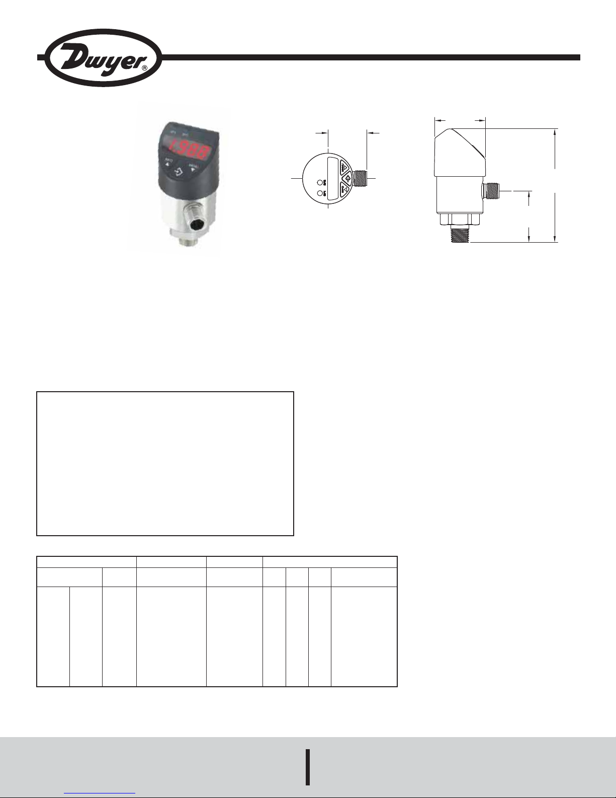
1-5/32
[29.50]
1-1/2
[38.00]
1-33/64
[38.60]
3-23/64
[85.40]
Operating Modes
System start
- Display is fully activated for 2s
Display Mode
- Normal operation, displays system pressure
Programming Mode
- Setting Parameters
4-digit LED display - Display system pressure
- Display Menu Item
- Display Parameter
1. LED (red)
- Status Switch Output 1
2. LED (red)
- Status Switch Output 2 (Optional)
-When the pressure switch is powered up within
the range of the hysteresis, the output switch is
set to “not active” by default
Series DPT Digital Pressure Transmitter with Switches
Specifications - Installation and Operating Instructions
The Series DPT Digital Pressure Transmitter with Switches combines a large,
14-segment LED display with two programmable solid state switches into one
compact unit. A unique, 3-way rotating design allows the DPT to meet specific
installation requirements without any retrofitting. The display and electrical
connection can be rotated independently to maximize visibility while still orienting
the electrical connection in the best position for the cable connector. Large,
ergonomically designed push buttons allow for quick/easy programming and thinfilm piezoresitive sensor technology guarantees long-term reliability and stability.
INSTALLATION
When installing gage always use a hex at the base of the housing to tighten the
gage to a mating fitting. Do not apply wrench to housing.
POWER UP
UNITS CHART
Model
DPT-V00
DPT-V01
DPT-V02
DPT-V03
DPT-V04
DPT-V05
DPT-V06
DPT-V07
DPT-V08
DPT-V09
DPT-V10
*feet of seawater @ 4°C
DPT-A00
DPT-A01
DPT-A02
DPT-A03
DPT-A04
DPT-A05
DPT-A06
DPT-A07
DPT-A08
DPT-A09
DPT-A10
Range
(psig)
-14.5 to 0
0 to 15
0 to 25
0 to 30
0 to 50
0 to 100
0 to 160
0 to 200
0 to 300
0 to 500
0 to 1000
DWYER INSTRUMENTS, INC.
P.O. BOX 373 • MICHIGAN CITY, INDIANA 46361, U.S.A. Fax: 219/872-9057 e-mail: info@dwyer-inst.com
Maximum Pressure
(psig)
30
30
60
60
100
200
290
400
600
1000
1740
Burst Pressure
(psig)
75
75
150
150
250
500
500
1500
1500
2500
7975
bar
1.034
1.034
1.724
2.068
3.447
6.895
11.03
13.79
20.68
34.47
68.95
MPa
.1034
.1034
.1724
.2068
.3447
.6895
1.103
1.378
2.068
3.447
6.895
SPECIFICATIONS
Service: Compatible gases, liquids or vapors.
Wetted Materials:
Pressure connection: 316 L SS;
Pressure sensor: 316 L SS (13-8 PH for ranges above 150 psi).
Housing: 316 L SS lower body, heat and chemical resistant fiberglass reinforced
plastic (PBT) plastic head, TPE-E keyboard, PC display window.
Accuracy: 1.0% F.S. (includes non-linearity, hysteresis, zero point).
Pressure Limit: See table.
Temperature Limits: 32 to 176°F (0 to 80°C).
Process Connections: 1/4˝ male NPT.
Display: Red LED 4-digit (0.35˝ H digits).
Weight: 7 oz (0.2 kg).
SWITCH SPECIFICATIONS
Switch Type: PNP.
Electrical Rating: 250 mA.
Electrical Connections: M 12x1, 5-pin.
Mounting Orientation: Mount in any position.
TRANSMITTER SPECIFICATIONS
Temperature Limits: 32 to 176°F (0 to 80°C).
Thermal Effect: 0.2% FS / 10k.
Power Requirements: 15 to 35 VDC.
Output Signal: DPT-A: 4 to 20 mA; DPT-V: 0 to 10 VDC.
Loop Resistance: DPT-A: ≤ 0.5k; DPT-V: > 10k.
Power Consumption: ≤ 100 mA.
Electrical Connections: M 12x1, 5-pin.
Enclosure Rating: IP65 and IP67.
Agency Approvals: CE.
Pressure Ranges
2
kPa
103.4
103.4
172.4
206.8
344.7
689.5
1103
1378
2068
3447
6895
kg/cm
1.055
1.055
1.758
2.109
3.515
7.031
11.25
14.06
21.09
35.15
70.31
Phone: 219/879-8000 www.dwyer-inst.com
Page 2
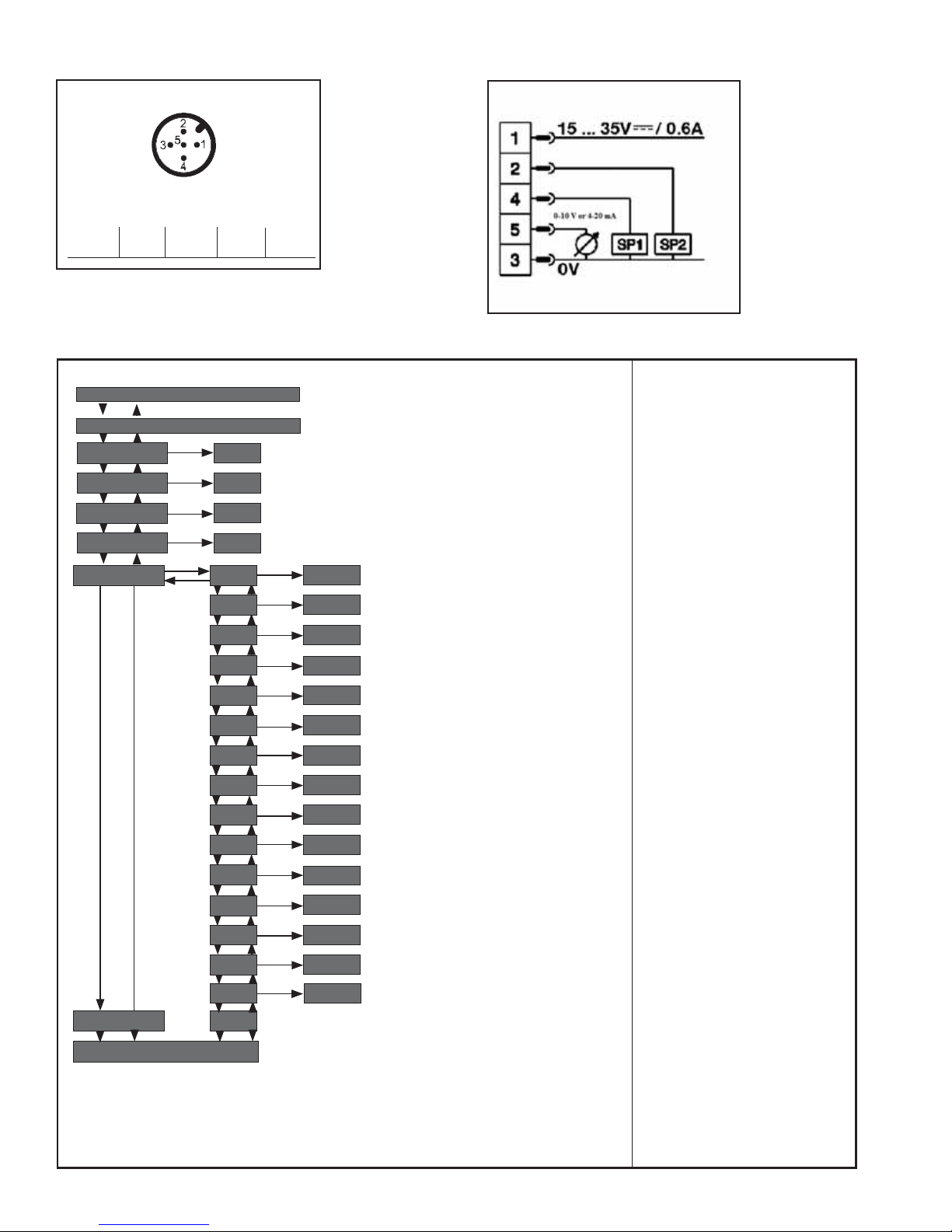
WIRING
Circular connector M12x1, 5-pin
2 switching outputs + 1 analogue output
+ = 1 - = 3
PROGRAMMING
SP1 = 4
0-10 V or 4-20 mA
SP2 = 2 = 5
Menu (Programming and Factory Setting)
Display-Mode
Long press on Menu Key
Programming-Mode
SP1 / FH1
RP1 / FL1
SP2 / FH2
RP2 / FL2
EF
value
value
value
value
RES
DS1
DR1
DS2
YES/NO
value
value
value
Factory Setting:
(Min: LLR + 0.5% Max: ULR) Instrument Nominal Pressure
(Min: LLR Max: SP1 - 0.5%) Instrument Nominal Pressure - 10%
(Min: LLR + 0.5% Max: ULR) Instrument Nominal Pressure
(Min: LLR Max: SP2 - 0.5%) Instrument Nominal Pressure-
(Return to Factory Settings)
(0 … 50 s) 0 s
(0 … 50 s) 0 s
(0 … 50 s) 0 s
10%
END
Display-Mode
Legend:
LLR = lower limit of range
ULR = upper limit of range
DR2
OU1
OU2
UNIT
0SET
DISM
DISU
DISR
RHL
PAS
TAG
END
value
PARA
PARA
unit
YES/NO
PARA
value
YES/NO
YES/NO
value
value
(0 … 50 s) 0 s
(HNO, HNC, FNO, FNC) HNO
(HNO, HNC, FNO, FNC) HNO
(BAR, MPA, KPA, PSI, KG/cm²) Order dependent
(Zero Point Offset adjustment max. 3 %)
(ACT, HIGH, LOW, OFF,
SP1/FH1, RP1/FL1, SP2/FH2, RP2/FL2) ACT
(1/2/5/10 Updates/Second)
5 / s
(Display rotate 180°)
(Reset HIGH, LOW)
(Password) without
(Measuring Point number) without
Page 3

BUTTON OPERATION
Hysteresis function
If the system pressure fluctuates around the nominal value,
the hysteresis keeps the switch status of the outputs stable.
When the system pressure is rising, the output switches when it
reaches the respective set point (SP); if the pressure falls again,
the output switches back only if the reset point (RP) is reached.
Application example: loading an accumulator.
The shut-off valve loads up to 8o bar and then shuts off. When
70 bar is reached again, it switches on once more.
Window function
The window function allows the monitoring of a defined range.
If the system pressure is between the window high (FH) and the
window low (FL), the output is activated (NO) respective
deactivated (NC).
Delay times (0.00 to 50 s):
By this means unwanted pressure peaks of short duration or high
frequency can be filtered out.
The pressure must remain for at least this time to enable the
switch to operate. The switching output does not immediately
change its status when it reaches the switching event, but only
after the delay time has elapsed. If the switching event no longer
pertains when the delay time has elapsed, the switching output
does not change.
Error Display Description
ATT1 On changing the Switch Point the system automatically reduces the Reset Point
ATT2 Zero Point adjustment error, current pressure is outside the limits
ATT3 Password entered for Menu access is incorrect
ERR Internal error
OL Overpressure, measuring range exceeded > approx. 5% (Display blinks)
UL Underpressure, under measuring range < approx. 5% (Display blinks)
Acknowledgement of an Error Display by pressing the ˝Enter˝ key.
Display-Mode Programming-Mode
short press:
INFO
Display units
long press:
Run-through Parameter Info
1. UNIT + unit
2. SP1 / FH1 + value
3. RP1 / FL1 + value
4. SP2 / FH2 + value (optional)
5. RP2 / FL2 + value (optional)
6. LOW + value
7. HIGH + value
8. TAG + value (Only display when value set)
short press:
Display units
MENU
long press:
Switch to Programming Mode
If the password is set to <> 0000, a pass
word will be requested. If authentication is
successful, then it enters the Program Mode,
otherwise it reverts to Display Mode.
short press:
Display units
INFO
short press:
- Menu up
- Increase parameter value
long press:
- Menu up
- Increase parameter value
short press:
- Menu down
- Decrease parameter value
long press:
- Menu down
- Decrease parameter value (Increment rate is time dependent)
long press (during Restart, keep pressed)
short press:
- Select Menu Item
- Confirmation of the entry (Parameter value)
+
MENU
short press (both keys at the same time):
Return to Display Mode
SWITCH FUNCTION
ERROR
Page 4

PARAMETERS
Parameter Description
SP1 / SP2 Hysteresis function: Switch point switch output (1 or 2)
FH1 / FH2 Window function: Window high switch output (1 or 2)
RP1 / RP2 Hysteresis function: Reset point switch output (1 or 2)
FL1 / FL2 Window function: Window low switch output (1 or 2)
EF Enhanced Programming Functions
RES Return the set parameter to the Factory Settings
DS1
DS2
DR1
DR2
OU1 Switching Function Switching Output (1 or 2)
OU2 HNO = Hysteresis Function, normally open
UNIT Changing Units
0SET Zero Point adjustment (+ 3% of Nominal Pressure)
DISM Display value in Display Mode
DISU Display-Update 1, 2, 5, 10 Updates/Second
DISR Display rotate 180°
RHL Clear the Min- and Max-value memory
PAS Password input, 0000 = no password
TAG Input of a 16-digit alphanumeric Measuring Point number
Switch Delay Time, which must occur without interruption before any electrical signal change occurs
(SP1 or SP2)
Switch Delay Time, which must occur without interruption before any electrical signal change occurs
(RP1 or RP2)
HNC = Hysteresis Function, normally closed
FNO = Window Function, normally open
FNC = Window Function, normally closed
(If the pressure range is higher than the display range, no change of the unit is posssible
and the parameter UNIT is not shown)
ACT = Current System Pressure, LOW, HIGH = Minimum, Maximum System Pressure, OFF = Display off;
SP1/FH1 = Function switch point 1, RP1/FL1 = Function reset point1,
SP2/FH2 = Function switch point 2, RP2/FL2 = Function reset point 2
Password input Digit by Digit
TROUBLESHOOTING
Failure Possible cause Procedure
No output signal Cable break Check connections and cable
No output signal No/incorrect voltage supply
No/False output signal Incorrectly wired
Output signal unchanged after change
Abnormal zero point signal Overload limits exceeded
Signal span too small
Signal span too small Power supply too high/too low
WARRANTY
Upon final installation, no routine maintenance is required. A periodic check of the
calibration is recommended. The series DPT is not field serviceable and should be
returned if repair is needed (field repair should not be attempted and may void
warranty). Be sure to include a brief description of the problem plus any relevant
application notes. Contact customer service to receive a returns goods authorization
number before shipping.
in pressure
Mechanical overload through over pressure
Mechanical overload through over pressure
Adjust the voltage supply to correspond
with the Operating Instructions
Follow pin assignment (see Instrument
Label / Operating Instructions)
Replace instrument; if failure reoccurs,
consult the manufacturer
Ensure permissible overload limits are
observed (see Operating Instructions)
Replace instrument; if failure reoccurs,
consult the manufacturer
Correct the power supply in line with
the Operating Instructions
11609185.01
10/2010
©Copyright 2010 Dwyer Instruments, Inc. Printed in U.S.A. 10/10 FR# RA-443873-00 Rev. 1
DWYER INSTRUMENTS, INC.
Phone: 219/879-8000 www.dwyer-inst.com
P.O. BOX 373 • MICHIGAN CITY, INDIANA 46361, U.S.A. Fax: 219/872-9057 e-mail: info@dwyer-inst.com
 Loading...