

Page 1
Series DPMX Extra Large Digital Panel Meter
Specifications - Installation and Operating Instructions
10-19/32
MINIMUM PANEL
CLAMP DIM.
(MAXIMUM PANEL
THICKNESS 1/2˝)
[12.70]
1-31/32
[50.04]
(2-43/64)
[67.87]
[261.11]
10-19/32
[269.24]
Bulletin G-62
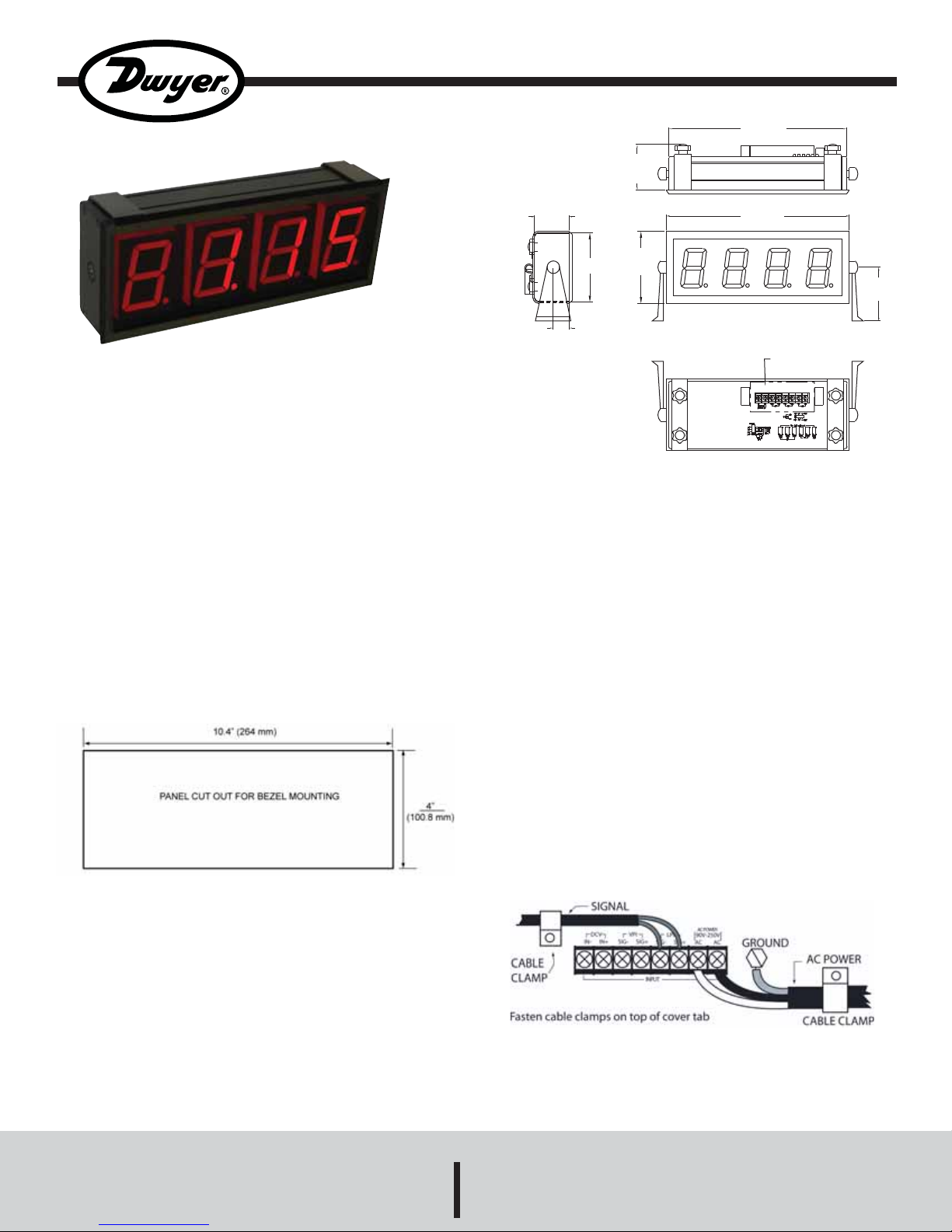
The Series DPMX Extra Large LED Digital Panel Meter can
easily be viewed from across a room or in dark areas. The 2.3”
LED segments are available in red, green, or blue. These panel
meters come equipped with a universal power supply and user
selectable process inputs to fit most applications. The Series
DPMX includes a mounting bracket that can be adjusted up to
180°.
INSTALLATION
The Series DPMX is designed to be bezel mounted or gimbal
mounted. Mounting brackets are included in the box.
BEZEL MOUNT
Remove the two U-brackets from the back of the panel meter.
Slide the unit through the panel from the front. Next, attach the Ubrackets to the rear and tighten the four retaining bolts.
See Figure 1 for dimensions of the cutout.
4-5/32
[105.66]
REMOVABLE
COVER
3-7/64
[78.99]
29/32
[22.86]
4[101.60]
SPECIFICA T IONS
Inputs Ranges: Set Voltage: ±200 mVDC, ±2 VDC, ±20 VDC.
Adjustable Voltage: 200 mVDC, 5 VDC, 10 VDC.
Adjustable Current: 0(4) to 20 mA DC.
Inputs Impedance: Set Voltage: >1 MΩ (>10 MΩ on 200 mV range).
Adjustable Voltage: 392 kΩ.
Adjustable Current: 300Ω nominal.
Accuracy: ±(1% F.S. + 1 count).
Power Supply: 90 to 250 VAC @12 VA or 10.5 to 30 VAC/DC @
6VA (depending on model).
Display: 3-1/2 digits, 2.3” height, 7 segment LED.
Sampling Rate: 3 readings per second.
Operating Temperature: -10 to 50ºC.
Storage Range: -40 to 75ºC.
Warm Up: 10 minutes.
Mounting: 180º gimbal mounting with 30º stops or bezel mount.
WIRING
The unit accepts signal inputs of 200 mVDC, 2 VDC, 5 VDC, 20
VDC, 10 VDC, and a 4 to 20 mA DC loop. The screw terminals for
wiring are located on the back of the adder board beneath the
cover. The cable clamps must be unfastened to access the screw
terminals. In order to reduce electrical noise, install the line voltage
and the process signal through separate cable clamps as shown
Figure 1
in Figure 2.
GIMBAL MOUNT
If the panel meter is to be gimbal mounted, remove and discard
the two U-brackets from the back of the panel meter. Fasten the
gimbal brackets to the mounting surface using appropriate
hardware. Lastly, fasten the panel meter loosely to the gimbals
using the thumbscrews. Note that detents are provided on both
sides of the case. Adjust the meter to the desired viewing angle
and securely tighten the thumb screws.
Figure 2
On the terminal cover, remove two thin break out sections that
best match the diameter of the wiring cables being used.
DWYER INSTRUMENTS, INC.
Phone: 219/879-8000 www.dwyer-inst.com
P.O. BOX 373 • MICHIGAN CITY, INDIANA 46361, U.S.A. Fax: 219/872-9057 e-mail: info@dwyer-inst.com
Page 2
OPERA TION
FUNCTION
The Series DPMX panel meter can be used with voltage or current
signal inputs. It is important that the signal wires be connected to
the proper terminals as labeled in Figure 2. Along with wiring to the
proper terminals, the proper input should be selected using the
function selection switch shown in Figure 3. For current inputs, the
function switch should be set to LPI. For adjustable voltage inputs,
the function switch should be set to VPI. For fixed voltage inputs,
the function switch should be set to DCV.
LPI
VPI
DCV
FUNCTION
Figure 3
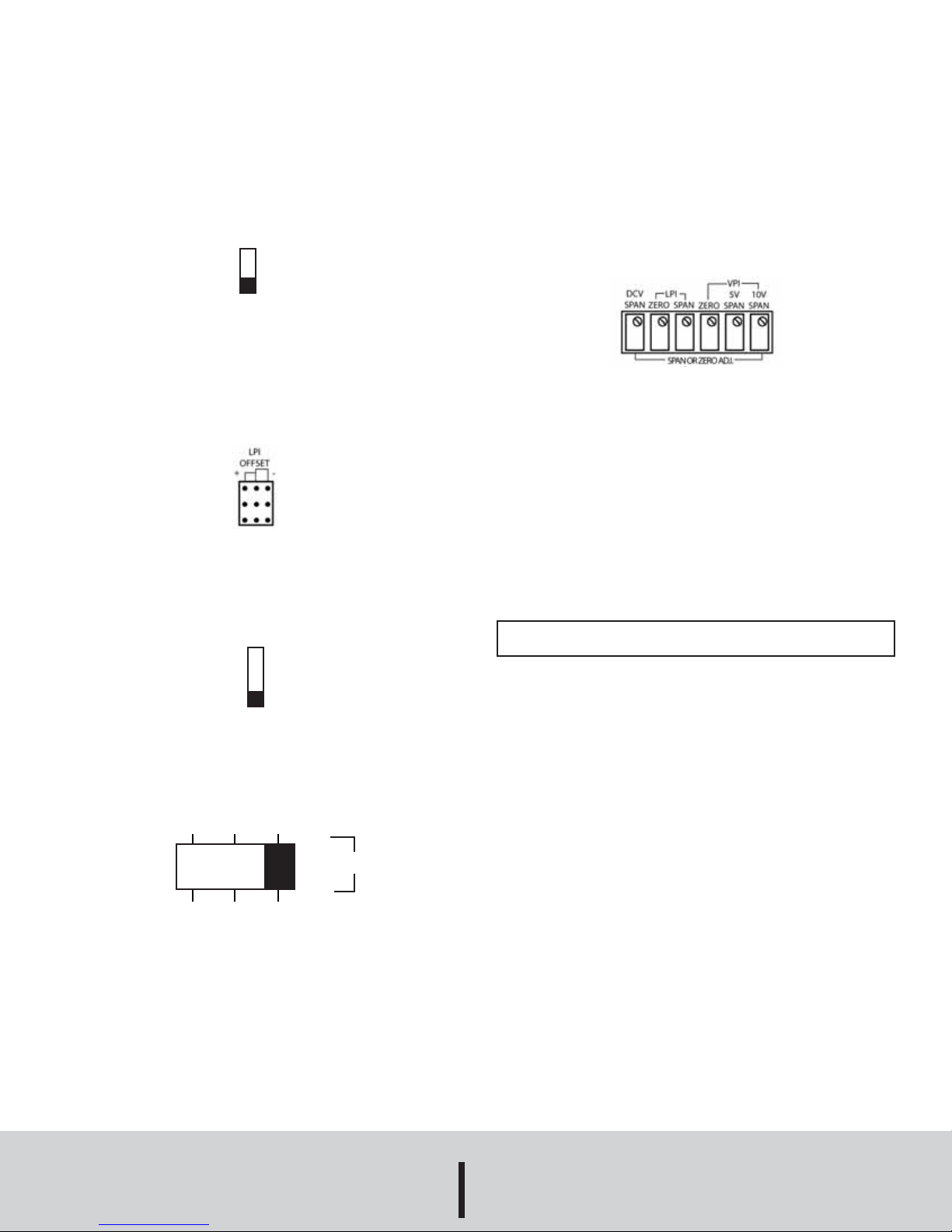
ZERO SUPPRESSION FOR CURRENT INPUT
The Series DPMX can be used with either 0 to 20 mA or 4 to 20
mA current inputs. In order to maximize the rangeability of the
meter, the LPI offset jumper should be set to “+” for 4 to 20 mA
signal inputs or to “-” for 0 to 20 mA inputs.
See Figure 4.
Figure 4
SELECTING DECIMAL POINT POSITION
Four decimal point positions are available on the digital panel
meter, DP1-OFF. Move the switch to the corresponding decimal
point location. See Figure 5.
DP1
DP2
DP3
OFF
DECIMAL
Figure 5
SPAN & ZERO ADJUSTMENT
The unit is equipped with a span adjustment for DCV inputs, and
both span and zero adjustments for LPI and VPI inputs. To use
either function, a flathead screwdriver is required to set the
appropriate values. First, choose the span and/or zero adjustment
that corresponds with the input that is being supplied. For
example, if a VPI inputs is being supplied to the meter, you will
need to adjust the VPI span. Next, apply the lowest input into the
meter and adjust the zero position for the required reading. After
adjusting the zero position, apply the highest input into the meter
and adjust the span position for the meter. Recheck the zero input
and readjust as needed. See Figure 6.
Figure 6
MAINTENANCE
Upon final installation of the Series DPMX LED Digital Panel Meter,
no routine maintenance is required. A periodic check of the system
calibration is recommended. The Series DPMX is not field
serviceable and should be returned if repair is needed (field repair
should not be attempted and may void warranty). Be sure to
include a brief description of the problem plus any relevant
application notes. Contact customer service to receive a return
goods authorization number before shipping.
CAUTION! Do not mount the panel meter outdoors or in damp
environments, or other extreme environments. It is not a sealed unit.
SELECTING VOLTAGE INPUT RANGE
Three input positions are available for either VPI or DCV (see Figure
3 above). Move the switch to desired input range (see Figure 7).
200 mV 5V 10V
200 mV 2V 20V
VPI
RANGES
DCV
Figure 7
©Copyright 2008 Dwyer Instruments, Inc. Printed in U.S.A. 11/08 FR# R5-443568-00 Rev. 2
DWYER INSTRUMENTS, INC.
Phone: 219/879-8000 www.dwyer-inst.com
P.O. BOX 373 • MICHIGAN CITY, INDIANA 46361, U.S.A. Fax: 219/872-9057 e-mail: info@dwyer-inst.com
 Loading...