

Page 1
Bulletin G-64
Series DPMA-5 Adjustable LCD Digital Panel Meters
Specifications - Installation and Operating Instructions
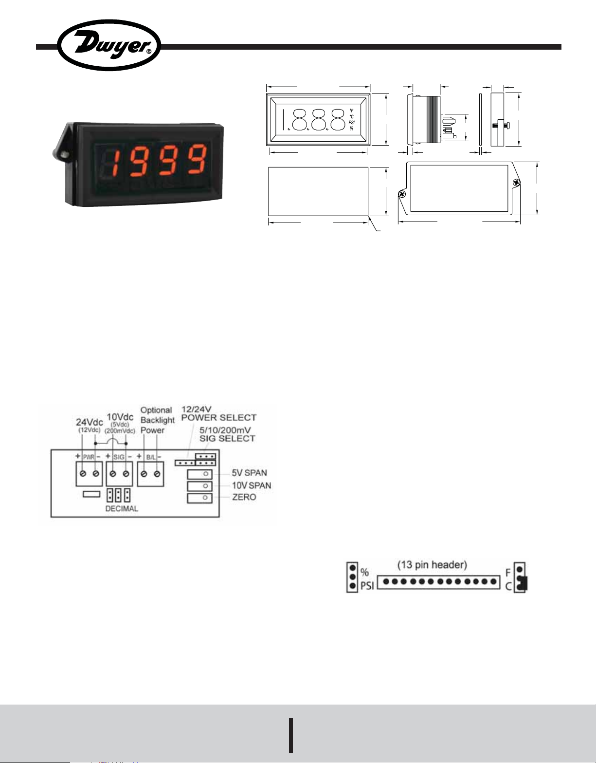
Series DPMA-5 Adjustable Panel Meter offers a large 1˝, 3-1/2
digit display for easy viewing in a standard 1/8 DIN package. Unit
accepts voltage inputs with a wide bipolar zero and span
adjustment. Standard features include field selectable engineering
units and decimal point positions. Choose from red, amber, or
green segments for easy viewing at a distance. A separate 24 VDC
power supply is required for the operation of the backlight.
INSTALLATION
The Series DPMA-5 is designed to snap into a 3.62˝ (92 mm) W x
1.77˝ (45 mm) H panel cutout. No additional hardware is required.
WIRING
3-25/32 [96.0]
3-35/64 {89.9]
PANEL CUTOUT
FOR SNAP IN MOUNTING
3-5/8 [92.1]
1-57/64 [48.0]
1-49/64 [45.0]
4X 1/64 [.25]
1 [25.4]
MOUNTING BRACKET OUTLINE
15/32 [11.9]
63/64 [24.9]
3/16 [4.76]
REAR VIEW
4-29/64 [113.0]
SPECIFICATIONS
Input: 0-5 VDC; 0-10 VDC.
Accuracy: ±(0.05% FS + 1 count).
Power Supply: 12 or 24 VDC (field selectable).
Current Consumption: 10 mA DC. Backlight: 35 mA.
Span and Zero: Adjustable. (±1999 counts).
Display: 3-1/2 digits, 7 segments, 1˝ (25.4 mm) H.
Decimal Points: 3-position, user selectable.
Annunciator: °F, °C, %, PSI.
Polarity: Automatic, “-” displayed.
Operating Temperature: 14 to 122°F (-10 to 50°C).
Storage Temperature: -40 to 167°F (-40 to 75°C).
Mounting: Snap-in panel mount or clamp (gasket included).
Connection: Screw terminals.
Weight: 4 oz (113.4 g).
Conversion Rating: 3 per second.
Warm-up: 10 minutes typical.
1-15/16 [49.2]
5/64 [1.9]
1-59/64 [48.8]
OPERATION
Selecting Engineering Units
Four sets of jumper pins are located in the back of the meter,
between the meter and the adder board. Move the jumper to fit
over the appropriate pins which correspond to the desired
engineering units. See Figure 1 Example shows °C turned on.
Three sets of jumper pins are located on the back of the meter.
Move the jumper to fit over the appropriate pins which correspond
to the desired signal input voltage, supply voltage and decimal
point position. An external 12 or 24 VDC power supply is required
to power the meter and should be connected to the screw
Figure 1
terminal marked with “+pwr-”. Wire the input signal to terminal
“+sig-” and put a jumper between “-sig” and “-pwr”. The
backlighting requires a separate 24 VDC power supply and should
be connected to terminals identified with “+B/L-”.
DWYER INSTRUMENTS, INC.
Phone: 219/879-8000 www.dwyer-inst.com
P.O. BOX 373 • MICHIGAN CITY, INDIANA 46361, U.S.A. Fax: 219/872-9057 e-mail: info@dwyer-inst.com
Page 2
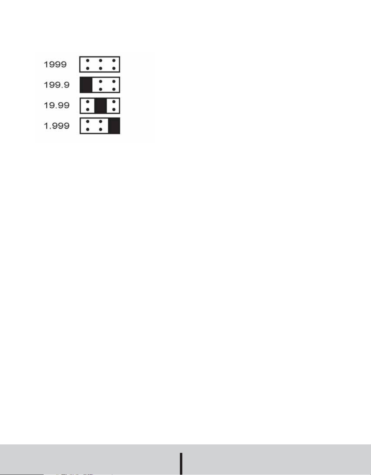
Selecting Decimal Point Position
Four decimal point positions are available on the digital panel
meter. Move the jumper to correspond to the desired decimal
point location. See Figure 2.
Figure 2
MAINTENANCE
Upon final installation of the Series DPMA-5 Digital Panel Meters,
no routine maintenance is required. A periodic check of the system
calibration is recommended. The Series DPMA-5 is not field
serviceable and should be returned if repair is needed (field repair
should not be attempted and may void warranty). Be sure to
include a brief description of the problem plus any relevant
application notes. Contact customer service to receive a return
good authorization number before shipping.
©Copyright 2008 Dwyer Instruments, Inc. Printed in U.S.A. 3/08 FR#R5-443474-10 Rev.1
DWYER INSTRUMENTS, INC.
Phone: 219/879-8000 www.dwyer-inst.com
P.O. BOX 373 • MICHIGAN CITY, INDIANA 46361, U.S.A. Fax: 219/872-9057 e-mail: info@dwyer-inst.com
 Loading...